


|
Would any goons be interested in a very small variable power supply? Might as well make "first" electronics projects useful right? I need to get permission to put the kits together first. However I'm putting feelers out, would any of you buy kits like that? PCB and all parts included? What would you pay?
|
 #
¿
Jan 21, 2008 16:01
#
¿
Jan 21, 2008 16:01
|
|


|

|
| # ¿ Apr 27, 2024 03:56 |
|
|
The Radiskull posted:I�ve found a video on youtube by some guys that do MAKE magazine. (I've never heard of it) but they managed use a laser printer and an iron to make the tracks for copper clad pcb! They Ironed the Toner onto the clad. As for the power supply thing, would you pay $7 for one? I was just pricing out the parts on digikey, and I could reasonably sell "kits" for about that.
|
|
#
¿
Jan 22, 2008 14:41
|
|
|
Skycks posted:I'd probably buy one, what kind of specs are we talking? Amp and a half, linear, up to 35v input. you'll need to maintain something like a 2v over your output for it to work though. Nothing crazy. But a quick eight or ten components to get someone soldering, and soldering something useful.
|
|
#
¿
Jan 22, 2008 19:07
|
|
|
That may be a situation where a boost power supply would be a good plan.
|
|
#
¿
Feb 8, 2008 15:27
|
|
|
So, tonight I actually got some silicon hooked up on my bicycle headlight project. I'm using a 7805 vreg to cut down the power from a 9.6v 2.3ah battery pack. I'm looking to drive 50leds at 20ma each. That butts right up against the limit of the 7805. I'm using groups of 10leds and 10ohms of resistors. I'm getting exactly the right voltage drop across the LED's. (that's 3.2v) So I think I've got that part right. Tonight I hooked up the 7805 and 20 leds. The 7805 got quite warm. I do not yet have a heatsink on it. That's something I can address easily... it's something I'd like to NOT address, if you get my drift. Which brings us to my question. I've never built a SMPS. I'd like to build one. Every switch mode power supply I've looked at seems to have a whole bunch of components. And I get somewhat lost while searching digikey for the proper one. Can any of you give me recommendations on a chip to go with? I was hoping to find something in a 5 pin to-220 package. And what I should do for the inductor?
|
|
#
¿
Apr 1, 2008 10:00
|
|
|
While I don't have any lights on it, my bike helmet is red. :-) And I have a obnoxious red flashing taillight. My goal is to have enough light that I can ride confidently in the dark. I have a PCB layout that will net a very neat looking headlight. I have a road bike, and nothing is uglier than a bunch of stuff hanging off the bars. My bars are about 7/8" thick, and two rows of LED's are only about half an inch wide. I'm looking to have the headlight be a "stick" of light. Digging around on digikey, I found two good candidates. And I think I settled on the LM2576. http://www.national.com/ds/LM/LM2576.pdf It has a wider acceptable input voltage than the LM1575. The whole reference design is the chip, the inductor, a diode to handle the back emf from the inductor, and two caps. I think that's about as simple as it can get. Better than that, someone on ebay is selling sets of 10 of the needed components for $23. Having a stockpile of 5v 3A SMPS wouldn't be a bad thing.
|
|
#
¿
Apr 1, 2008 11:13
|
|
|
I'll have greater than 7v input at all times. Unless I want to destroy my nimh pack. I think that means I'm safe.
|
|
#
¿
Apr 1, 2008 22:50
|
|
|
The kind I have are 1amp. I was aware of the need to heatsink ;-) Just not that acutely aware. I apreciate the research you did. I've done biasing on linear vregs to adjust the output voltage before. However this will be a battery powered application, so I'd like to avoid the whole linear thing. I like the ziener idea. I need to check to see what the failure mode of the smps is. If it fails safe, I won't bother. if it fails on, poof, there goes $5 in white leds.
|
|
#
¿
Apr 2, 2008 00:44
|
|
|
UserNotFound posted:But a bicycle is the perfect place for a heatsink: lots of air movement! quote:Also, maybe I didn't read your orignal post well enough, but you could put 2 LEDs in series for a 6.4V drop, which would halve the power wasted by the resistors and be closer in efficiency to a switching supply? quote:Actually, what you should look into is to is use a 555 timer to blink the lights very quickly. 99% of LED lights do this to save power. That said, I do have a 556 in my parts box....
|
|
#
¿
Apr 2, 2008 16:16
|
|
|
Mach Won posted:Are you looking to drive the LED's with the 555? I know they can source up to 200mA, so it seems like that would not be enough. There's no way I'd try to source all the current through a 555. However a 555 has plenty of power to drive a FET. Which would be used to switch the LEDs. Not that I'm going to go that path.
|
|
#
¿
Apr 2, 2008 20:14
|
|
|
Hillridge posted:Rather than trying to put together a switcher, have you thought about just buying a power module? Something like this:*snip* That's a neat little power supply. But it won't handle more than a 5v input. So I'd still need something to step the voltage down to 5v. And they're $11.50 each. Check out the part I linked to earlier. The LM2576 is a neat little chip. I bought sets to build 10 of them, for $23.50 shipped. I just need to add two caps. For a total component count of five.
|
|
#
¿
Apr 2, 2008 22:12
|
|
|
Yaknow, the SMPS that I'm using for my headlight would be ideal for driving the PIC project as well.
|
|
#
¿
Apr 4, 2008 15:35
|
|
|
Captain Cool posted:First off, fifty LEDs will get you seen, but they won't illuminate the road in front of you. If you need to light up the road, you should look into high power LEDs, like 1-3W. The 7805's have been ditched. Read up a few posts to see what i found to deal with that particular bit of nastiness. Yes, nimh has a favorable discharge curve, but from fully charged, to discharged I'm looking at a drop of nearly 2.6v. I know LED's don't care about voltage, however I did do the math on the resistors, and it ended up being really ugly. That leads to my first, and second solutions. My first idea was to stack a few LEDs to get a big-ish voltage drop, and use small resistors. So say we put two LEDs in series, that gives us a 6.4v drop. The resistor to pass 20ma of current at 10.4v would be 200ohm. At 8.4v, it would be 100ohm. So I passed on that idea. Idea number two was to use big value resistors on single LED's. Which, if I understand the 7805 properly, is effectively the same thing without active voltage regulation. I'd be looking at a 7v drop, at 20ma, per led. I'd be burning up 7 watts of power doing that. So.. SMPS it is, with smallish value resistors. With the 100ohm resistors i'm dropping 1.6-1.8 volts across the resistor, so I only need to deal with a total of 1.8w of heat. I'm using pairs of half watt resistors, so I am sitting pretty in that respect. Unless I'm completely wrong....
|
|
#
¿
Apr 4, 2008 17:09
|
|
|
Mach Won posted:You guys doing this bike stuff need to figure out how to power your LED's off of your pedaling. Then these would be cool projects. Been there done that. They sell some very high efficiency hub generators that produce a few watts. Strangely enough, the drag from those generators does significantly impact your riding speed.
|
|
#
¿
Apr 4, 2008 18:52
|
|
|
Captain Cool posted:Hm. How well do 50 20-ma LEDs work compared to one 2W LED? It seems like spreading out the power would be much worse than having fewer, brighter lights, but I don't know. quote:Okay. I would be tempted to just plan for 9.6V and run the LEDs out of spec for the first 10 minutes or whatever. Or pick LEDs with enough overhead to handle the extra power. quote:You could run a comparator against a voltage reference and use a relay or power mosfet to switch from fresh-battery mode to normal-battery mode when the voltage drops to 9.8v or something.
|
|
#
¿
Apr 5, 2008 03:01
|
|
|
Frist off, good job Neko. As for my little power supply project; It works. I got the parts in the mail yesterday. So tonight I scrounged up reasonable value caps and soldered wires to all the parts. (I mistakenly got all SMT parts..) Hooked it up. And viola, it worked. ... though when I first set it up i was a little mystified why it wasn't working. Turns out I didn't hook up the input wire to the controller chip. Ooops. Pictures to follow. I took them.. just can't be bothered to get them off the camera or downsized, or uploaded, at the moment. However, the resistors i'm using for current limiting get a little warm. Maybe I should get the voltage adjustable version of this controller chip, and use some tiny value resistor on the LEDs Nerobro fucked around with this message at 06:38 on Apr 6, 2008 |
|
#
¿
Apr 6, 2008 06:35
|
|
|
So... What showed up was this. A great big pile of surface mount parts. Now.. how do you make those parts fit into a breadboard? You add wires of course! Strangely enough, It worked. And yes, it really is THAT bright.  Lights out.  So, next comes building PCBs.
|
|
#
¿
Apr 7, 2008 06:36
|
|
|
yes, there is a demand for that. Please do it.
|
|
#
¿
Apr 11, 2008 17:34
|
|
|
So, here's where I'm at. I have a 5v SMPS. I want to use it as a current source for my LED headlight. I understand you can use voltage regulators as current sources by fooling the sense pin. Using a shunt resistor is what comes to my mind immediately. SO, to get a 5v response back to the SMPS I have, I'd need to drop at least 5 volts across the shunt resistor. While the math for that is easy, finding a resistor that can handle 7w isn't. And I'm not so fond of the idea of burning off my power like that. My next genius thought was to find a regulator that had a lower input voltage. it seems the lowest common input voltage is 1.2-1.25v. And while that's a whole lot better than 5, that would still mean disapating more than a watt from the shunt resistor. What I think my solution is, is to use an op-amp to amplify the voltage from a shunt resistor. Say, a .05 or .005 ohm high precision resistor. Is this a good plan? Am I completely out of my gourd for thinking about this? Or should I just spend the $6-8 each for the 1-3-5w led drivers off of ebay. *goes off to re-read the op-amp tutorial*
|
|
#
¿
Apr 24, 2008 20:54
|
|
|
This is the most confusing thing about electronics. There's often JUST THE RIGHT part for a given application. But hell if I know what it is, what it's called, or even necessarily what to look for. I just looked up that part. That's... just plain awesome. It's also $2.50 a chip. Which isn't so bad. ;-) it's cheaper than buying completely new PSU parts. The whole point of this is so I don't end up burning off 2-3Wh through resistors.
|
|
#
¿
Apr 25, 2008 14:33
|
|
|
a 9.6v NiMH pack. :-) so that should work nicely.
|
|
#
¿
Apr 25, 2008 19:04
|
|
|
Yeah.. my SMPS is pretty much sealed. Otherwise I'd be looking at other ways of screwing with it. I'll go digging at digikey, see what else i can come up with. I just put in an order with TI for samples of that chip.
|
|
#
¿
Apr 27, 2008 06:00
|
|
|
YOU jerk. I just spent the last three days trying to figure this all out on my own. I just bought an opamp and dug up the circuts so I could mulitply the output of my shunt resistor to make my SMPS behave as a current supply. :-) Thanks, great writeup.
|
|
#
¿
May 1, 2008 00:06
|
|
|
mtwieg posted:I should also mention I program in straight assembly (I said it would be technical) ASM seems the most sane way to program PICs. :-) I can actually read it... I'd love the transistor writeup. If you can find the time.
|
|
#
¿
Sep 9, 2008 15:51
|
|
|
Or I could host it. If you e-mail it to nerobro at gmail dot com, I'll put it up on my webspace for ya.
|
|
#
¿
Dec 15, 2008 21:14
|
|
|
The construction of BJT's and FET's are wildly different. BJT's are just two diodes back to back. They're input (the gate?) is low impedence, and low capacitance. This means when you shut off the power to the gate, the transistor turns off very, very quickly. Their base-collector resistance is fairly high. The control current bleeds out through the collector. FET's input are high impedance, and high capacitance. It takes very little electricity to turn a FET on. And keep it on. This also means it takes a FET some time to bleed off power in the gate. The power applied to the gate, doesn't actually bleed off through the rest of the device. That's why it's a "field effect" transistor. FET's also have very low resistance, and I think very low voltage drop across the base and collector. (I am no expert, and I get confused often...)
|
|
#
¿
Feb 14, 2009 06:00
|
|
|
well there I go. Soldering again. A friend on freenode told me I needed to buy this: http://www.seeedstudio.com/depot/digital-storage-oscilloscope-with-panels-p-167.html It's a aurdino based 1mhz Digital Ociliscope. It arrived in the mail two days ago.  I looked at what's in the package, and i'm kinda intimidated. There's a whole heck of a lot of SMT parts. And some very very small components. I need an o-scope. I couldn't resist. As a warmup, I ordered this capacitor meter kit. http://www.seeedstudio.com/depot/capacitance-meter-kit-p-268.html And tonight, after working a 12 hour shift, I sat down and soldered it. The best part is, it works. It took me roughly 90 minutes. I'm quite happy I managed to complete it first try. Here's the result of that labor:  Assembled using this:  I haven't really done a whole lot of soldering since my friend and I were doing the paintball gun boards. So heres' the kit I got. http://www.seeedstudio.com/depot/digital-storage-oscilloscope-diy-kit-65288with-panels-p-166.html I'm just so excited that it worked. And gave a valid result when I tested it against the stockpile of components I've built up. Speaking of components, a different friend got a bag of crap from www.woot.com at christmas. In the box, was a crapton of electronics. I just started sorting the bits and peices. There's lots of 1/2 watt resistors. A few large diodes. Maybe two transistors. a $3 relay. And I'm still sorting the rest.  This all does eventually tie into my spring project. Which is a voltage doubler and regulator for 6v electrical systems. What do you guys know of charge pumps? Alternatively i'm going to go with a small 2:1 transformer to get the voltage high enough for a SMPS or even linear regs to handle it. Nerobro fucked around with this message at 10:16 on Mar 5, 2009 |
|
#
¿
Mar 5, 2009 09:53
|
|
|
clredwolf posted:That oscope looks sweet, I want one of those kits. I can't tell what size those components are though, wish they had a bigger picture. quote:If you want to solder SMDs, buy a good pair of tweezers. *SMT tips* quote:What are you doing with charge pumps btw? I'm interested in learning some more about those...
|
|
#
¿
Mar 6, 2009 11:28
|
|
|
Because it goes with that little buck-boost supply. Here's the joule theif http://www.emanator.demon.co.uk/bigclive/joule.htm
|
|
#
¿
Mar 7, 2009 04:33
|
|
|
Uh. Yeah. This is rather tricky. I wish i had some solder paste and a hot air pencil. I probally have it about half done. Do yourself a favor. Pay the $16 to get the assembled version. My time is worth more than $14 an hour, and I've put 90 mins in it so far.
|
|
#
¿
Mar 14, 2009 08:09
|
|
|
http://www.adafruit.com/ that's her website.
|
|
#
¿
Mar 22, 2009 07:31
|
|
|
An audiophile company could fund ALL of our stuff. ;-) Who wants to make the website. I'm handy with cable ends... On a "I'm a teacher" note. Yeah.... me teaching. Laugh. I had my roomie build his first vreg circuit. And then use that to feed a 555 timer to flash a LED. He then did some experimenting. He found out that LED's have different voltage drops when he put a red LED with his white LED's and only the red LED lit. Now here's the fun part. While I was out yesterday, he figured out that putting a resistor on the red led would bring it's voltage drop up to match the white leds. I'm kinda proud of him.
|
|
#
¿
Mar 22, 2009 21:32
|
|
|
More bragging.  That's the circuit my student came up with. And the chip that's just sitting there, well that's my fault. I hooked up the power leads backwards once, and let the smoke out of that 555.
|
|
#
¿
Mar 23, 2009 08:52
|
|
|
And.... what's the story :-) and who's going to host the site so we can start raking in cash? I'll buy the domain.
|
|
#
¿
Mar 23, 2009 20:55
|
|
|
I wholeheartedly agree with this route. Get at least a JDM2 compatible programmer. The life you save will be your own. The relationships you save will be your whole family.
|
|
#
¿
Mar 24, 2009 03:16
|
|
|
Yeah, it'll work.
|
|
#
¿
Apr 29, 2009 20:33
|
|
|
I got a new toy yesterday. A DSO Nano. I'm pretty pleased with it so far. That said, I'm a noob, and the concept of "graphing voltmeter" still gets my manbits tingly. What I have found so far, is that it can handle up to 60v input, and down to 500mv. It has a 1mhz sample rate, with a 12 bit DAC. It has a built in test signal, that can be varied from 500-2000hz, and 50-99% duty cycle. It has an adjustable trigger, and how ti triggers can be chagned. It has adjustable display offset. Uh.... I"m still exploring.
|
|
#
¿
Aug 21, 2011 05:11
|
|
|
I bought one of those DIY scopes too. I blew up a couple of the caps building it, so it didn't ever work for me. I still have the kit. Perhaps I can scavenge the AVR and display.
|
|
#
¿
Aug 21, 2011 08:58
|
|
|
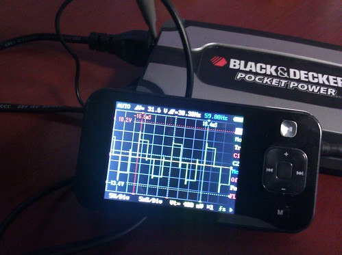 IMG_20110824_090812.jpg by nerobro, on Flickr Hey, look, it actually works. That's the output waveform from that inverter, with a very light AC load on it. That's ugly as hell, but it proves the DSO actually works.
|
|
#
¿
Aug 30, 2011 19:07
|
|
|

|
| # ¿ Apr 27, 2024 03:56 |
|
|
Pizer posted:What are you using to display the waveform? Looks handy. Clipped the ground lead to one side of the AC socket, and the sense lead to the other. And set the probe to 10x. No real magic there. The load was a battery charger.
|
|
#
¿
Aug 31, 2011 21:40
|
|