|
I've been wanting to start a thread like this for a while, and forums user Fucknag posted this awesome info in the News thread that sparked up a bunch of interest. We can use this thread to share a lot of really technical automotive engineering info because that poo poo is awesome. Personally I am a Mechanical Engineering senior. I'll get my degree in May. In the time that I've been studying, I've designed some products for Chase Bays, and I'm currently working on designing a set of Cayman S headers for Track One, making a custom ITB setup for my e30, and mocking up an engine in a CFD software to spec some custom cams and design the exhaust! Fun stuff! I'll fire it off with a video that has been posted in here before. This video is a fantastic explanation of how differentials work! Plus you get an old timey  voice over. voice over.https://www.youtube.com/watch?v=K4JhruinbWc
|
|
|
|

|
| # ? Apr 26, 2024 11:12 |
|
Also here's Forums user Fucknag's awesome effortpost that sparked off requests for the thread in the News thread!Fucknag posted:Crossplane vs Flatplane V8s: What the gently caress is actually going on? Fucknag posted:Twin scroll turbos: scavenging for boost
|
|
|
|
I'm going to try and make a post about the properties of compressible flow. Please correct me if you see anything wrong - I've still got a lot to learn about the subject! Compressible Flow is Weird as poo poo! For most of your education as an ME, you treat fluids as incompressible. This is the fluids equivalent of neglecting friction and air resistance in a basic physics equation. It's a reasonable approximation in some cases, but mostly it makes the problem a lot easier to understand and solve. Please note that compressed gas is also treated as a fluid. The best way to explain compressible vs. incompressible flows are to compare the properties of air and water! Ideally, your car sucks up air. ICEs are big air pumps, basically. Air is compressible, so when the piston moves up in the cylinder to compress the intake charge, nothing bad happens! If you're unfortunate or dumb enough to drive into a lake, you can end up sucking in a charge of water instead. Water is incompressible. When the piston tries to compress the water it sucked in, bad things happen. The water doesn't "move". It's like the piston hits a brick wall.  Ouch. Compressible flows make things a lot more complicated. You need to account for significant changes in volume and density. Some basic fluid dynamics stuff should be covered first.  This is Bernouli's equation. It relies on the first law of thermodynamics - energy cannot be created or destroyed, it can only change form. You'll notice something counter-intuitive is going on in this picture. When incompressible fluid flows from a larger diameter into a smaller one, pressure decreases. You'd expect pressure to increase when you're squeezing the flow into a smaller area, right? Nope! This is the change of form of energy at play. Mass flow is constant in this example - the same amount of mass of water is entering and leaving the pipe. When you decrease the diameter, you are decreasing the cross sectional area of the pipe. This means that for the same velocity or speed of the fluid, you'll be flowing less mass of water per second. This violates conservation of mass! In order to deliver the same mass flow rate, the flow has to speed up. Think about capping a hose off with your thumb. The water flows faster and farther, right? Now conservation of energy comes into play. The second term of Bernouli's equation has just increased - the flow has more kinect energy from its higher velocity. That energy has to come from somewhere. The energy stored in the pressure of the flow effective converts into kinect energy. Smaller diameter = faster flow, lower pressure. Remember this bit, it's important later. I'm going to come back later and fill in some more stuff! Next bit: ~The Speed of Sound~
|
|
|
|
I do design work for an industrial power tool manufacturer. I dont really have anything about that to share that I can think of right now. But have some cool engineering videos. https://www.youtube.com/watch?v=Y5pen3QMgzQ https://www.youtube.com/watch?v=KBMU6l6GsdM https://www.youtube.com/watch?v=YwI48O0MUXY https://www.youtube.com/watch?v=A3X8cuJKyns And lastly, what im watching tonight. Ive probably watched this 4 or 5 times end to end since I found it a few years ago. https://www.youtube.com/watch?v=W2VygftZSCs
|
|
|
|
There are many things you can learn from this website: http://www.autozine.org/technical_school/tech_index.html
|
|
|
|
That shuttle video is one of the most amazing things I've ever seen. The way that nozzle was flexing on startup!
|
|
|
|
Love this video. I mean, slow-motion rockets, come on. Can't believe I inspired this thread to be posted, but I guess I'll accept all this praise heaped upon me; I am but a lowly engineering student at a community college, I just learn about this stuff for fun. v I'll try an do some more writeups later, particularly that one on vibrations that I promised. In the meantime, have this https://www.youtube.com/watch?v=s1i-dnAH9Y4
|
|
|
|
Professionally, I'm a high performance computing systems engineer with ten years experience, I used to plan SANs and high performance server arrays for companies, mostly for high performance databasing systems.  Now, I just do systems administration for a small company while attending school for Nuclear Physics. I'll see if I can dig up some of my layouts and proposals I've done for companies in the past. CommieGIR fucked around with this message at 05:09 on Nov 20, 2014 |
|
|
|
I play KSP on a 6 year old laptop, so I'm pretty familiar with slow motion rockets actually  (seriously though that video had me drooling all over the drat place, so cool)
|
|
|
|
Fucknag posted:
This right here is amazing. I never thought about how mechanical computers worked before, but the basics really are very simple and it all makes a very obvious kind of sense once you see it in action. It's a pity math isn't taught this way. I never would have thought of a differential as a tool for addition.
|
|
|
|
If we're going to get technical I have a bone to pick with some of the laypeople on car forums. By the way, I never, ever use my credentials in a technical discussion because 1) it's a logical fallacy (argument from authority) and 2) if you can't explain it without saying "just trust me I'm an engineer" then you need to improve your communication skills. That said, I too am a mechanical engineer, with a degree and 26 years of industry experience. Hopefully most of you are hearing that for the first or maybe 2nd time. You will never hear it from me in the context of a debate. But back to the bone: Lately I have seen the phrase "Oh my god they mounted it in SINGLE SHEAR?" come up on a variety of forums and discussions. It's like people had an engineering-word-of-the-day calendar and glommed on to that phrase like it was committing a cardinal sin. Here's the thing. Single shear is just another way of mounting things. If something is under-designed it's going to fail because it's under-designed, not because of how it's configured. Here are just a few things that are installed in single shear on many cars: all 4 wheels. Most ball joints. Steering wheel. Alternator pulley. Crank pulley. Transmission output shaft. Door hinges. And on many cars, shocks are mounted in single shear. It's just that they are designed right, so they never cause a problem. I remember when someone in here bought a Lotus Elise and had a toe link failure that was apparently common on cars pushed hard. It was a standard ball joint connection like on many steering and toe links in the industry, but someone in the thread piped up with the whole OH MY GOD SINGLE SHEAR HOW COULD LOTUS DO THAT statement as if it is forbidden. Stop it. You did not just discover the big weak link like it was some fundamental truth that all engineers should stick to. It was just under-designed, and the engineers did not predict the kind of use that led to its failure, and therefore didn't test thoroughly enough. Another common one is comments on that giant SEMA 4x4 that breaks its suspension over a jump. Yes they mounted massive coilovers on a very heavy truck in single shear, but given that they were homebrewing the entire suspension by gut feel, the odds are that those mounts would have failed in double shear too. The entire weight of the truck was SHOCK LOADING the bolts and there was clearly zero engineering done on the sizing. If those were massive bolts, the single shear mounting would have worked just fine. So come on guys: don't try to make yourself sound smart by pointing out that something failed in single shear. Failures happen due to under-designing things regardless of configuration.
|
|
|
|
/\/\/\/\/\ You can gently caress right off with that logical science talk. https://www.youtube.com/watch?v=rLDgQg6bq7o
|
|
|
|
LloydDobler posted:By the way, I never, ever use my credentials in a technical discussion I wanted to list mine so you know I'm some schmuck who isn't out of school yet. I've still got a lot to learn and I hope people as experienced as you will chime in when I say something totally loving wrong. It helps me learn  Speaking of, here's some more things I hope aren't terribly wrong! ~The Speed of Sound~ I'm sure most of you are familiar with things like the Doppler Effect and the speed of sound and the big BOOM jets make when the break the sound barrier.  So, here we have a missle flying at Mach 0.5, Mach 1.0, and Mach 1.5. The Mach number is a ratio of velocity to speed of sound. At Mach 1.0, velocity is equal to the speed of sound. Anyway, sound consists of pressure waves. These waves move at the speed of sound. You see in the Mach 0.5 case, as the missle moves it emits sound waves. Because it is moving so quickly, these waves are asymmetric. Towards the front of the missle, the waves are closer together. This gives the sound it is emitting a higher frequency! That's where the Doppler Effect comes in. Here's the neat thing - when a craft reaches Mach 1.0, it is traveling at the exact same speed as the sound waves it is emitting! This is why you here a loud BOOM when something moves through the sound barrier - what you're hearing is a bunch of sound waves hitting you at the same time! Once something breaks the sound barrier, it outruns the sound it is producing. That's why if a fighter approaches you at speeds above Mach 1.0, you don't hear anything until it is already past you  High Mach number flow has a lot of weird things that happen. Remember that relationship between cross sectional area, velocity, and pressure I mentioned last time? Supersonic flow flips that on its head - expanding to a larger area increases velocity and decreases pressure. I do have a question for yall, as I've had a hard time searching for this. Searching keeps bringing up ramjets and turbine engines. I'm pretty sure when an exhaust valve first opens, you would end up with a choked condition at the valve. Is there a way to manipulate this and turn the flow supersonic? Or are the conditions too unstable and short lived to make it worthwhile? The reason I ask is when I saw megaphones being used in exhaust manifolds, I figured the collector necked down to reached choked flow conditions, and the megaphone was used to expand the flow and push it into the supersonic range. Party Alarm fucked around with this message at 01:08 on Nov 21, 2014 |
|
|
|
Party Alarm posted:I'm pretty sure when an exhaust valve first opens, you would end up with a choked condition at the valve. Is there a way to manipulate this and turn the flow supersonic? Or are the conditions too unstable and short lived to make it worthwhile? Something like this? https://www.youtube.com/watch?v=YYNCGZCul1Q (diagram at about the 0:40 mark) They use a neck to get supersonic speeds, and the guy likens it to a rocket engine's nozzle. rarbatrol fucked around with this message at 02:32 on Nov 21, 2014 |
|
|
|
Sadi posted:And lastly, what im watching tonight. Ive probably watched this 4 or 5 times end to end since I found it a few years ago. Worth noting to anyone who missed it: there's a link to a (legal - the footage is all public domain, being government sourced) downloadable DVD ISO in the video info - download, burn. and play it on a big screen with a good sound system. Just playing the video on a little monitor and computer speakers doesn't do it justice.
|
|
|
|
Party Alarm posted:I wanted to list mine so you know I'm some schmuck who isn't out of school yet. I've still got a lot to learn and I hope people as experienced as you will chime in when I say something totally loving wrong. It helps me learn Oh yeah I wasn't calling you out or anything, it was more of a disclaimer as to why I was posting mine. I had a great burn on a guy whose opinions were being challenged on a car forum, to which his response was "I'm too well paid as an engineer to argue about engineering on the internet in my spare time" and talked about how many languages he spoke so he could travel the world on his job, then in the same paragraph announced that he's never been one to brag. I asked if one of his languages was irony and he called me an rear end in a top hat and quit the entire forum in a huff. Fun with engineers on the web. Also I have absolutely no comprehension of shockwaves and stuff like that. I'd have been one of the guys in the 60's who was all "you can't go faster than sound, you'll probably die!"
|
|
|
|
It gets weird fast. I found some good information on the subject in the past few hours but it's going to take some time to digest and process. I'll share what I can when I can! 
|
|
|
|
1) Here's my go to source for how AWD works. 2) How does AWD work?
|
|
|
|
Throatwarbler posted:1) Here's my go to source for how AWD works. https://www.youtube.com/watch?v=MjaCbpw84kw https://www.youtube.com/watch?v=UL9LmT3fzbQ
|
|
|
|
Awesome thread so far. Is there any concise write-up or video that really brakes down how a transmission works? This is one of the things I'm really clueless about, how the 2 shafts engage one another, how the syncros work, how the shifter fork controls the gear selection, etc. Something that steps through the entire shifting process would clarify quite a lot for me.
|
|
|
|
It doesn't look like a modern transmission and the first part is dumbed down, but the power flow works the same and I'm a total sucker for pre-WWII technical videos so here's this: https://www.youtube.com/watch?v=aAWxZRuBXtw e: also this one is the one I should link, since it's the one most schools use: https://www.youtube.com/watch?v=IKywZ730JFs Turbo Fondant fucked around with this message at 08:03 on Nov 29, 2014 |
|
|
|
Speaking of AWD, here is how it works in a subaru 5-speed manual transmission: From the motor, power goes through the clutch to the the main shaft, which has all the drive gears. The drive gears are meshed with the driven gears, which are on the driven shaft, which is hollow. Here is the transmission: 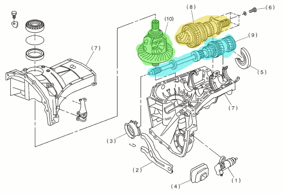 The main shaft, which is connected to the clutch, is blue. The driven shaft is yellow and the front diff is green. Here is the driven shaft: 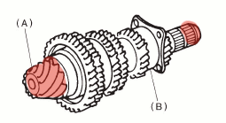 The part highlighted in red is the drive pinion. It is inside the driven shaft. Here is an exploded view: 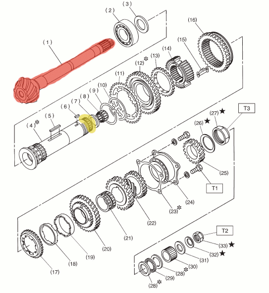 Once again the red part is the drive pinion. The little part highlighted in yellow is where the driven shaft connects to the center differential. All those other things are the driven gears, dogs, collars, and syncros, etc. Here is the center differential: 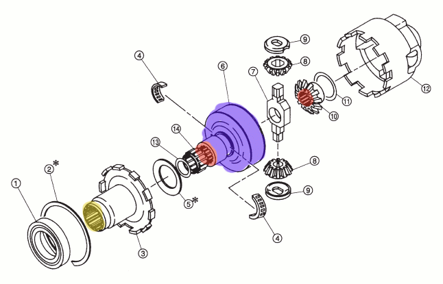 The red is where the drive pinion connect to the differential. The yellow is where the driven shaft connects to the center differential. The viscous coupling is purple. If there is a speed difference it starts to lock up. The red part labeled "10" connects to the rear transfer drive gear. Here is the transfer case: 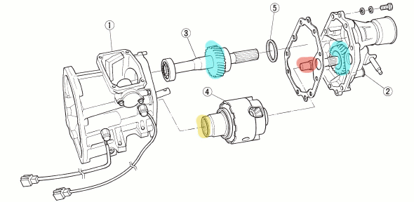 Yellow, once again, is where the driven shaft connects. Blue are the transfer gears to send power to the rear. Red is where the transfer driven shaft connects to the center differential (item 10 in the previous picture). How does this all work? Power goes from the clutch to the main shaft, through the selected gear to the driven shaft which turns the center diff. From there it is split to the front diff and through the transfer gear to the rear diff. When there is a speed difference between the front and rear, the viscous coupling heats up and tries to speed up the slower moving end. Now, the viscous coupling is not supposed to be able to transfer all of the power to one end. The stock unit is rated at 4 kg-m/100rpm. What that means is that for a 100 rpm speed difference in the coupling, it will provide 4 kg-m, or about 28 lb-ft, of resistance. However, this relationship is not linear (one of the downsides to a vc), and there is a limit to how much power can actually be transferred. 200 rpm difference does not mean 56 lb-ft is transferred. How much the vc can actually lock up, I'm not sure. For all I know it's proprietary information that Subaru doesn't release. What I can say is that it is much less than the full power of a car. I read someone jacked up the rear of a WRX, put a 2x4 on the ground in front of the front wheels, and put the car in gear. The car was unable to pull itself over the wood by the front wheels and the rears just sat there spinning in the air, even after revving it to over 4k rpm. Subaru does, however, make stronger center viscous couplings, in 10, 12, and 20 kg-m/100rpm varieties. Everything I have heard about the 20 is that you should not use it driving around on the street, and that it will bind up and cause hopping etc as if the 4wd was engaged in a truck. Seems to be good in rally cars, though. Also here are some other things I've written and links I've collected: http://hellafunctional.com/?page_id=660 haven't updated that page in awhile, but this one about coolant is pretty good: http://hellafunctional.com/?p=629 jamal fucked around with this message at 08:12 on Nov 29, 2014 |
|
|
|
jamal posted:
Here's the Audi Quattro gearbox and transfer case for comparison  I don't have as cool a breakdown as Jamal 
CommieGIR fucked around with this message at 13:56 on Nov 29, 2014 |
|
|
|
How do stuff like brake boosters and all the other vacuum-powered doodads (HVAC controls on older cars, for one) on a regular engine work on a supercharged/turbo'd engine presumably always running at positive manifold pressure? Separate air pump? Tangentially, maybe more appropriate for the aeronautical thread, but I figured I'd post it here because it's technical: I've read that old piston aero engines (i.e., the big radials and I'd assume the inline fighter engines too) set the power with manifold pressure rather than throttle. What does that mean? Did I just misread, and they moved the throttle and used the boost gauge to read the result?
|
|
|
|
Delivery McGee posted:How do stuff like brake boosters and all the other vacuum-powered doodads (HVAC controls on older cars, for one) on a regular engine work on a supercharged/turbo'd engine presumably always running at positive manifold pressure? Separate air pump? It varies, on most boosted cars there is still a vacuum present at the throttle plate so you can still feasibly get vaccuum there. On many Audi/Porsche builds, they had a mechanically cam driven vacuum pump or an electric vacuum pump.
|
|
|
|
CommieGIR posted:It varies, on most boosted cars there is still a vacuum present at the throttle plate so you can still feasibly get vaccuum there. On many Audi/Porsche builds, they had a mechanically cam driven vacuum pump or an electric vacuum pump. Additionally, vacuum brake boosters all have a check valve so if the engine stalls or goes WOT you still have 1-2 stops' worth of vacuum in the booster. On a boosted engine it will also keep the boost out. Also you generally won't be into much boost and on the brake pedal for more than the very short period it takes for the boost to dissipate once you're off the throttle (unless you're doing a brake stand burnout). And they tend to avoid other vacuum-driven accessories on boosted cars in general (cable heater controls are better anyway IMO), but I know a few cars have vacuum reservoirs with check valves in the same vein. Turbo Fondant fucked around with this message at 17:02 on Nov 29, 2014 |
|
|
|
Delivery McGee posted:Tangentially, maybe more appropriate for the aeronautical thread, but I figured I'd post it here because it's technical: In all but the most modern automotive gas engines, the accelerator pedal actually controls the manifold pressure of the engine...you just don't notice it (or need to know it for that matter). Recall that the engine is constantly pumping air, with the throttle plate acting as a restriction. With a low power setting, the throttle plate severely restricts airflow into the intake manifold, creating manifold vacuum. At higher power settings, the throttle plate opens, which progressively reduces the restriction, increasing manifold pressure until wide-open throttle where manifold pressure is effectively that of the ambient air. Obviously with forced induction, there is a point where the manifold pressure begins to exceed ambient and anything beyond that is boost. Aircraft engines use manifold pressure for setting power because with a constant-speed propeller (all but the most rudimentary of trainers use constant-speed props), the engine speed will remain constant for virtually any combination of aircraft speed and throttle position.
|
|
|
|
Fun fact: Some forced induction aircraft engines, notably the Wright R-1820 as installed in late-model B-17s, after climbing through a certain altitude, you would firewall the throttles, open the intake ram air doors (bypasses the intake air filter, and uses the slipstream to make a bit of positive pressure,) tighten down the friction locks, and then use the waste-gate control levers to set engine power. As described above, aircraft engine RPM with a constant speed prop is set by the propellor, so engine power for a given RPM is set by manifold pressure. In every piston engine I've ever seen, that power setting is described in inches of manifold pressure (which is graduated in inches of mercury,) making no differentiation between manifold vacuum and boost. Aircraft also have a class of forced induction that I don't believe I've seen much of in the automotive world: turbo-normalization. Instead of using a turbo to make boost, you simply use it to keep the intake air at sea-level pressure. They're popular as modifications, since you can greatly increase climb rates and service ceiling in low performance aircraft, without the expense and of a true positive-manifold pressure turbocharged engine. Regardless of natural aspiration or forced induction, the operating handbook will have a table of power settings, IE: to get 80% power, you set 2400rpm, and 24" manifold pressure. The actual throttle handle position will vary with altitude. Keeping the same power setting during a significant altitude change can be a pain in the rear end. Most aircraft engines still use cutting-edge-1930s technology for engine management.
|
|
|
|
MrYenko posted:Fun fact: Some forced induction aircraft engines, notably the Wright R-1820 as installed in late-model B-17s, after climbing through a certain altitude, you would firewall the throttles, open the intake ram air doors (bypasses the intake air filter, and uses the slipstream to make a bit of positive pressure,) tighten down the friction locks, and then use the waste-gate control levers to set engine power. The B-17 had a unique little turbo supercharger to help keep intake air at sea level pressures at high altitude: https://www.youtube.com/watch?v=TpavBm5BHX8 
|
|
|
|
MrYenko posted:As described above, aircraft engine RPM with a constant speed prop is set by the propellor, so engine power for a given RPM is set by manifold pressure. In every piston engine I've ever seen, that power setting is described in inches of manifold pressure (which is graduated in inches of mercury,) making no differentiation between manifold vacuum and boost. Like most things in aviation, the Brits were different. In most of their fighters, manifold pressure was reported in pounds per square inch, with vacuum being negative numbers and boost being positive numbers, more like the boost gauges we see in cars (as opposed to the absolute manifold pressure gauges we see in most non-British aircraft).
|
|
|
|
What I want to know is, how do automatic transmissions decide when to shift, and I don't mean the usual "here is a torque converter and then magic happens and your gears shift by themselves". What I mean is, how does your transmission decide when to shift.
|
|
|
|
Wild EEPROM posted:What I want to know is, how do automatic transmissions decide when to shift, and I don't mean the usual "here is a torque converter and then magic happens and your gears shift by themselves". http://auto.howstuffworks.com/automatic-transmission13.htm Basically: a Hydraulic analog computer, as fluid pressure increases, the transmission bands will change. Each shift requires a certain pressure range to be engaged or disengaged. Most modern cars have electric solenoids that smooth out the shift pattern and can manually induce the shift to occur: https://www.youtube.com/watch?v=HcNH9AFWaNI CommieGIR fucked around with this message at 23:48 on Nov 29, 2014 |
|
|
|
As a 3rd Mechanical Engineering student I am enjoying this thread. I'm not as good at Fluid Mechanics as Party Alarm, my school focuses more on material science. If anyone is interested I can talk about bearing materials, rotating assemblies and why balancing is important, lubrication and other material related topics. For some topics I can even post pictures because I am in the middle of a 400 SBC build and about to start a 302 SBF build for my father. I won't claim to know everything, but talking with machinists and doing these rebuilds has drastically changed my knowledge of engines and I'd love to share.
|
|
|
|
CommieGIR posted:http://auto.howstuffworks.com/automatic-transmission13.htm To add to this the shift points in a non electronic automatic are controlled by a governor and a throttle valve cable or a vacuum modulator. The Throttle Valve Cable is the input for the Analog Computer that is the Automatic trans valve body. http://www.tvmadeez.com/article/ Lengthy explanation of the inner workings of an A541E. This one's electronic, mind you: http://www.meisners.net/Camry/WebSite/Links/Motor%20Age%20Magazine%20Toyota%20Camry%20--%20Electronics.htm I'm no expert but I have a morbid fascination with automatic transmissions because I seem to have a particular skill for breaking them That and I had a Ford Taurus. The AX4S in it was the biggest piece of poo poo.
|
|
|
|
Vanagoon posted:To add to this the shift points in a non electronic automatic are controlled by a governor and a throttle valve cable or a vacuum modulator. Even modern transmissions still have a governor, mostly for controlling/regulating hydraulic pressure. But yeah, on 70/80s Mercedes (CSB can back me up here) the transmission upshift/downshift is vacuum controlled. Granted, if that goes out it will still shift so long as there is sufficient hydraulic pressure, but it will be jerky as hell.
|
|
|
|
yeah and you can modulate shift pressure by spinning the modulator. iirc one revolution is 10psi line pressure. There is also a "wot" switch that cranks line pressure to max via solenoid and will enable two downshifts depending on governors output. Think of it like a modern counterpart sport mode. Those old boxes also had a TV cable that regulated holding pressure for the clutches/bands. I hate automatics, but form a engineering standpoint I find them immensely fascinating and have rebuilt many The 722.5 (5 speed auto) was a sort of hybrid of auto/electronic control as it had a solenoid for the first 4 gears, it was pulsed iirc at 300hz. without it the trans would shift 1-3-5. 722.2/3/4 are fairly simple creatures in comparison. I'd equate them to a 4 speed version of a TH350/400. 4th is not OD, its 1:1. and theres no tcc.
|
|
|
|
I should post a link To Tim Hunkin's The Secret life of Machines. These are brilliant. At least one of them is relevant to the thread - The Internal Combustion Engine. http://www.exploratorium.edu/ronh/SLOM/index.html Tim Hunkin Rules.
|
|
|
|
CBD posted:As a 3rd Mechanical Engineering student I am enjoying this thread. I'd be interesting in hearing about those topics. They are certainly things my school managed to skip over. I've got basics about bearings and lubrication but it's mostly from supplier texts and tribal knowledge.
|
|
|
|
Vanagoon posted:I should post a link To Tim Hunkin's The Secret life of Machines. Secret Life of Machines was one of the big influences on my childhood. I have them all on my media drive, and rewatch them every few years. They should be part of the curriculum in middle/high school.
|
|
|
|

|
| # ? Apr 26, 2024 11:12 |
|
Sadi posted:And lastly, what im watching tonight. Ive probably watched this 4 or 5 times end to end since I found it a few years ago. They talked more about the cameras than the shuttle  Great video.
|
|
|





 Bad Angus! Bad!