


|
No trade secrets, it's beer. Right now I have it set up with the air nozzle always blowing, but have quality concerns about blowing air into the can. No other gas would be cheap enough to use for this, hence why I'm trying to set it up to only trigger for a specific can. If I can get that set up I could also just use CO2 since it would be running very infrequently and eliminate all quality concerns. I know what sensors I need to use and how I would set them up but for example don't know how to power them or get the signal from the two sensors to trigger the relay. I've googled around for this but can"t seem to find a good resource to teach me these things. Appreciate all the responses.
|
 #
?
May 21, 2020 18:09
#
?
May 21, 2020 18:09
|
|


|

|
| # ? Apr 16, 2024 19:17 |
|
|
The screen door blows open and the wind whispers "....aaaaaarrrduiiiiiiiinoooooo..."
|
|
#
?
May 21, 2020 18:11
|
|


|
Is this the kind of industrial thing where failing to do its job or being down for any amount of time for repair will cost millions of dollars or w/e because I'd think that will significantly change the answers
|
|
#
?
May 21, 2020 18:20
|
|


|
If this is the kind of industrial thing where failing to do its job or being down for any amount of time for repair will cost millions of dollars I think the poster should not be asking how to roll a system themselves on The Something Is Awful discussion forums. Certainly not if their questions start with "how do I power this sensor." Hire an engineer. q.v. that guy who wanted to build a 5000 watt LED array for a dance floor
|
|
#
?
May 21, 2020 18:23
|
|
|
I was thinking of blowing air over sealed cans. I can see how you wouldn't just want to crank whatever's floating around the room right into totally open beer cans. I really like density/weight-based solutions for this because they're robust to room lighting changes etc. But for your actual question I second Arduino. I think most of them give you 3.3V and 5V from a USB supply. I assume you don't need guaranteed PPM failure rates or anything because this is presumably a pilot project and qualification etc comes later, but no matter what you set up don't expect low error rates off the bat unless somebody sold the solution to you and guaranteed that in writing.
|
|
#
?
May 21, 2020 18:30
|
|

|
I asked about this in the wiring thread, but I'll ask here as well. How do I measure power consumption of a 220v appliance to get it's cost to run? I'm wanting to figure out exactly how much a heat pump water heater is saving me, so I have my old resistance water heater hooked up and valved so I can switch between it and the new heat pump unit. I can obviously clamp a CT over each leg, but I'm not sure if I should be adding those values or taking the highest value or what. I'm sure it's a complex load that's running 110v for some stuff and 220v for some other stuff. There's fans and compressors and electronics and resistive heaters all inside this thing.
|
|
#
?
May 21, 2020 19:27
|
|

|
I assume you're in the US so this is an appliance with a 4-prong L1/L2/N/G outlet. The total power is the sum of the currents in the 2 hot wires times 120V. There's probably not much flowing through the neutral so you could likely cheap out and measure one leg and multiply the current by 240 but the two leg method will work no matter what the load looks like.
|
|
#
?
May 21, 2020 19:44
|
|
|
For a water heater, the vast majority of the power consumption will be resistive and you don't really need anything more than Power = V_rms * I_rms So measure average current going in with your current transducer clamped over one lead, assume that the voltage is 220Vrms (or measure it very carefully), then multiply to get the power dissipated. This won't tell you how much of that power goes into the water, but that would require knowing a lot of efficiency information specific to the water heater design. Doing an actual cost comparison between the two will require stuff beyond straight electrical power usage and won't be a simple number. Imagine if you had two heaters where one had more efficient heating and one had better insulation. Cost comparison will give you different answers for which is better depending on how much you are heating up new cold water vs maintaining temp on previously heated water.
|
|
#
?
May 21, 2020 19:48
|
|

|
Stack Machine posted:I assume you're in the US so this is an appliance with a 4-prong L1/L2/N/G outlet. The total power is the sum of the currents in the 2 hot wires times 120V. There's probably not much flowing through the neutral so you could likely cheap out and measure one leg and multiply the current by 240 but the two leg method will work no matter what the load looks like. It's L1/L2/G. This is how every water heater I've seen around here (Missouri) is wired. Foxfire_ posted:For a water heater, the vast majority of the power consumption will be resistive and you don't really need anything more than Note that the new water heater is a heat pump water heater and depending on the mode its running in it will use no resistive heating. Foxfire_ posted:Doing an actual cost comparison between the two will require stuff beyond straight electrical power usage and won't be a simple number. Imagine if you had two heaters where one had more efficient heating and one had better insulation. Cost comparison will give you different answers for which is better depending on how much you are heating up new cold water vs maintaining temp on previously heated water. I'm looking at understanding the system as a whole. If I run one of them for a month and measure it's power consumption over that time and then do the same with the other...that should tell me how much it costs to run each of them no?
|
|
#
?
May 21, 2020 20:05
|
|
|
If you are sure the third wire is a ground and not a neutral and the appliance is functioning correctly there is guaranteed to be 0 current flowing in the ground, so the currents in the two hot legs will be equal and you can just use a single current transformer on either hot wire and multiply that by 240 (less accurate) or the measured voltage (more accurate) to get your power usage. Even if it were a thing with L1/L2/N, the 120V paths are almost always very lightly loaded, e.g. only used for powering control electronics.
|
|
#
?
May 21, 2020 20:19
|
|
|
Josh Wow posted:No trade secrets, it's beer. Right now I have it set up with the air nozzle always blowing, but have quality concerns about blowing air into the can. No other gas would be cheap enough to use for this, hence why I'm trying to set it up to only trigger for a specific can. If I can get that set up I could also just use CO2 since it would be running very infrequently and eliminate all quality concerns. CO2 probably isn't a great idea either unless you've got air monitoring sensors. Your $4 micro got hung up and just opened the air solenoid for two hours, now you've got no air to breathe. Serious answer: PLC and industrial controls/sensors. And also talk to your manufacturing engineer, this is what they get paid to build.
|
|
#
?
May 22, 2020 02:02
|
|


|
A CO2 displaced environment is definitely noticable and not pleasant to be in like a CO one. Your body actually has a triggered response to CO2 of the "OH GOD I CANT BREATHE" variety.
|
|
#
?
May 22, 2020 02:48
|
|

|
Some kind of mini PLC is probably what you want, lots of things about like the photo below that have varying levels of expandability and programmability and cost < $500 This particular one I just grabbed because its a good example of the form factor I know nothing about it 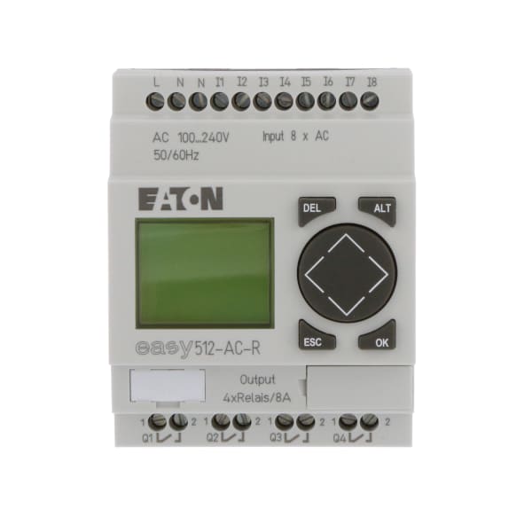 You could also do it with arduino (or similar) stuff but one of these will already be industrial and have features like IO that won't blow up when you breath on them wrong. Usually these come with graphical programming systems, which might be a plus. taqueso fucked around with this message at 03:39 on May 22, 2020 |
|
#
?
May 22, 2020 03:37
|
|


|
um excuse me posted:A CO2 displaced environment is definitely noticable and not pleasant to be in like a CO one. Your body actually has a triggered response to CO2 of the "OH GOD I CANT BREATHE" variety. Oh I know, but lack of oxygen takes no prisoners. Maybe it's hyperbole, but my point still stands. PLCs exist for a reason in industry.
|
|
#
?
May 22, 2020 03:41
|
|
|
I need a handful of tactile switches for some coronaprojecting, but it turns out shipping 20 switches costs as much as or more than the switches themselves (sad, but not really surprising). As I have to imagine I'm well below whatever minimum weight / volume would increase shipping costs, are there any miscellaneous components that would typically be useful to have on hand for future yet unknown projects, so I can actually get my money's worth out of the shipping costs? Alternatively, is there anywhere better than Digikey / Mouser for buying small numbers of very specifically sized components?
|
|
#
?
May 22, 2020 03:56
|
|


|
Voltage regulators are pretty useful to have on hand. Something like 10x LM317s? Get some heatsinks too if you think you'll drop the input voltage by a largish amount/get near its current limit.
|
|
#
?
May 22, 2020 04:16
|
|

|
For switches, instead of buying 20 + shipping from Digikey, it's often worth it to buy 1000 + express shipping from AliExpress
|
|
#
?
May 22, 2020 04:17
|
|

|
Use a Micrologix plc or similar. AutomationDirect have some interesting units that I have never usedante posted:For switches, instead of buying 20 + shipping from Digikey, it's often worth it to buy 1000 + express shipping from AliExpress Sure, as long as you have no expectation of lifespan or reliability (or fire safety) Piss Meridian fucked around with this message at 04:58 on May 22, 2020 |
|
#
?
May 22, 2020 04:55
|
|
|
Piss Meridian posted:Sure, as long as you have no expectation of lifespan or reliability (or fire safety)
|
|
#
?
May 22, 2020 05:05
|
|
|
if dude is having issues trying to toggle a pin, don't tell him to get a PLC lol There's no magic that makes them only operate safely, you still need to know how to do it. Just use plain air and an Arduino
|
|
#
?
May 22, 2020 05:06
|
|
|
Forseti posted:Voltage regulators are pretty useful to have on hand. Something like 10x LM317s? Another good buy are the switching "317 replacements" that don't turn half your power into heat, if you don't care about noise. Or do what I've done in the past, and use a switcher to drop most of the voltage, then a linear to get a nice supply voltage.
|
|
#
?
May 22, 2020 05:11
|
|
|
ante posted:if dude is having issues trying to toggle a pin, don't tell him to get a PLC lol i mean, those little PLCs come with graphical software that lets you set a pin, and probably watch sensor status over usb or a network of course they only do what you tell them, but they are much much harder to crash
|
|
#
?
May 22, 2020 05:47
|
|
|
taqueso posted:i mean, those little PLCs come with graphical software that lets you set a pin, and probably watch sensor status over usb or a network They also come with UL listing and warranties and poo poo that I'd imagine your insurance company would very much like to know about if something fails and catches fire.
|
|
#
?
May 22, 2020 07:40
|
|
|
Shame Boy posted:They also come with UL listing and warranties and poo poo that I'd imagine your insurance company would very much like to know about if something fails and catches fire. A thousand times this... In a commercial operation where you have employees (OSHA) and the ramifications are either deadly/dangerous or expensive, you have to go with industrial parts. That means UL/CSA, bought from a licensed reseller to ensure authenticity of the parts,, and installed 100% to code, preferably by a licensed electrician/installer. If you're a person in your basement bottling beer, feel free to Arduino the gently caress out of this project. Another recent example: the person who wanted to automate their chicken coop with a solar panel and some sensors. Perfect diy project, especially with a detached coop. If something fails and the coop burns, it's a couple dead chickens and an outbuilding up in smoke. In a commercial farm, you're talking about thousands of dead birds, possibly dead employees, millions in losses due to defaulted contracts and loss of revenue, and likely OSHA fines.
|
|
#
?
May 22, 2020 13:46
|
|
|
Speaking of PLCs, an interesting tidbit of electrical knowledge is the 4-20mA current loop used by industrial sensors. It's a 2-wire interface where the sensor controls the current in the wire and the PLC or other controller just regulates the voltage and reads the current. It's a damned elegant interface for its intended application: It's easy to detect open/short circuit faults because they place the current outside the valid range. Dirty contacts? Extra resistance in the circuit? Very long runs of cable to your sensor? No problem! Need to power your sensor? Is 4mA enough? There are regulators just for that. Faults won't start a fire readily unless the supply voltage limit is super high. 20mA at 12V is less than a quarter watt. Parasitic inductance and capacitance will affect how fast the current can change but they won't affect the ability of the circuit to operate. This is something wired digital interfaces can't do. If you do go the PLC route and get some "loop-powered" sensors, you'll only have 2 wires to connect for each sensor, which will both power them and carry the signal.
|
|
#
?
May 22, 2020 14:34
|
|
|
Stack Machine posted:Parasitic inductance and capacitance will affect how fast the current can change but they won't affect the ability of the circuit to operate. This is something wired digital interfaces can't do. ? What do you mean here?
|
|
#
?
May 22, 2020 15:26
|
|
|
silence_kit posted:? What do you mean here? A digital interface operates by changing the voltage level on a wire from one voltage to another rapidly. Wire resistance and capacitance increase as wires get longer, meaning the wire gets less ideal and square waveforms start to get less and less square. The additional capacitance slows edge rates, which in a digital circuit means eventually your communication bus will fail due to missing signal timing windows. In 4-20 mA, the slightly slowed circuit response won't affect the end device. The obvious tradeoff is amount of data sent. 4-20 basically sends one "command", which is a current level equivalent to a position. On a digital bus you have much more flexibility.
|
|
#
?
May 22, 2020 15:50
|
|
|
TacoHavoc posted:A digital interface operates by changing the voltage level on a wire from one voltage to another rapidly. Wire resistance and capacitance increase as wires get longer, meaning the wire gets less ideal and square waveforms start to get less and less square. The additional capacitance slows edge rates, which in a digital circuit means eventually your communication bus will fail due to missing signal timing windows. In 4-20 mA, the slightly slowed circuit response won't affect the end device. Ok, that is what he means. I understand that wiring can affect max signal speed. Don't forget about inductance. Sometimes you have to worry about the inductance of wires as well. Don't many digital interfaces have adjustable clock speeds/data rates though? silence_kit fucked around with this message at 16:40 on May 22, 2020 |
|
#
?
May 22, 2020 16:33
|
|
|
I've been trying to get ADC working on an ESP32 using the I2S with the internal ADC as shown in this example: https://github.com/espressif/esp-idf/tree/master/examples/peripherals/i2s_adc_dac I was feeding the signal into FFT and it was difficult to figure out what was the problem until I realized this is the moment my multimeter's square wave generator has been waiting for (used a diode here as it's generating 5v P2P). As you can see, it "works" but starts to really fall apart after 1kHz.  Just using AnalogRead in a loop works better for higher frequencies  But changing APLL in the I2S settings seem to get similar results.  Still this all seems pretty bad to me. Any ideas what could be going wrong here? The ESP ADC isn't great but it should be good enough for 10kHz at least, they have examples sampling at 70kHz. code:Also also, completely unrelated: is it possible to have PCBs of irregular shapes made? I have an idea that would require a roughly banana-shaped board (flat, obviously).
|
|
#
?
May 22, 2020 17:00
|
|
|
silence_kit posted:Ok, that is what he means. I understand that wiring can affect max signal speed. Don't forget about inductance. Sometimes you have to worry about the inductance of wires as well. The wire to the device is a distributed inductance and capacitance. The magic words to learn about this are "transmission line theory", but what it means practically is that there is a limit to transmission speed for non-terminated lines of a given length. Terminations give you fast digital at multiple wavelengths of length but burn power and limit cable length for a given wire diameter by forming a resistive voltage divider with the cable resistance itself. Something like modbus gives you a configurable bit rate and terminated connections so you can transmit fast over a long distance. It's super attractive for a lot of applications. More than one sensor per bus, perfectly accurate data transmission with CRC. It's robust but complex. Current loop is robust but simple and perhaps a bit counterintuitive as a choice since few analog signals are represented as currents for transmission. I mentioned it here because its design solves common electrical problems very well with the application of very basic electrical principles, which seems like it may be of interest to people learning electronics.
|
|
#
?
May 22, 2020 17:09
|
|
|
mobby_6kl posted:Also also, completely unrelated: is it possible to have PCBs of irregular shapes made? I have an idea that would require a roughly banana-shaped board (flat, obviously). Yeah it still gets punched out of a rectangle so there are cost concerns until you get into having a full sheet made and can nest them efficiently but what you do is you slot out the shape of the board from your rectangle size, but leave it partly connected with mouse bites. The last time I did a board with mouse bites on one of the cheap services I noticed that they just put down their own mouse bite shape instead of exactly mine, like they know what you're going for you know?
|
|
#
?
May 22, 2020 17:13
|
|


|
mobby_6kl posted:Still this all seems pretty bad to me. Any ideas what could be going wrong here? The ESP ADC isn't great but it should be good enough for 10kHz at least, they have examples sampling at 70kHz. I think your parallel tasks are not running in parallel. I think you're getting bursts of samples at your set rate followed by your micro switching to its main loop task. Try something simple. Just read a thousand or so samples into a buffer without a separate task then output them. Can you operate at higher speeds then?
|
|
#
?
May 22, 2020 17:31
|
|
|
mobby_6kl posted:Also also, completely unrelated: is it possible to have PCBs of irregular shapes made? I have an idea that would require a roughly banana-shaped board (flat, obviously). You can do whatever you want, essentially. These days at almost no additional cost, once upon a time there would be tooling fees for anything that wasn't a drill or rectangle.
|
|
#
?
May 22, 2020 17:34
|
|
|
TacoHavoc posted:A digital interface operates by changing the voltage level on a wire from one voltage to another rapidly. Wire resistance and capacitance increase as wires get longer, meaning the wire gets less ideal and square waveforms start to get less and less square. The additional capacitance slows edge rates, which in a digital circuit means eventually your communication bus will fail due to missing signal timing windows. In 4-20 mA, the slightly slowed circuit response won't affect the end device. Genuine question, what about a signal like phase-shift keying? The information is ultimately digital information but is encoded by changing the phase of the modulating sine and cosine. Is the actual interface therefore considered not a digital interface? Also, the 4-20mA interface is a form of differential signaling? Just purely analog instead of something like LVDS used for many of the modern digital serial buses?
|
|
#
?
May 22, 2020 17:53
|
|
|
Forseti posted:Also, the 4-20mA interface is a form of differential signaling? Just purely analog instead of something like LVDS used for many of the modern digital serial buses? It just maps the range of the process variable (whatever the transmitter is measuring) to the range of the 4-20 mA signal. I'd call it a scaled analog before differential, no?
|
|
#
?
May 22, 2020 18:03
|
|

|
I see, I guess I got hung up on the 2-wire aspect of it. I'm not an EE myself just always eager in learning more so I'll probably use terminology wrong or imprecisely too.
|
|
#
?
May 22, 2020 18:14
|
|
|
Differential signaling uses the difference between voltages on two wires. It's really good at rejecting common-mode noise (noise in both conductors relative to ground). Current loop is a current mode thing. The voltages in the wires are not relevant to the data being transmitted so what they do relative to ground is not really relevant either. There just has to be enough voltage between them to handle the drop at the sensor. Re phase shift keying, modulation doesn't shrink the bandwidth of your signal. It just moves it around the spectrum. If the problem is that the high frequency content of your signal is getting lost, moving to a higher frequency will likely not help. Moving to a controlled transmission line like twisted pair and using a terminating resistor, however, will help.
|
|
#
?
May 22, 2020 18:20
|
|
|
So sort of analogous to how an incandescent light bulb is a "voltage device" and an LED is a "current device"? Which I understand as meaning if you put a fixed voltage across a light bulb it will limit the current based on its resistance (which I know is not fixed but rather conveniently limited by heating up and reaching a balance before destruction) but an LED wants a current regulated power source and will have a voltage drop that depends on the specifics of its junction.
|
|
#
?
May 22, 2020 18:37
|
|
|
Both a light bulb and an LED are current devices in that their light output depends on the current flow. A light bulb is just an ohmic device, meaning that its resistance increases with current and thus it self-stabilizes, while an LED is not -- it has a constant fixed drop and any voltage beyond that will see a dead short. You can abstract this as a voltage control of brightness for the light bulb, since you don't need to control the current directly, but that's definitely a simplification.
|
|
#
?
May 22, 2020 18:54
|
|
|

|
| # ? Apr 16, 2024 19:17 |
|
|
Forseti posted:So sort of analogous to how an incandescent light bulb is a "voltage device" and an LED is a "current device"? Which I understand as meaning if you put a fixed voltage across a light bulb it will limit the current based on its resistance (which I know is not fixed but rather conveniently limited by heating up and reaching a balance before destruction) but an LED wants a current regulated power source and will have a voltage drop that depends on the specifics of its junction. It's a little weird to describe a light bulb as a "voltage device", it's just entirely resistive (as in it obeys ohm's law) while an LED does not. I mean I guess it makes sense what you're saying, but when I hear "voltage device" I think MOSFET, a transistor that is controlled entirely by voltage with (ideally) no current flow through the gate, versus a "current device" BJT that's controlled entirely by current through the base with (ideally) the voltage not mattering.
|
|
#
?
May 22, 2020 18:58
|
|