


|
Hadlock posted:How do I get fusion 360 to not export lovely quality STL files (click to embiggen). There's some weird polygonal ....artifacting happening on the inside here below my embossed letters (red arrows) It's just a normal issue. You can preview the actual polymesh in Fusion.
|
 #
?
Oct 16, 2021 21:02
#
?
Oct 16, 2021 21:02
|
|


|

|
| # ? Apr 27, 2024 21:22 |
|
|
meowmeowmeowmeow posted:
Are you using 3d sketches? If not you may want to try that. They can be tricky to learn but are super useful for things like you're describing, if I'm understanding it correctly.
|
|
#
?
Oct 17, 2021 17:37
|
|


|
Yeah it's all in a 3d sketch
|
|
#
?
Oct 17, 2021 17:59
|
|

|
I did some freelance CNC programming work this morning where I use my own copy of Fusion360, and then did my normal day job of CNC programming at work where we use MasterCAM and hoo boy experiencing them back-to-back really puts into stark releif how good Fusion's CAM is and how loving poo poo MasterCAM is.
|
|
#
?
Oct 19, 2021 02:07
|
|

|
less cad, more design, but: a good english-translation digital scan of Ivan Artobolevsky's rare and long out-of-print Mechanisms in Modern Engineering Design vols 1-5, the holy grail of mechanism reference in the soviet union (for excellent reason), fell into my lap recently. i go in there looking for the best compact-yet-robust/reliable way to reverse the force on a pushed or pulled rod without using bellcranks or gears and its...   helplessly lost in the sauce. holy poo poo dude you gotta hit this poo poo
|
|
#
?
Oct 19, 2021 06:32
|
|

|
if i gently caress up references in a part i�m building a new part off of, and accidentally modify a legacy part that shouldn�t be changed, and not save quitting + reloading doesn�t fix things, so i have any recourse. i can see the correct part configuration in the windows explorer preview, it�s like it�s teasing me�
|
|
#
?
Oct 19, 2021 08:20
|
|
|
Maybe if you remember what the dimensions are supposed to be. This is why I like replacing references with hard dimensions with each iteration on a design.
|
|
#
?
Oct 19, 2021 09:20
|
|

|
tylertfb posted:I did some freelance CNC programming work this morning where I use my own copy of Fusion360, and then did my normal day job of CNC programming at work where we use MasterCAM and hoo boy experiencing them back-to-back really puts into stark releif how good Fusion's CAM is and how loving poo poo MasterCAM is. I'm going to have to find time to gently caress around with Fusion360 and give it a shot because I have a hard time believing this.
|
|
#
?
Oct 19, 2021 15:23
|
|
|
biracial bear for uncut posted:I'm going to have to find time to gently caress around with Fusion360 and give it a shot because I have a hard time believing this. Just one (common) example: Lets say you're making a part with 5 different hole sizes, at varying heights on the part and you want to put a .001" chamfer/edge break on all the holes. In MasterCAM (we're still on 2019 here, it may be better in the new version) you select all the holes of one specific size, go to the linking parameters tab, set the depth to incremental, go to another window to enter in the desired diameter of the chamfer you want (and you have to remember what the size of the hole you selected was here, and do the math to add on whatever chamfer diameter you want) and then finish the toolpath. Now repeat this for the 4 other hole sizes, making sure you remember the diameters of the holes as you go. In Fusion360 you select all the holes, and in the depths tab on the toolpath you set the drill depth to "chamfer width" and type .001" into the box. Finished. Another example: You're making a plain rear end prismatic part (90% of what I do, I'm a prototype / R&D machinist at a medical device company) that will be done in 2 operations: top and then bottom. You program the top of the part all nice and then go to do the bottom. In fusion you make another setup and set up your workplane orientation and location for side B. Since you have side A all programmed and tools set up for it, you decide you want to use the same tools and toolpath paramters to say, face side B. You select the facing toolpath from side A and drag and drop it into the side B setup list (holding ctrl) and it's copy-pasted and has the side B Workplane applied to it, but all the stepovers and depths and tool settings are the same. Furthermore, in Fusion you can have multiple windows with different parts open, and you can easily copy-paste tools, toolpaths, sketches, etc from one window to the other and the pasted toolpaths will behave correctly and have the proper (new) workplanes applied to themselves. You can also select tools created in one part for use in another part, so if you're doing 4 or 5 parts in one day, you can keep using the same tools you setup and not have to remember their sizes/settings/Tool#'s in the machine etc. If you do this in MasterCAM you can either: copy - paste the toolpath from toolpath group A into toolpath Group B, but the operation will still have the same workplanes from A, and to change them to group B you have to go into the toolpath setting and change it in 3 separate places (The WCS plane, the Tool Plane, and the Comp/Construction plane). The other choice is to import the toolpath (FROM THE SAME FILE INTO ITSELF????) but you have to navigate through the import toolpath interface which requires you to navigate through an explorer window to find the file you're working on, and then remember to have the proper workplane settings clicked in the import window) If you want multiple parts open in MasterCAM, you have to have multiple instances of MasterCAM open, and you can't copy-paste between them! Another thing that is very easy/logical in Fusion but requires a ton of work in MasterCAM: Changing the workplane origin on a setup that has been programmed already. All of the toolpaths in Fusion default to associative and the depths are (usually) set relative to either the stock, the model top/bottom, or the selected feature (you can set up absolute height references if you want). Move the workplane origin to wherever you want, hit re-generate, and all your heights will be perfect. In MC setting up linking parameters to associative to geometry takes a ton of clicks, so I mostly leave it on absolute coordinates, so all my heights are wrong if I ever have to change the location of the workplane (i.e. if I decide to change the size of the stock I'm going to make the part out of) Also: Why are there 2 or 3 different interfaces for the different types of 3D surface toolpaths in MC? (contour / flowline / etc) (I know the reason why: They developed the different toolpaths at different points of time and never went back and re-did the interfaces to all be consistent) Overall MasterCAM is really showing it's age and you can really tell when new stuff has been tacked on without going back and updating the old stuff. Fusion is developed by a large, modern software company that puts some effort into it's UI/UX and it shows. They also have a newer user-base with less entrenched ways of working, and Autodesk seems more willing to just fully overhaul things because it is better. MasterCAM seems like it was designed with a shotgun, and it feels like they cater to their userbase by leaving every old legacy thing in there, so at this point it's just junk built on top of junk built on top of other junk. Maybe the 2021 version of MC is better, I will have to download the demo to play around at home, but Fusion's workflow really has me spoiled. tylertfb fucked around with this message at 17:12 on Oct 19, 2021 |
|
#
?
Oct 19, 2021 16:34
|
|
|
is master cam still surfaces-only because that drove me up a drat wall in 2010
|
|
#
?
Oct 19, 2021 16:47
|
|

|
shame on an IGA posted:is master cam still surfaces-only because that drove me up a drat wall in 2010 2019 will let you program on Solids but it feels very tacked on, not like Fusion which is built from the ground up around solids.
|
|
#
?
Oct 19, 2021 17:13
|
|
|
shame on an IGA posted:is master cam still surfaces-only because that drove me up a drat wall in 2010 Depends on where you do the programming. In the Stand-alone MasterCAM interface it does solids, sketches and surfaces; in the plug-in for Solidworks it'll feed off whatever data is in Solidworks that you reference with it (really slick implementation that does what it says on the label). The 2021 version of MasterCAM I used was just a hell of a lot more intuitive from a machinist point of view and things just "clicked" whenever I wanted to do a particular thing. Like, all of the stuff tylertfb mentions in his post is stuff I avoided by already having a habit of planning out what I'm doing before I get started (which is absolutely mandatory in the CAM package I get yelled at for bringing up in this thread, because god help you if you want to change *anything* after you use it to generate toolpaths). I'd create separate toolpaths for each set of holes, but only do the incremental depth settings/etc. on the first one and then copy settings from one to the rest (similar to the Linking option in ShitCAM, except it actually copies things the way I want them copied and doesn't omit, say, Lead-in/lead-out when dealing with non-hole toolpaths). Also for deburring/countersinks in MasterCAM there is that 3D chamfering toolpath where you can just pick the relevant top surface and whatever the equivalent is for inner loop selection and have a chamfering toolpath generated for your hole pattern. As for changing UCS, I will say that I haven't had things go "wrong" on code output when changing them like that in MasterCAM 2021. I'd have to get the demo downloaded and play with it again to figure out why though. I do remember the tutorial files stating that if you used one type of end condition/plane reference setting that it would generate bad code if you went back and moved the UCS later, made it sound like that specific set of conditions was a legacy setting for the customers that are buying new versions of the software but not changing the way they program things. The setup sheet editor and general setup sheet interface that MasterCAM has is unbelievably user-friendly/easy to use compared to the Cam that Shall Not Be Named (which is critical if you're sharing the programs in a work environment vs. running everything yourself). How does Fusion360's Setup Sheet system work? Some Pinko Commie fucked around with this message at 18:41 on Oct 19, 2021 |
|
#
?
Oct 19, 2021 18:25
|
|
|
biracial bear for uncut posted:
I've always been a soloist in the shop, so I haven't delved too deep into setup sheets but I do remember messing with it a couple of years ago. It's probably much changed now, I'll check it out and report back. I've never touched the setup sheet functionality of MasterCAM. I also labored under that CAM that shall not be named you were posting about earlier, and I get what they're going for with the Feature-based machining, but I felt it wasn't quite ready for prime-time for my use case (Rapid turn around of one-off parts) and took too much time for the initial customization of the library (tools / operations / materials) , and then I still needed to take too much time massaging the results afterward. Fusion really just has the right balance of correct behavior out of the box + ease of customization of library that it is just very fast, precise, and easy for me to use now. Again, my use case for CAM is making and modifying parts that go onto other assemblies (production line machinery mostly, adapter plates, robot end-of-tool gripper fingers, etc etc) in a very very rapid time-frame and in small (usually one!) quantities. A production shop probably has different needs, but I can't see how F360 would lack there either.
|
|
#
?
Oct 19, 2021 19:19
|
|
|
meowmeowmeowmeow posted:Yeah it's all in a 3d sketch One trick I've been using a ton of lately is instead of offsetting things and adding planes, is using a poo poo-ton of construction lines. If you put some along-axis constrained construction lines between other lines and points, you can set them all equal and then at least you only have one dimension to edit to change all your offsets. And if your shapes are parametric, you can even set it equal to the desired leg of your shape and it'll change with the tube size. Do you have a picture of what you're trying to accomplish?
|
|
#
?
Oct 19, 2021 20:34
|
|
|
Ambrose Burnside posted:less cad, more design, but: Love looking through those books. Achive.org has them in pretty good resolution https://archive.org/search.php?query=creator%3A%22Ivan+I.+Artobolevsky%22
|
|
#
?
Oct 20, 2021 10:27
|
|

|
LloydDobler posted:One trick I've been using a ton of lately is instead of offsetting things and adding planes, is using a poo poo-ton of construction lines. If you put some along-axis constrained construction lines between other lines and points, you can set them all equal and then at least you only have one dimension to edit to change all your offsets. And if your shapes are parametric, you can even set it equal to the desired leg of your shape and it'll change with the tube size. Do you have a picture of what you're trying to accomplish? I appreciate the advice but I'm note really struggling to draft the required offsets, I just don't want to because if I have to effectively define the center axis of every member that defeats the point of half the functionality of the weldment tool imo. I'm also not sure if you can do a relation like that with the weldment tool as profiles are in a separate part file and weldment profile is selected after the sketch has been drafted, but I could do a dummy line somewhere in the sketch to define the profile size and then relate everything to that and only have to change one number instead of all of them. As far as what I'm doing, this is the base of the end result. There are some additional braces but this basic structure still has the key issue.  This is how I would like to construct the sketch, you can ignore how its dimensioned but I basically want two rectangular flat boxes connected by uprights:  This shows the crux of the problem, I would like to use different profile alignment top and bottom to match design intent. I am building this to support something a known distance from its base, the base has constraints this frame needs to fit inside and the top box needs to fit something down through the hole. The easiest way to draw it imo is to measure the size of the bottom and top constraints and use profile alignment vs offsetting everything by 1/2 profile width to get profile centerlines. You can see how the uprights now need to have different alignment at the two ends of the line to match the top and bottom rectangles:  I ended up using sketch geometry to pull effective corners from the profiles to create new lines in a separate sketch to position my uprights, which works fine but is a little sloppy and not as robust as I'd like to dimensional changes and stuff. Its all colinear or aligned to axis so its fairly robust, but has broken when playing with things:  Again, there are easy work arounds to get the profiles to line up, but it sure would be nice if the weldments tool could account for some stuff like this. If it does and I'm unaware, please let me know.
|
|
#
?
Oct 21, 2021 01:41
|
|
|
fins posted:Love looking through those books. Achive.org has them in pretty good resolution Oh nice, thanks, didn�t realize they were so readily-accessible, it was directly passed down to me via shady Megaupload link ages ago as sacred engineer knowledge. Phenomenal resource for any sort of mechanical design task that calls for some thoughtfulness. I�ve often thought that the entire series- but more designers in general- would desperately benefit from a proper digitization with scanned and searchable text, and its v thoughtful indexing system given a modern search engine interface. sth like 507 Mechanical Movements is much more well-known to younger designers in large part thanks to easy online access, but man, 507 is just a trial run for artobolevsky�s ~4500 mechanism colossus. It�s also an essentially-modern, industrially-speaking, text that captures a lot of very good Soviet mechanical/product designs, lots of the designs in it were from effective and reliable contemporary products, vs. 507 being a distinctly-historical reference work with much less direct modern applicability. Ambrose Burnside fucked around with this message at 01:56 on Oct 21, 2021 |
|
#
?
Oct 21, 2021 01:47
|
|
|
meowmeowmeowmeow posted:Again, there are easy work arounds to get the profiles to line up, but it sure would be nice if the weldments tool could account for some stuff like this. If it does and I'm unaware, please let me know. I just tried playing with it and yeah sometimes a secondary hidden sketch is the most elegant workaround to a problem like that. You can choose the profile alignment, but what you need is to pick a different alignment at each end of the member sketch line, and they don't allow that. So your sketch does have to perform the offset for you at one end. Sorry not to be more help.
|
|
#
?
Oct 21, 2021 20:59
|
|
|
There's multiple ways to do this (canvas comes to mind), but probably best practices How do you insert 2d silhouettes of a 6' person standing up, sitting in a car etc into Fusion 360? Is there a library of these I can just use directly, or some open source collection I should be aware of. Sketchup has this feature, I think there's a whole catalog, I remember being able to find half of ikea's catalog in sketchup to do some living room furniture layout a couple years back. Surely that feature isn't behind a paywall in Fusion 360... right? Is there an option for 3d models as well? I just want the standard whatever so I know I've got general human-sized proportions correct
|
|
#
?
Oct 24, 2021 08:12
|
|


|
You'll generally insert a photo and determine a scale for that photo in the software. Fusion seems to call them a canvas, SOLIDWORKS calls it a sketch picture https://knowledge.autodesk.com/support/fusion-360/getting-started/caas/simplecontent/content/fusion-360-inserting-canvas.html E: having tried using a human model, they're usually meshes and tank performance so much that you're better off with a picture.
|
|
#
?
Oct 24, 2021 15:47
|
|


|
Xposting from the 3D printing thread:NewFatMike posted:Fun stuff right here: This may mean my previous post is invalidated if the mesh files are easy enough to work with inside the CAD environment.
|
|
#
?
Oct 26, 2021 20:40
|
|
|
oh gently caress yeah has their makers version gotten any less stupid and restrictive since I last checked in?
|
|
#
?
Oct 27, 2021 00:53
|
|
|
Hmm not super, but I have a call on the 2nd with some SOLIDWORKS folks to check in. It's getting CAM Soon™️ which is a big deal and kinda smooths some stuff over imo. If I hear anything new, I'm updating the thread for sure.
|
|
#
?
Oct 27, 2021 02:52
|
|
|
Crossposting from the 3D printing thread as this is possibly a better place to ask: Are there any books or other resources that are just a bunch of mechanisms, that I could maybe draw some inspiration from? I'm trying to create a one-way latching mechanism for a rope, that I can release using a servo. Currently, I have below mechanism: (why yes, I have worked in LaTeX  ) )Basically, the cupcake blob on the left is normally pulled to the left due to a weight. When using the mechanism, the blob is pulled right, through the spring-loaded jaws to latch it, with the different incident angles making reverse movement impossible. To unlatch, a servo will pull on one of the jaws to open both (connected via the gears). Now that I think of it, I should maybe add another concentric bit on the blob where the force of the weight can open the jaws once they are opened by the servo sufficiently. Due to the size of the print, I'm not having much success getting it to print with nicely meshing gears, and am now reconsidering the mechanism. This was already idea 2.0, with a screw thread that reverses handedness midway being another, but my FDM printer cannot create nearly as smooth a surface for that. I'm not trained as engineer or anything so don't know if there are standard reference works for simple mechanisms like above? Any tips would be welcome ")
|
|
#
?
Oct 28, 2021 20:36
|
|

|
Any particular reason you wouldn't just use the same mechanism used in electronic anchor lines? EDIT: Maybe some key word searches on GrabCAD for Anchor Windlass designs? Some Pinko Commie fucked around with this message at 20:41 on Oct 28, 2021 |
|
#
?
Oct 28, 2021 20:38
|
|
|
Leandros posted:Due to the size of the print, I'm not having much success getting it to print with nicely meshing gears, and am now reconsidering the mechanism. There are mechanical motion books, https://www.amazon.com/507-Mechanical-Movements-Henry-Brown/dp/1614275181/, for example. There's a 4 or 5 volume set of mechanical motions from the Soviet era that was recently linked in the Blacksmithing / Metalworking thread. I can't seem to track down a link to the books right now but they are pretty cool.
|
|
#
?
Oct 28, 2021 20:54
|
|


|
Yooper posted:There are mechanical motion books, https://www.amazon.com/507-Mechanical-Movements-Henry-Brown/dp/1614275181/, for example. There's a 4 or 5 volume set of mechanical motions from the Soviet era that was recently linked in the Blacksmithing / Metalworking thread. I can't seem to track down a link to the books right now but they are pretty cool. greetings friends https://archive.org/search.php?query=creator%3A%22Ivan+I.+Artobolevsky%22
|
|
#
?
Oct 28, 2021 20:58
|
|
|
shame on an IGA posted:greetings friends gently caress yah.
|
|
#
?
Oct 28, 2021 21:07
|
|
|
FWIW leandros i would go much simpler and try for something using linkages and/or cam surfaces. iirc artobolevsky documents a bunch of simple one-way clamp jamming mechanisms for wire-pullers and wire/barstock feeders and the like; they generally have robust, simple geometries suited to 3d printed design, too
|
|
#
?
Oct 28, 2021 21:19
|
|
|
See also: http://507movements.com/
|
|
#
?
Oct 28, 2021 21:26
|
|


|
Let me scope the project out a bit: I'm trying to make a "not-so-smart curtain" after I was disgusted by the prices of "smart curtains" a while back. I expressly chose not to go for full motorisation, and only need it to open automatically, not close, to wake me up. The weight will probably be a bunch of old hard disks, which can ring like motherfuckers when dropped, adding to the waking power (also why I don't want to motorise it, not as drastic). My curtains are of the type with holes through them rather than a rail, so my idea was to fasten the cable on one end, running the cable through each hole, and having the mechanism probably just on the other side of the curtain. I latch the mechanism by closing the curtains, and use a microcontroller to actuate the servo. biracial bear for uncut posted:Any particular reason you wouldn't just use the same mechanism used in electronic anchor lines? None other than having no experience designing mechanisms beyond Legos and Meccano when I was a lot younger. I didn't even know what kind of words to look for as English is not my native language, "linear latch" was all I could think of and that didn't amount to much. Re: 507 Movements: Extremely my jam! Reminds me of Ralph Steiner's Mechanical Principles: https://www.youtube.com/watch?v=N4WA1gcIJio, in fact I recognise a lot of the mechanisms from there. That video actually led me to expect these kinds of books should be an existing genre. I will be working through the Artobolevsky books now (and found an ad for the set that I may pick up), thanks a bunch for that! Will report back when I decide on something and print it. Leandros fucked around with this message at 02:05 on Oct 29, 2021 |
|
#
?
Oct 28, 2021 22:32
|
|
|
Leandros posted:Let me scope the project out a bit: I'm trying to make a "not-so-smart curtain" after I was disgusted by the prices of "smart curtains" a while back. I expressly chose not to go for full motorisation, and only need it to open automatically, not close, to wake me up. The weight will probably be a bunch of old hard disks, which can ring like motherfuckers when dropped, adding to the waking power (also why I don't want to motorise it, not as drastic). My curtains are of the type with holes through them rather than a rail, so my idea was to fasten the cable on one end, running the cable through each hole, and having the mechanism probably just on the other side of the curtain. I latch the mechanism by closing the curtains, and use a microcontroller to actuate the servo. Just be careful that you don't end up going down the same path as that one-eyed lady from Twin Peaks.
|
|
#
?
Oct 29, 2021 14:49
|
|
|
i wanna post this somewhere b/c it's a weird and fun CAD project that�s coming together unusually-well and doesn�t really fit in any one DIY thread, so hey: i play paintball. specifically i play paintball like an rear end in a top hat by limiting myself to pump-action guns from the 80s and generally making my life difficult b/c its more fun that way. recently i bought an umarex t4e hds, which is best described as a sawed-off double barrel paintball shotgun:  naturally, now that ive limited myself to a two-shot breechloading gun, ive started designing an absurdly overengineered speedloader to make my self-imposed Challenge Mode a little less fumbly. the closest existing product i've started from is a conventional side-by-side shotgun shell speedloader, ie  My speedloader will have a lot in common w proper firearm speedloaders wrt ergonomics and design priorities- but with some critical differences. a paintball is fragile and needs protection + enclosure, it lacks a hull that guides the projectile into the breech so I'll need to think about indexing/registering to the breech, and i want it to be easy to use without being easy to accidentally deploy while it's in my pocket during play, so some sort of lock or foolproofing mechanism is called for. I could �foolproof� quick and simple and reliable by just putting a wire pull pin in there somewhere, but instead Im getting stupid with it:  looks simple enough, but a cutaway gets confusing real quick:  my foolproofing system uses a ball bearing locking-lug system borrowed from the heym sr30 rifle�s bolt, combined with something akin to a single-tumbler lever lock. most of the time, the plunger and the registration pin are locked together as a single linkage; when certain conditions are met I need it to unlock, and i'm being very particular about what those conditions are. The idea is for the lock to remain engaged and �safetied� unless the speedloader is registered correctly against the gun breech, and this position is mid-way along the pin's travel; if the registration pin is pressed in fully, say if it�s loose in a pouch or pocket, it remains safetied and locked- the loader should only �deploy� if the pin is held at a specific offset, corresponding to the depth of a slot in the gun breech the pin indexes in. the paintball is to be retained in the housing with a ring of detent bumps around the open end, i didn�t model em because I like fine-tuning my detent geometries by hand using dots of nail polish. for context, here�s the sr30�s bolt, 6 ball bearings ride in a sleeve over a pin that acts like a cam; a groove in the pin allows the bearings to recess into the bolt at a specific point in its travel, unlocking the action. my implementation is simpler but basically the same 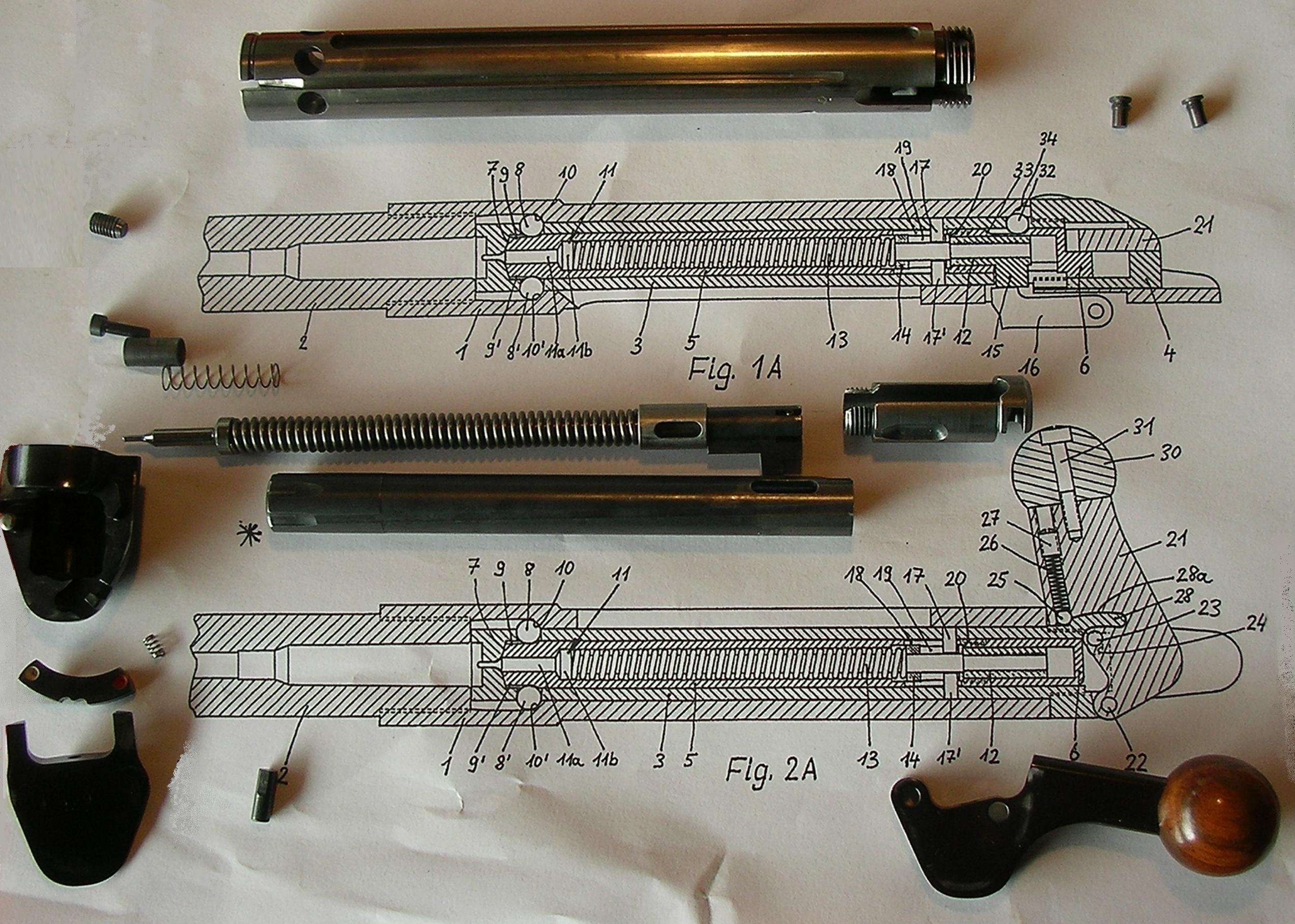 heres that cutaway again, it is in the �locked� configuration, where the groove in the cam pin doesn�t line up with the balls- and �unlocked�, with the right registration pin offset; this allows the plunger to telescope into the casing, pushing the paintballs out the front.  I�ve been 3d printing prototypes, and� goddamn if everything isn�t working out great on the first try. What the gently caress, this never happens here�s the wee sleeve, uses six 2.5mm bearings for the lug system. Very surprising how robust a system it is, given the fact that it�s all 3d printed components; I could get away with just 2 or 3 bearings I bet. Also assembling this thing is a nightmare, had to fix all the balls in their seats with blu-tack for it to work  but yeah, the bearing lug system just� works, correctly, more or less. I was sure it wasn�t gonna come together, not on the first try. And yet!   (need to limit the registration pin�s travel so it can�t fully slip out of its slot, that and play with tolerances to get a reliable unlocking action. but goddamn if my first crack at a ball bearing lug system didn�t come together nicely) here�s how you use the thing. Once the registration pin is fully seated in the slot in the breech the plunger is unlinked from the registration pin and is free to �telescope in� with a firm push. If it�s misaligned the pin offset will be wrong and it won�t unlock, if the pin is pressed accidentally during handling it won�t unlock, etc. we�ll see how ironclad that is with some field-testing  next step is coming up with some sort of auto-deploying cap or cover for the loader chambers, so sand and crud can�t get in there and possibly get fired downrange along with the paintballs. Given that, I can see a brace of these clipped to a belt/bandolier actually being practical and useful for play. For very particular use of the term �practical�, anyways. Ambrose Burnside fucked around with this message at 00:14 on Oct 30, 2021 |
|
#
?
Oct 30, 2021 00:10
|
|
|
^^That's cool as heck I love your posts^^ Does anyone know if there is a way to make Fusion 360 export 'Component Name' in one cell and the dimensions under 'Bounding Box' from the component properties into separate cells in excel for all components at once? That would sure make generating cut/parts lists a ton easier instead of having to name each component with it's dimensions (which may change as the design changes). It looks like there is a plugin/app thing called Bommer that may do this, anyone tried it?
|
|
#
?
Oct 30, 2021 20:36
|
|

|
Nice job on that paintball speed loaded! Random SW question, I'm having an issue with motion in a sub assembly propagating to the main assembly. I have a hinge with a couple of configurations: open, closed, moveable. Within the hinge assembly the moveable configuration lets me drag the free part to any angle, but once my hinge assembly is in another assembly as a component it's frozen when I try to drag and move it, I get a "selected component is fully defined" error, even though there are no constraints in the top level assembly to the free leaf of the hinge. I swear I've done this exact thing before and have no idea why I'm having problems this time.
|
|
#
?
Oct 30, 2021 22:10
|
|
|
meowmeowmeowmeow posted:Nice job on that paintball speed loaded! Within the top level assembly, set the sub assembly to 'solve as flexible'. Do this by right clicking on the sub assembly and going through its properties until you find it, or in newer versions it's a toggle available in the context menu that appears when you right click on it.
|
|
#
?
Nov 1, 2021 02:01
|
|

|
oXDemosthenesXo posted:Within the top level assembly, set the sub assembly to 'solve as flexible'. Caveat: Only do this after you have defined all of the non-flexible mates you want for that sub-assembly in the top-level assembly or you'll get some weird behavior when applying otherwise normal mates. I've had parts fling themselves 300 miles away in model space just because I applied a concentric mate between mating bolt holes in an assembly for some reason because of this (instead of applying coincident/etc. mates first maybe?). Either way it's aggravating and only happens when an intended-flexible assembly is in "solve as flexible" mode.
|
|
#
?
Nov 1, 2021 14:02
|
|
|
Lol good point. The model that meowmeow described sounds simple enough I wasn't going to mention that but yeah, SW's mate system is a shitshow. You'll learn real quick which order to mate things in to avoid launching parts off screen, and I frequently resort to just fix mating parts temporarily while setting up the real mates. Kinda like clamping work pieces while you assemble them. The one upside of all that instability is that if you're designing a complicated mechanism and it freaks out in cad, then it's likely it's underconstrained in reality as well. Typically for assemblies that are going to be fabbed I'll avoid using reference geometry for mates and only use the surfaces that will interact physically. I've caught a ton of mistakes over the years by doing that. All bets are off if you use limit distance or angle though.
|
|
#
?
Nov 1, 2021 18:54
|
|
|
Thanks for the advice and solution, I haven't tried it yet but sounds like it'll work. I swear this flexible behavior used to be standard, I've had some pretty complex mechanism assemblies before and never had this problem but haven't used this computer and install much yet. I really don't get why solidworks flings things when you adjust mate parameters, it usually gets things in the right space the first time but man you flip the orientation of a concentric mate and it'll throw the part into the next state even though it just got it ballpark correct when you first set it up. Like getting bolts in the right spot when toolbox doesnt do it right, I'll throw in a concentric and it usually gets the head close but facing the wrong way and instead of inverting inside the bolt model space it just puts it wherever the gently caress it so chooses. I've been using a lot of reference geometry and running mates off of reference planes with distance mates and stuff in early design phases when I know big picture how I want stuff to fit but haven't drawn the connectors and brackets and stuff and then start replacing my reference mates with actual constraints based on how it'll go together, and its a pain to go and re-mate the assembly but it helps me keep things where I want as I adjust dimensions without stuff breaking but also helps me not miss lineup errors that would make the thing not assemble in real life. I wish I was a little more confident in using reference mates and references running between different parts to drive more dimensions auto-magically for things like support beams and the like but it always seems to end poorly. I also feel like I recently figured out the point of driven dimensions, they always confused the poo poo out of me but are super useful to note out a couple of key measurements that aren't how you want to define the part but are helpful as reference measurements and not having to reselect geometry for the measure tool for the sixth time in five minutes. Same with editing parts in place in an assembly, with some good section view placements its great for getting clearances and stuff right without a piece of paper of random dimensions as a reference list while tabbing between a ton of different parts.
|
|
#
?
Nov 2, 2021 00:49
|
|
|

|
| # ? Apr 27, 2024 21:22 |
|
|
You may or may not be pleased to know my work pays £££ for NX and it has many of the same constraint issues. Some days it just seems to be determined to gently caress with you, orienting every part back-to-front and then flipping entire assemblies around to align them with the widget you just added. I wish there was a way to force behaviour by selection order or something, like always move part 1 to part 2, because the way my brain works 99% of the time I'm grabbing the 'loose' part first then trying to constrain it to something I perceive as 'fixed'.
|
|
#
?
Nov 2, 2021 14:10
|
|
