|
Time to go full Archimedean Dynasty.
|
 #
?
Nov 12, 2018 15:36
#
?
Nov 12, 2018 15:36
|
|


|

|
| # ? Jun 15, 2024 03:12 |
|
|
Spoiler-Blocking Headphones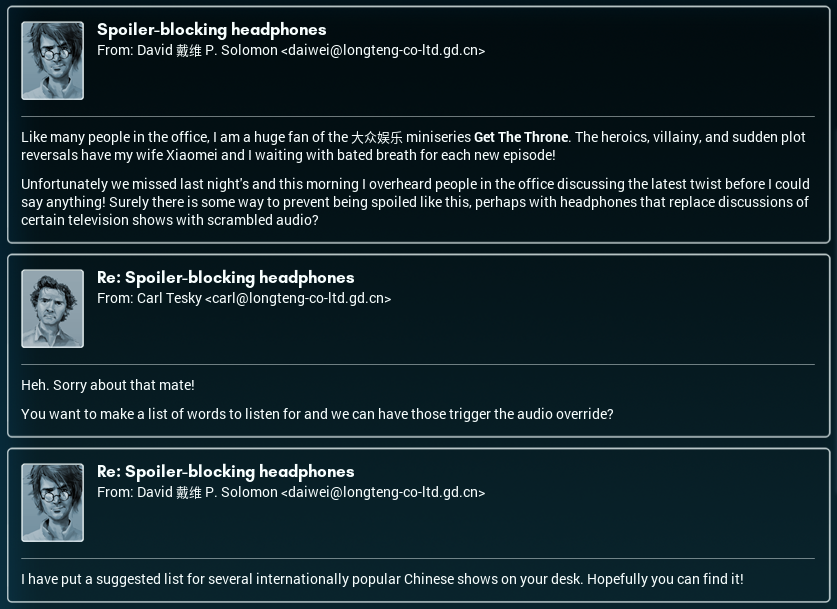 I've seen billboards for Get the Throne around town. If I had to describe it, it'd be Romance of the Three Kingdoms meets what Hollywood did to Arthurian legend over generations. A lot of the other people at the office are fans of it. Me? Well, I'm more one for Lamia's wacky hijinks. Now, let's see what David's come up with. 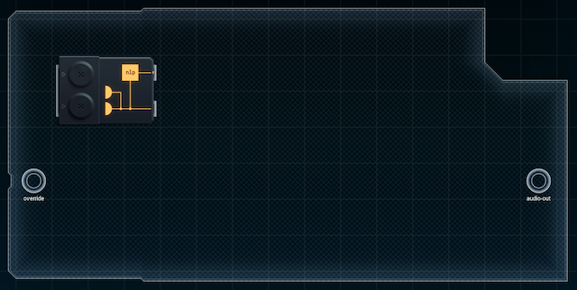 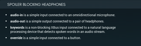 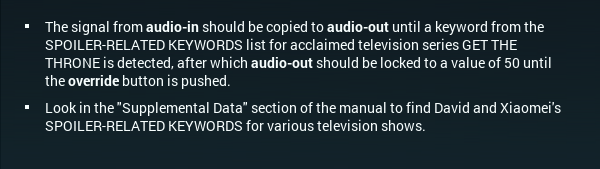 This is an interesting idea. The design would have to store a predefined list of keywords from David's big list (which I haven't actually located yet). Then� well, the surprising part is that the headphones have to be passing audio through most of the time! (Naively, I thought the headphones would just play static or do something noise-canceling when they spotted a keyword, but not that they'd relay audio entirely the rest of the time and stay silent. I guess this way was easier to design... presumably, you can just have the headphones block out all outside sounds with insulation, and then the relay design makes sense.) A look at the datasheet of the natural language chip stirs things up a bit more. 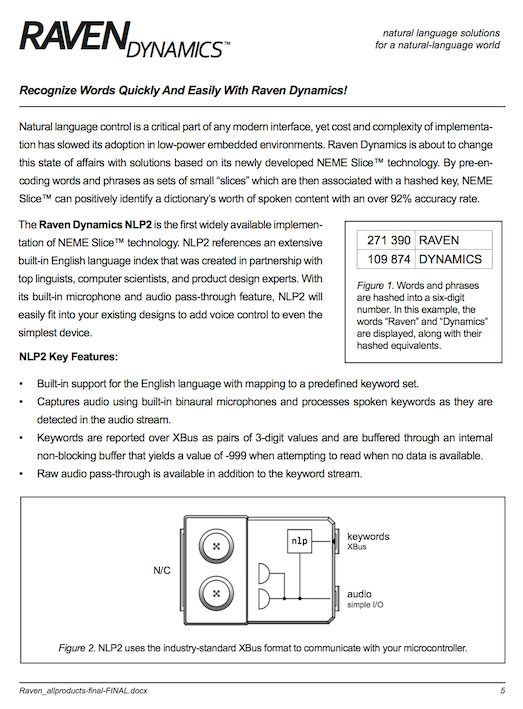 Once again, David's designing for the international market. This is an English-language NLP chip - so the people who'll purchase this are TV-watchers who, not only speak English, but have English spoken around them by other people. He did pick internationally popular Chinese shows - but this could also easily be adapted for NA shows simply by swapping out the keywords of Get the Throne, with ones from, say, Ms. Broom's Time Police, or maybe Back Stab. The keywords will almost certainly be stored on a memory chip of some kind, so all that needs to happen is that the memory chip goes into a swappable card - put a slot in the headphones to fit? - and then we can sell new cards as new shows come out (and the headphones'll remain useful to boot). So: let's see this list of his.  There's Get the Throne, second from the top. Truth Investigators made the cut, which isn't surprising at all. Lili's a big fan of that one - very tense (apparently). I hadn't heard of Memories of Tomorrow, but some Googling suggests it's very popular. ("Good at bringing all the feels", end quote.) I am a little worried if we do a card for it, though - some of its keywords seem a bit generic. And at the bottom, we have none other than Lamia! It's got... Wait... dental insurance? Dental insurance! THAT was what was in the anniversary gift that was teased in the time skip? Wait, there's only one potential supernatural girlfriend on the show who has biiig snake fangs and would really need dental insurance as a gift. Which means� �which means I've been spoiled for the season finale, dammit. And after asking everyone on here and everything! And wearing a pair of these fine headphones I'm about to design wouldn't have saved me... This is going to be one of those days, isn't it.  Anyway, here's how this needs to work. 1. Have two 'modes', as mentioned above - pass-through mode and silent mode. I'm thinking it's probably best if one MC is responsible for passing audio through (or not) while another MC handles keywords. 2. In pass-through mode, the keyword MC checks keywords against the memory chip that has the values in David's list. (The prototype in my simulator doesn't show the card slot, but I'll mention it to David when I email him the final design.) If something trips it, switch the audio MC to silent mode. Otherwise, the audio MC sends audio to the speaker. 3. In silent mode, the audio MC stays silent until the Override button is pressed. Then it goes back to pass-through mode. The keyword MC doesn't have to do anything at this point. I'll craft the design to this spec and see how it performs. [ ~ ] This design came slowly. I'm not really feeling as motivated ever since I saw the bottom of that list... anyway, here it is. 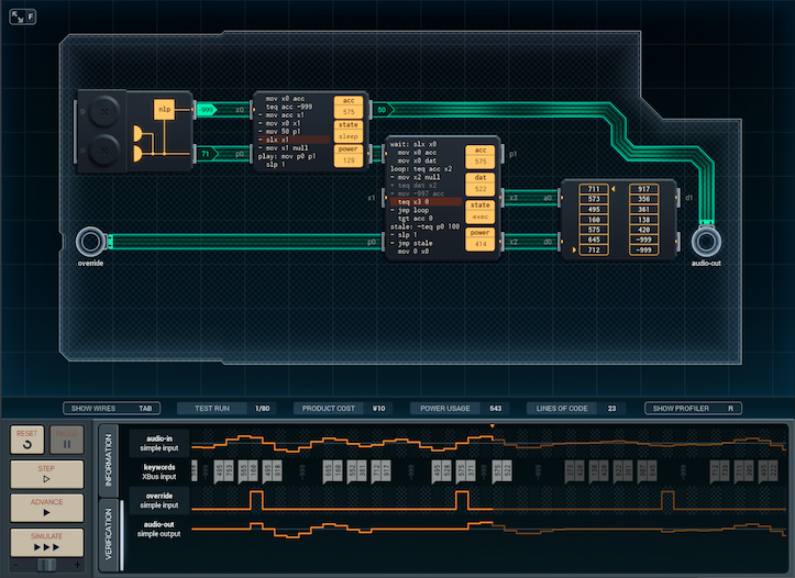 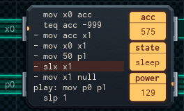 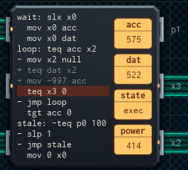 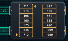 The small MC is the audio MC, which passes keywords through to the big MC (the keyword-checking MC). If the keyword-checking MC doesn't find anything, it'll report "all clear" to the audio MC, which happily passes sound through to the speakers. If a keyword is found, though - that's where it gets interesting. Basically, the audio MC's "slx x1" means it can wait indefinitely for the "all clear". If the big MC sees a keyword, it just stops (once it's tested against the whole memory chip) and waits for the override button to be pressed - whereupon, it sends 'all clear' to the audio MC, and everything returns to normal. The memory chip just contains David's Get the Throne keyword data in no particular order (the first and second halves of each keyword are grouped together). As is, it's �10 and 1188 average power, but I'll keep fiddling with this design to see if I can improve it - in particular, there is one bug I can potentially see, where the NLP chip stores (potentially spoiler-related) keywords in its buffer while the audio MC is shut down. When the audio MC resumes after an override, those spoiler keywords (which took place during the part of the conversation the user wasn't listening to) get passed to the keyword MC, shutting everything down again. This won't be a problem if the user holds override down for a few seconds - the NLP chip's buffer can't be that big - but it's an edge case that's worth looking into. [ ~ ~ ] 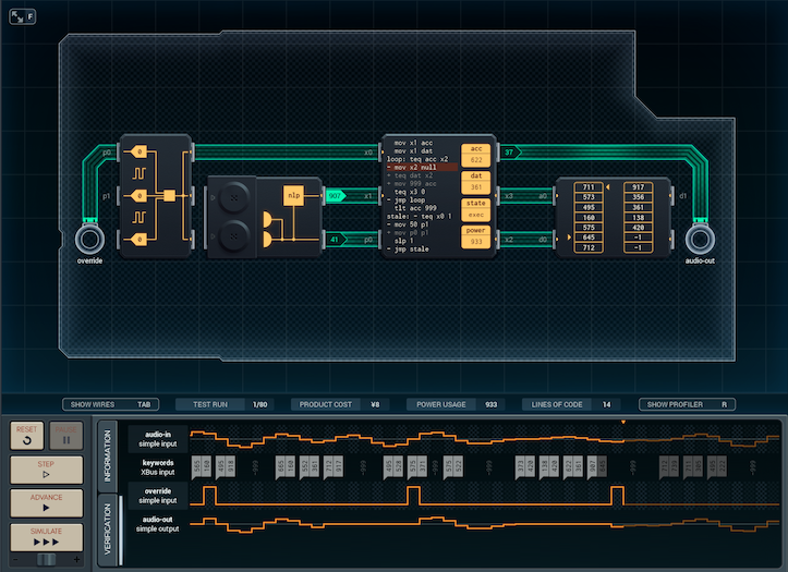 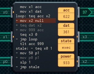 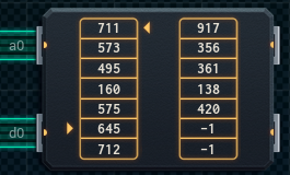 I fixed the bug, but I kind of made it less efficient. It's �8 and 1422 average power per run now - and the reason for this is that it keeps testing for keywords once per time unit, even if the audio pass-through is shut off. I had to change the unused slots in the memory chip from -999 to -1 so that the design doesn't think a lack of keyword data ([-999,-999]) is a spoiler and silence it. In the same vein, the input expander is there for the sole reason of not needing to use another simple input pin for the button. This change does sort the bug out simply because keywords are always tested, and I did save a MC that way. But, at the same time - the old version would skip the test phase if it saw a -999. This version doesn't do that (no space for more code), so it'll test a lot of "keywords" that are really just [-999,-999] when the NLP chip isn't detecting. So because of both the additional keyword tests and the testing of blank input, this design ends up drawing more power. Which version is best? For once, I can't say that I've made a specific improvement in the design, just a change. This version draws more power, but is more responsive to the override button. But, depending on how it sorts out with hardware and what sort of battery can go into it, the other design could be better! If the power draw in this version is too big, a too-short battery life could dissuade people from using (or buying) the 'phones. This is the sort of thing that needs real-life testing. I'll send both designs to David and he can figure out things with the factory from there.  Sorry, David, but no one is getting out of this alive. Now, I'm gonna go home, get some popcorn, top it with some of the cheese Carl gave me, and watch the season finale of My Roommate Is a Lamia!... and I'm gonna like it. 
|
|
#
?
Nov 14, 2018 12:16
|
|


|
I'm honestly relieved. With those contact lenses and the wing props and that verbal tic, the Succubus lady somehow just fell on the creepy side of cute.
|
|
#
?
Nov 14, 2018 13:56
|
|


|
I'm gonna have to rewatch the early seasons of Get The Throne. I'd forgotten all about the Dwarf Rebellion! I remember, the v1 releases of the fansubs I used were off, because the translators couldn't believe it was really a rebellion of dwarves, so it got rendered as "small uprising", which had the wonderful effect of making all the dialogue in the council scenes seem really understated. "Your Majesty, dire news! There is a small uprising!"
|
|
#
?
Nov 14, 2018 15:53
|
|

|
I'm still impressed at just how perfect of a caricature David is of that certain type of expat.
|
|
#
?
Nov 14, 2018 20:03
|
|

|
The_White_Crane posted:I'm gonna have to rewatch the early seasons of Get The Throne. I'd forgotten all about the Dwarf Rebellion! That's dwarf sizeism, that is.
|
|
#
?
Nov 14, 2018 20:43
|
|

|
Carbon dioxide posted:That's dwarf sizeism, that is. 
|
|
#
?
Nov 14, 2018 22:04
|
|
|
Cool Dad Is Back!  When Joe tries to slap you on the back, duck. And no, I'm not going to Google and see if DJ Like and DJ Subscribe are real pop artists. Tombot posted:Maybe Sun Haotian is just a shell company for Andrew Ryan. TooMuchAbstraction posted:I guess a submerged city also has room for six-way intersections. Maybe site it near a volcanic vent for geothermal energy? Still going to be hellaciously expensive, but maybe not as expensive as a spaceship would be. paragon1 posted:What if it's not next to the ocean? What if it's IN the ocean? OK, hang on. A submerged city would explain the deep-sea stuff, but I can see some issues with it: � The whole nitrogen-and-the-bends thing. Wouldn't the residents of an underwater city be subject to that? � If your containment shell (outer dome) fails, everyone dies horribly. If your air supply machinery fails, everyone dies horribly. I can think of a few other scenarios of similar issue. � Why go to the trouble of putting a whole city deep underwater when you could find a nice stretch of continental shelf? � Why build a submerged city big enough to use cars? Could you really support everyone just from those aquaponics modules I whipped up? � Basically, I'm not sure what the benefit of putting it all underwater would be. It sounds cool, but in practice... Junpei posted:What if it's just a city that floats on top of the water? That could work. There's a lot of unused space in the oceans, and there's not the issue of the immediate fail conditions that underwater city-dwelling would have... it still boggles the mind. One stumbling block, though - what about fresh water? You'd need a lot of energy to run desalination constantly, and a city would NEED a lot of fresh water. (While we're on the subject, I once read an article that pointed out that almost every city on Earth has been founded around water sources!) ashnjack posted:I still think this whole thing is for an automated military sea base. I can see a lot of the automation implying a lower population. If it were a military project, though, wouldn't we be talking to representatives of China's military etc. instead? Mr. Haotian is pretty powerful, but he's more CEO than general. And if you put a military base out on the ocean, you'd better have something out there worth guarding. The Pacific Ocean is a big place, and most of it is fairly uninteresting. The_White_Crane posted:I'm gonna have to rewatch the early seasons of Get The Throne. I'd forgotten all about the Dwarf Rebellion! It sounds like those subtitles had a little problem...
|
|
#
?
Nov 30, 2018 12:56
|
|

|
Would You Believe It? That's... not where I thought that sentence was going.  OK, that honestly sounds like a cool idea. You could probably partner with other groups for this, too, not just athletic wear places - fashion houses, that sort of thing. And it sounds pretty simple, on the surface! Mind you, if I've learned anything in this job, it's that the complicated things are simple, and the simple ones are complicated. 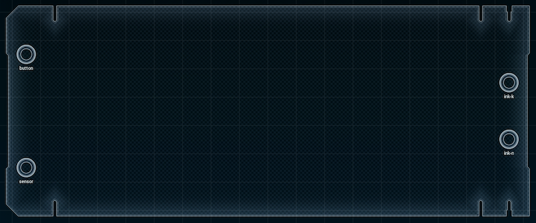 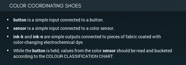 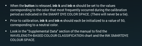 Oh. Oh dear. This is what Joe meant when he said automatic. So, just to recap, here's what I have to do, broken down into computer-friendly steps: 1. While the button is pushed, read sensor values and store them in a memory chip. 2. Once the button is un-pushed, turn those sensor values into color-bracket values and store them again, probably. 3. Figure out what the most populous color-value is. 4. Set the ink outputs to that color, according to this chart: 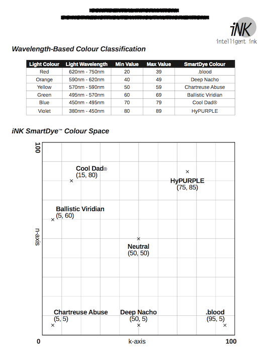 I don't know what 'n' and 'k' are supposed to mean in this context, but it does seem like the colors are arranged in a formation _kind of_ like the RGB color wheel. This is definitely going to be a long and involved project, so I'll upload progress reports. But the result is going to be worth it...! [ ~ ] 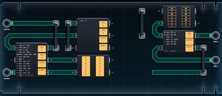 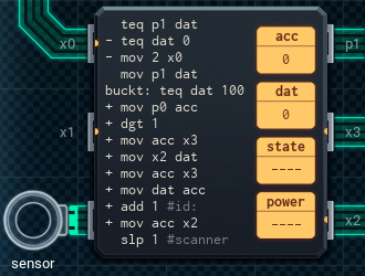 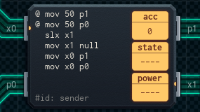 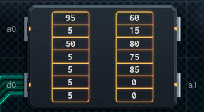 Here's my initial extremely prototype version. I've got the 'playback' chip on the right, which takes color (n and k) values from a ROM chip when signaled, and sends them to the outputs. (If you're wondering why there's no connection to the address line of the memory chip: another chip is going to set the address, and then the playback chip just reads the two values). On the left side, there's the primary bucketer MC. As long as the button's held down, the MC will read from the sensor, divide the value by 10 using dst, and add 1 to that cell of the memory chip. (So a value of 20-29 increments cell 2, 40-49 increments cell 4, and so on.) Once the dust settles and the button is released, it'll send on x0 to let the next MC know it needs to read the memory chip and find the highest value. (An interesting side effect of this design is that red color values, which have the sensor numbers 20-39, occupy two slots in the memory chip, so the next MC will have to account for that.) I still have to construct the MC which'll find the highest value and translate it into the correct color address for the color-values ROM, so that's next. I also need some way of erasing the sensor-connected memory chip once the color is passed to the output - this is so that the user can push the button more than once and the new sensor values don't have to compete against the ones read the first time. If I didn't erase the memory, the user would have to hold the button down longer and longer each time for it to read properly! [ ~ ~ ] 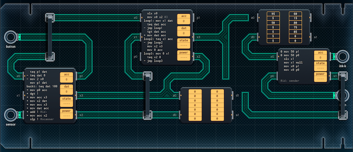 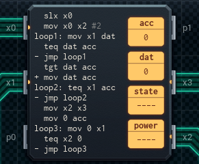 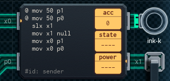 I finished the second MC (the big one in the middle - I'm calling it the maximizer MC). It's responsible for figuring out which color value is highest (most common). The thing is, the design of the memory chips makes that... difficult to do. The way you'd normally program an algorithm to find the biggest number in the set is to keep one variable that had the the highest value, and another for that value's position. You loop over each item in the set. If it's bigger than the biggest value we've seen so far, it becomes the new biggest, and we update the variables accordingly. The problem here is the memory chip's address pointer, which increments after each read. So, if you compare the current cell in the memory chip with the register holding the biggest value, you'll need to reset the address pointer to actually store that value later. Each address pointer reset is three lines of code ('mov x2 acc / sub 1 / mov acc x2), and the resulting algorithm is too big to fit, even in a MC6000. What I ended up doing instead is to work with the memory chip, rather than against it. The MC takes things in two passes. In the first pass, the MC moves each item in the memory chip into dat. acc is used to store the largest value seen so far. If dat is bigger than acc, it gets copied to acc immediately. The pass finishes with the biggest value in the memory chip in acc. There'll never be a tie, so if the MC happens on one, it knows it's gone around the the entire chip and it can stop. (This isn't that efficient, but I'll focus on improving the code in a later prototype.) The second pass looks through the memory chip again to find that biggest value. When it finds it, it sends the address of it to the third MC, on the right. In theory. This design has a few problems, and I'm going to list what they are. First off: I don't have enough spare pins on the maximizer MC to send the address value to the ROM with the color values and notify the MC on the right that sends those color values out. If I connect the middle MC, the right MC, and the ROM chip in a three-way connection like the pic above suggests, the memory chip will always snap the MC on the right out of its slx, because it always responds when anyone tries to read data. So, I might have to turn the MC on the right into a MC6000 so it can set the right address on the ROM chip itself. Second, there's the little issue of the color red taking up two buckets. If you check on the datasheet above, you'll notice that values from 20-39 (a 20-item-wide set) are what the sensor gives when it sees something red. All the other colors only have 10-item-wide sets (40-49 for orange, 50-59 for yellow, and so on). Since I'm using dst to divide the sensor value by 10, then converting that directly into a memory address, red values will end up being put in cell 2 or cell 3 of the memory chip. I was originally intending to resolve this by putting code to sort it out on the middle MC, but it's full - which leads me into my third problem. Third is the little issue of erasing the memory chip once the color has been passed to the output. I said in the previous section that I needed some way of erasing the memory, and the 'third pass' ('loop3') at the bottom of the maximizer MC is it. The only problem is that I don't have space to set the address on the memory chip beforehand, so it just erases the part of the chip from 'wherever the address pointer was' to (currently) the start, which might not be the whole chip under a lot of circumstances. I might not have enough space to do the erasing justice here. I'll keep working on the design, and post another section when there's improvements. [ ~ ~ ~ ] 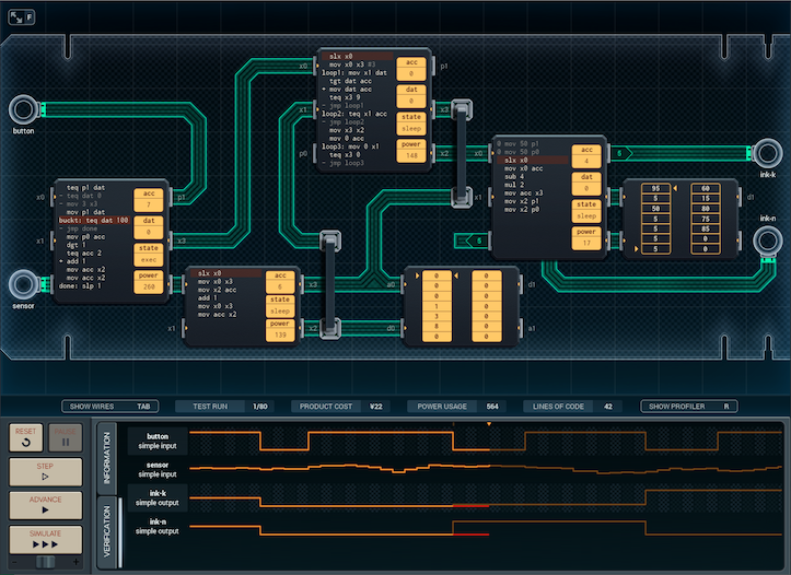 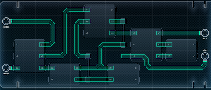 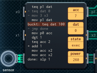 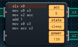 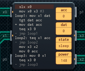 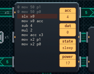  This prototype works! Sort of. I was able to solve some of the problems, but not all of them� not yet, anyway. I had to split the design of the initial bucketer across two MCs (both of which are on the left). The small bucketer MC, when given an address, reads that value from the memory chip and adds one to it. Then it stores the added-to value back in the same cell. (Assuming you pass it the same address twice, which the big bucketer always does). The extra space lets the big bucketer MC do one extra job: if the memory address to add to is '2', it bumps it up to '3' instead. This solves the problem of red having two separate buckets. As I suggested above, the output MC (on the right) has been upgraded to a MC6000 (mostly for the extra pin, which lets it use two to talk to the ROM chip). It now takes the ID number of a color, fishes up the appropriate pair of cells from the ROM chip, and outputs them to the ink-n and ink-k outputs. The only problem I haven't quite solved is erasing the memory chip once everything's properly output. The maximizer MC, in the middle, has had the first loop made more efficient, but I haven't seen any way to save the one line of code I'd need to get the erase to cover the entire chip. (The extra line would let me set the memory pointer to the start and have the loop finish once it loops back to the start. Right now I can only do one or the other.) Because of this, the memory chip doesn't get erased - meaning, the prototype works the first time you press the button after powering it on... and then it stays stuck that way until you reboot it. I'll take one more crack at the design and see if I can fix this. I'm really close - I can feel it! And just as well, 'cause this one has been quite the struggle to put together. [ ~ ~ ~ ~ ] 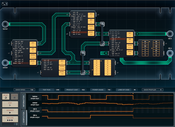 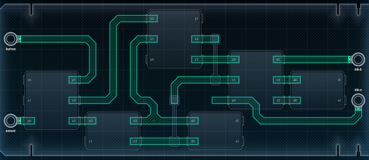 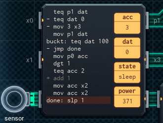 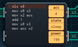 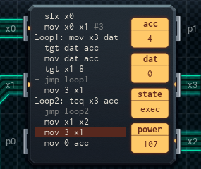 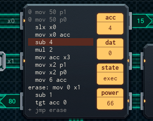  Sometimes the solution is staring you in the face, and you don't even notice. It was pretty straightforward: [1] Move the erasing code to the output MC, which means it has to have a connection to the data pin of the memory chip. [2] Connect the one unused pin on the output MC to that data pin. It makes sense if you think about it - erasure only needs to be done after displaying the color, so it's the perfect place to put those lines of code. And I was able to use the freed-up space on the maximizer MC to make its second loop (the one that finds the position of the biggest value) only look over the part of the memory chip that's actually used by the shoes. And with that - it's done! �22, 1043 average power. Honestly, it feels like I was working on that one for weeks! Joe's ideas tend to need more engineering than usual to put together, but I'm sure he'll love this. And honestly, I might buy a pair of these myself, once they hit the stores...  Ooh, tracksuits would be interesting. There's the little question of the washability of e-ink fabric, though. And how would you keep the control circuit safe on its trip through the wash, for that matter? Still, that's a problem for the hardware design side of things - not me. P.S: My secret project is almost done, and I'm getting excited to share it with all of you! Here's a sneak peek at what to expect: 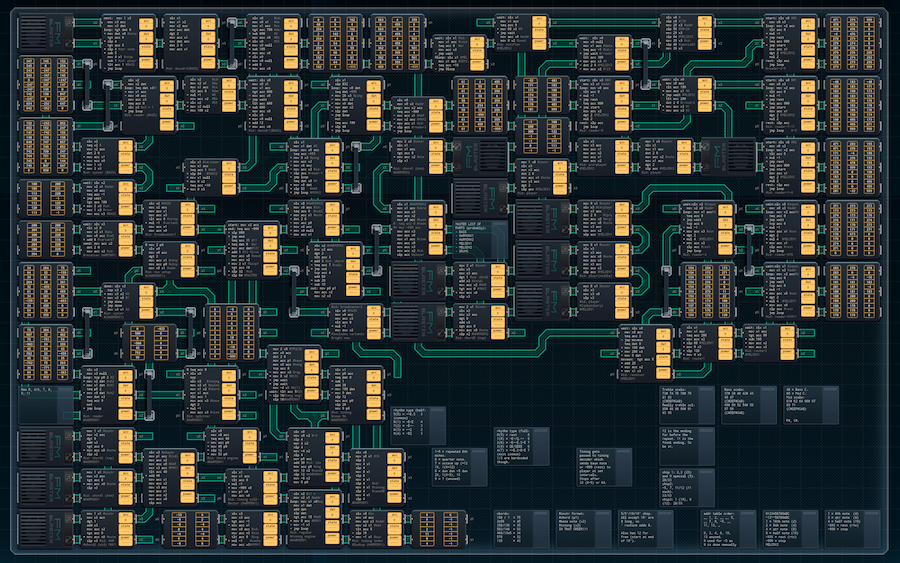
|
|
#
?
Nov 30, 2018 12:56
|
|
|
Wow, things are getting complex. That's a pretty tough problem considering the constraints you're operating under. I seem to recall hearing of devices that can generate electrical power from impacts, which leads me to wonder if you could install some kind of micro-generator that kicks in when the wearer puts their foot down, and use that to run the chip / power the LEDs. The scale of power generated vs. what you need is sadly probably not a good match though. 
|
|
#
?
Nov 30, 2018 23:01
|
|

|
TooMuchAbstraction posted:Wow, things are getting complex. That's a pretty tough problem considering the constraints you're operating under.
|
|
#
?
Dec 1, 2018 00:09
|
|

|
The important information here is that Joe does indeed wear a tracksuit seven days a week.
|
|
#
?
Dec 1, 2018 00:23
|
|

|
Hey engineers, advent of code has started again. It's a daily coding puzzle for every day from now until christmas. https://adventofcode.com/ Now, usually the puzzles don't get impossible hard for anyone with access to a high-level language and some coding experience. But I was just thinking. Wouldn't it be a real challenge to solve these in the Shenzhen I/O sandbox? Personally I'm not gonna try, I don't have the patience. I'll just try doing them using a language I am good at. But someone who comes up with poo poo like this: Someone like that might be interested in a challenge like that. Or just other folks who follow this thread. If Quackles is okay with this, I'd say, if anyone wants to do any of the advent of code puzzles, feel free to post your solutions here. A very tricky part might be getting around the fact that those coding puzzles don't limit themselves to the [-999, 999] range. Happy holidays! Carbon dioxide fucked around with this message at 12:53 on Dec 1, 2018 |
|
#
?
Dec 1, 2018 12:51
|
|
|
Carbon dioxide posted:If Quackles is okay with this, I'd say, if anyone wants to do any of the advent of code puzzles, feel free to post your solutions here. This sounds like a really great idea! For people who have more digits than will fit in a register: you can always output longer numbers over multiple XBus packets. (So, -1048576 could become [-1],[048],[576]). If anyone has custom specs for the puzzles, please feel free to post those here as well. ")
|
|
#
?
Dec 2, 2018 00:19
|
|
|
Quackles posted:
*Nope! You're not breathing compressed air! Assuming you enter and leave via submarine, there's no reason at all for you to ever be breathing air at anything other than a normal pressure, so that simply wouldn't be an issue. *Ship and submarine design (think bulkheads and water tight interior compartments) already offer a lot of potential solutions to these problems. I'm not actually sure what could threaten your outer "hull", since you'd already know all the math for the pressure you'd be dealing with, outside of an undersea volcano or huge earthquake or something. Yes, there'd be increased risk from certain kinds of factors, but I can think of a few ones we have to deal with hear on surface world that'd be partially or totally mitigated. Storms, wildfires, air pollution, landslides, attacks by neurologically enhanced chicken swarms, etc. *Well I myself certainly never ruled out a continental shelf placement, but presumably because there's something specific on or near the deep ocean floor that you want easy access to. Mineral exploitation comes to mind. Or because you want to make external access more difficult. An oceans worth of water would provide one hell of a shield from external attack as well. Or maybe he's secretly a vampire and wants to finally make himself absolutely, 100% safe from the sun. Lots of potential reasons! *Who said the intersections are for cars? There's a whole lot of devices you could use to move people around in a city built from scratch, and they don't necessarily have to be much bigger than an adult male human unless you're dealing with large machinery or freight. I don't see why your aquaponics setup wouldn't be able to feed if the planners were sufficiently ambitious in their scaling. For that matter, why would your aquaponics setup be the only food source? The thing would be in the ocean, which is a somewhat notable source of food. Yeah it's a crazy idea. I don't think it's really all that likely. But when it comes to motives and practicality, well... Humans have done far more impractical things for much less potential material gain. Just look at the moon!
|
|
#
?
Dec 2, 2018 06:28
|
|

|
Hey Sexy.. I'm not sticking my lower anatomy anywhere near heavy machinery, no matter how good-looking it is. TooMuchAbstraction posted:I seem to recall hearing of devices that can generate electrical power from impacts, which leads me to wonder if you could install some kind of micro-generator that kicks in when the wearer puts their foot down, and use that to run the chip / power the LEDs. The scale of power generated vs. what you need is sadly probably not a good match though. No clue! I did know a friend once who made light-up shoes for a cosplay costume. They put battery packs in the tongues of the shoes. Maybe there's potential in that direction? paragon1 posted:Yeah [an underwater city]'s a crazy idea. I don't think it's really all that likely. But when it comes to motives and practicality, well... Humans have done far more impractical things for much less potential material gain. Just look at the moon! That's certainly true. Humans do have a habit of doing crazy things because they can. That said, I get the feeling the wraps are coming off Mr. Haotian's big project soon, so I'm sure we'll see what it is.
|
|
#
?
Dec 13, 2018 11:22
|
|
|
Airline Cocktail Mixer This sound like an interesting idea. Useful, too. I wonder if this would be aimed more at first class or coach travelers? Mind you, if you're flying in super-mega first class, you've probably got your own private bartender, but this seems like it'd do the job across the board otherwise. (As a side note, Carl's not wrong. See? Joe has sobered up.) 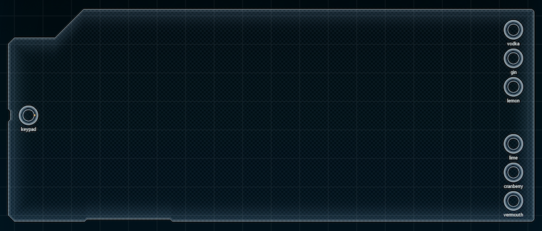 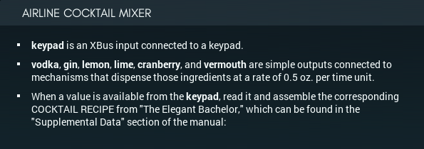 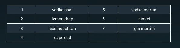 Looking at the spec, it's pretty simple. Get the number from the keypad, output a pattern of matching pulses that matches the recipe from the book: 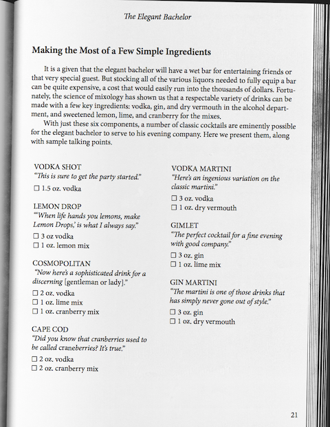 The way the nozzles are set up turns "1 oz" into 2 time units, "1.5 oz" into 3, "2 oz" into 4 time units, and "3 oz" into 6. For those wondering, the spec is set up such that the machine should dispense any liquor (vodka or gin) and mixer (lemon, lime, cranberry, vermouth) at the same time - it can't dispense them one after the other. 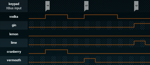 Effectively, this is the big brother of the meat printer from earlier, and I might be able to solve it the same way: with logic gates. My first attempt is going to definitely be using logic gates, in order to save as much power and (hopefully) cost as possible. Worst case, I'll have to use a PGA33X6 instead, or ditch the gates and put the drink-serving conditional logic in software. But for now: Logic ahoy! (PS before we start: Aren't those lines in the book corny?  I didn't know the thing about the I didn't know the thing about the [ ~ ] My mental blueprint for the logic gate versions was as follows: [1] Get a MC. [2] Hook that MC up to a memory chip so that it can output 3-line patterns (one for each drink), with the help of an expander. [3] On receiving an input, turn on the vodka (or gin) output, and pull the appropriate pattern from the memory chip and push it to the expander. (The expander will be connected to the logic gates, which'll go to the mixer outputs.) [4] Wait the right amount of time for the mixers, then turn off the mixer output. Then wait more, then turn off the liquor output. Done! So, I created a setup that did just that. The only problem ended up being the amount of space left for the logic gates: 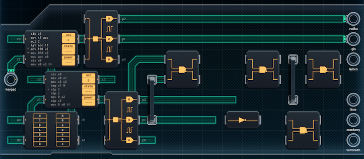   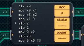 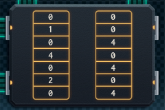 The top MC listens to the keypad and outputs the 'vodka' or 'gin' pattern to the top expander. Then it passes the keypad value onto the lower MC, which reads the right output pattern from the memory chip (the patterns aren't in yet - I can't know what to put without wiring up the logic gates first) and outputs it to the lower expander, which should connect to the outputs via the gates. The pattern of gates I came up with required four AND gates and a NOT gate - you can see them in the pics above. The gates were to be wired up to the lower expander as listed: Lemon = P2 AND ~P1 (the ~ means NOT, so ~P1 means P1 is off.) Lime = P2 AND P1 Cranberry = P0 AND P1 Vermouth = P0 AND ~P1 This would let an output of [1,0,0] dispense lemon, an output of [1,1,0] dispense lime, an output of [0,1,1] dispense cranberry, an output of [1,1,1] dispense both lime and cranberry, and an output of [0,0,1] dispense vermouth. The only problem is that I played around with the gates, and I am very sure that four large, square AND gates (plus wires) won't fit. Which brings me to my actual solution: 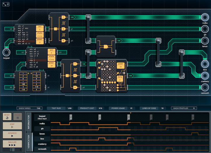 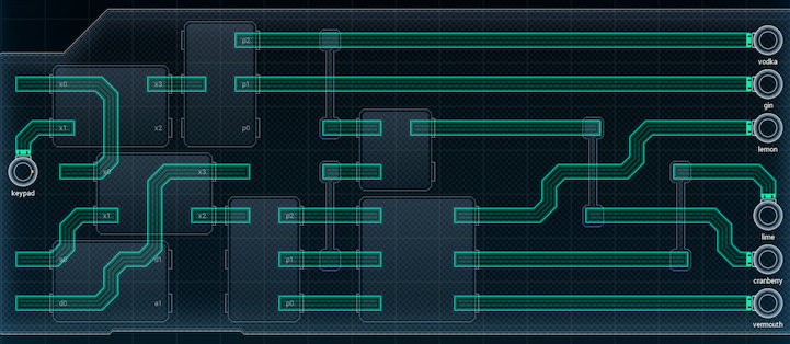 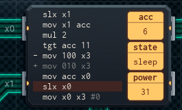 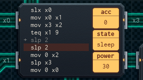 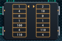  It's basically the exact same design, but the logic gate section has been redone, with most of the gates replaced by a PGA33X6. I also got a bit clever - since the PGA is three-inputs-to-three-outputs only, and we have four mixer outputs, I had to base the fourth output on something, and the fact that cranberry is only used by vodka-containing drinks made it easier. (Also, this pattern setup saves some power with the PGA, compared to connecting to cranberry to P0 AND P1.) The logic setup, from both the PGA and the AND gate, is now as follows: Lemon = P2 AND ~P1 Lime = P2 AND P1 Cranberry = 'vodka' AND P1 Vermouth = P0 AND ~P1 An output of [1,0,0] dispenses lemon, an output of [1,1,0] dispenses lime, an output of [0,1,0] dispenses cranberry if 'vodka' is on ([1,1,0] with 'vodka' on will dispense both lime and cranberry), and an output of [0,0,1] dispenses vermouth. (There's a few more things about the memory chip I should explain before wrapping up this section. The numbers in the chip in between the patterns are timers - they tell the device how long to dispense just the liquor after stopping the mixer outputs. The other thing is that, though the pattern-timer pairs are in order by drink, they actually start two cells down from the top left and wrap around, instead of beginning at the top. The reason for this is that the keypad's number is multiplied by 2 and used to pull an address from the memory chip - and 1*2 = cell 2 [two down from the top left], while 7*2 = cell 14 [which wraps around to 0].) The whole contraption is �16, and uses 207 power on average, but I'm not happy with it. Mostly, this is due to the presence of the PGA33X6. Logic gates may not have fit, but I haven't tried creating the conditional logic entirely in software (in MCs) yet. I suspect it might be simpler and less power-intensive - and this device is meant to be used by flight attendants on airplanes, so it'll almost certainly be running on an internal battery. Power usage is more of a concern than cost at this point. Which means my next job is to completely throw out this design and write a lot of MC code. [ ~ ~ ] It took some figuring out and writing down patterns, but here's what I came up with: 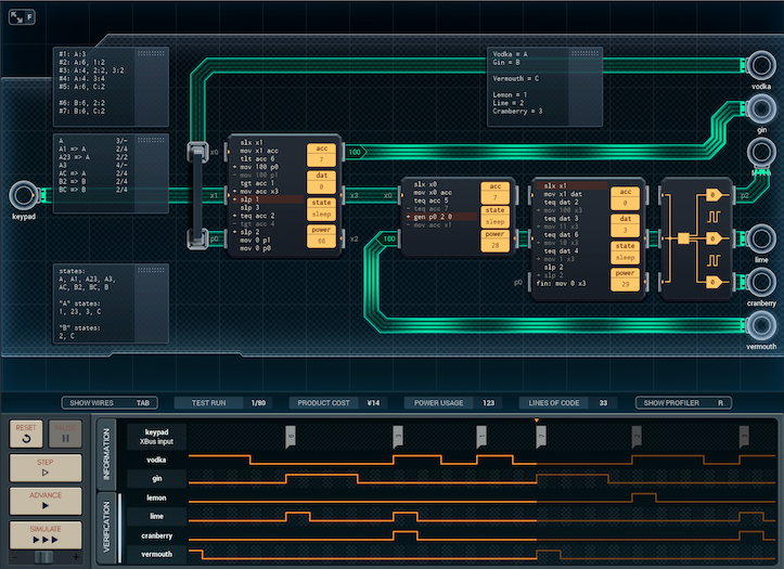 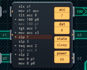 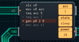 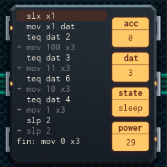 This design throws 'clever' out the window in exchange for 'straightforward'. The leftmost MC is responsible for reading from the keypad and deciding whether to turn on the vodka or gin outputs - and for how long (3, 4, or 6 time units). It then passes the keypad number to the small MC in the middle. The middle MC has one job - if the keypad value is for a martini (5 or 7), it pulses the vermouth output for 2 time units. Otherwise, it passes the keypad value along to the far right MC, which handles the rest of the mixers. The rightmost MC is mostly just a series of conditional statements. Each checks the keypad value against a specific drink order, and turns on lemon, lime, and/or cranberry in combination - then turns them off after 2 (or 4) time units. I was able to improve on the PGA version a bit with this one. This prototype is �14, and uses 191 power on average. Unless I can come up with something better (or better-optimized) in some way, that looks to be as good as it'll get. I'm going to take a bit of a coffee break before I send this version in. Just in case. [ ~ ~ ~ ] I FIGURED IT OUT! The basic idea took three minutes. It took a solid day, including writing a Python program connected to the Espresso boolean-logic minimizer library, to figure out the rest. The nub is: it looks like the logic-gate version will always require 5 logic gates. (This is part of what the Python program was there to check.) But� what if the logic gates were three ANDs and two NOTS, instead of four ANDs and one NOT? That could fit, right? It turns out (after a lot of testing, trying, and sorting through my program's output possibilities) that it all fits perfectly. 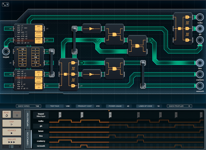 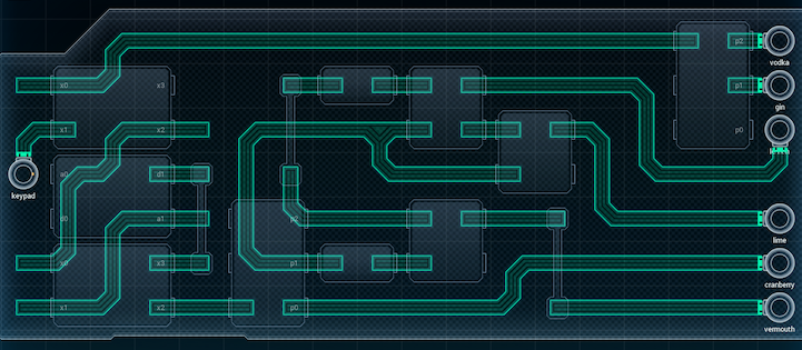 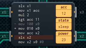 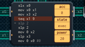 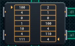 Key changes to the design include: � The upper output expander got moved over to the far right, meaning I only need to run one output line across the top instead of two. The extra space was used for logic gates. � The lower MC and memory chip have had their positions swapped, which means I can wire them to take up less space (the middle chip, now the memory chip, doesn't stick out as far right as much as the lower MC did when it was there.) � And, of course, the logic gates have been revamped. The new logic gate setup is as follows: Lemon = P1 AND ~P2 (remember, ~ is NOT.) Cranberry = P0 Vermouth = ~P1 and P2 Lime = This'll take some explaining. On the face of it, it's P1 AND ~Lemon. But, Lemon is P1 AND ~P2, so ~Lemon could be any of: (~P1 AND ~P2), (~P1 AND P2), (P1 AND P2). This is where the fact that both AND gates use P1 as an input comes in handy. The only ~Lemon combination that has P1 on and will work for the Lime gate is P1 AND P2 - which makes it the only combination that turns on the Lime output. Effectively, the whole point of chaining the AND gates was because I couldn't get separate wires for P1 and P2 to fit. For reference, [0,1,0] dispenses lemon, [1,1,0] dispenses lime, [0,0,1] dispenses cranberry, [1,1,1] dispenses lime and cranberry, and [1,0,0] dispenses vermouth. The patterns in the memory chip are updated to match. So, the new and improved version... is �15 - slightly more expensive than the three-MC version. However, it is more power-efficient, needing only 142 units of power, on average, per run. I'm so happy I could get logic gates working! And I got the power usage down, which is the most important thing. Now, time for one last once-over, and then it's going out. [ ~ ~ ~ ~ ] 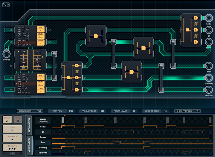 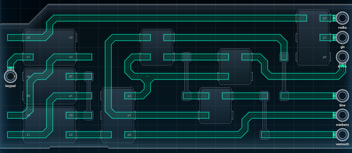 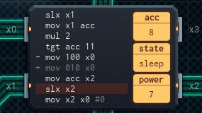 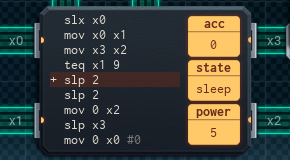 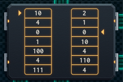 I had one last idea on how to improve the design. I think this is it. It's as perfect as it can get. The difference between this version and the last one is: I realized that I could repeat the 'chaining AND gates' thing to cut the NOT gates out from the picture entirely. Here's how it works. We have the following pattern of outputs: Output A = P1 AND P2 Output B = P1 AND ~P2 Output C = ~P1 AND P2 (I'm using "Output A-C" because I shuffled the patterns around again to make this work. I'll detail the actual mixer output assignments at the end.) Basically, each possible combination of P1 and P2 codes for a different output (except P1 and P2 both off, which codes for 'everything off'). And I can use the inverted output of an AND gate to see when its condition isn't met. So, if I have an AND gate for P1 AND P2, I can use its inverted output almost like an XOR gate, kind of. Output A = P1 AND P2 NOT Output A = (~P1 AND P2) or (P1 AND ~P2) or (~P1 AND ~P2 aka 'all off') But, if I want to use the inverted output from the Output A AND gate, I have to be able to distinguish between the three situations I listed. I can do that by piping ~A and one other input into a new AND gate. And that's what I do. Output A = P1 AND P2 Output B = ~A AND P1 = P1 AND ~P2 Output C = ~A AND P2 = ~P1 AND P2 The NOT gates are still technically "in" the circuit - they're just part of the first AND now. Which means I can wire everything up like so: Lemon = ~P1 AND P2 Lime = P1 AND P2 Cranberry = P0 Vermouth = P1 AND ~P2 [1,0,0] dispenses lemon, [1,1,0] dispenses lime, [0,0,1] dispenses cranberry, [1,1,1] dispenses lime and cranberry, and [0,1,0] dispenses vermouth. The final product has the same power usage as before (142), but is now only �13. And that's it. Joe's dream is now a reality, corny lines (not!) and all. I think it'll do pretty well, honestly. It's labor-saving and fulfills a defined purpose... I guess Joe's finally made it to the big time. 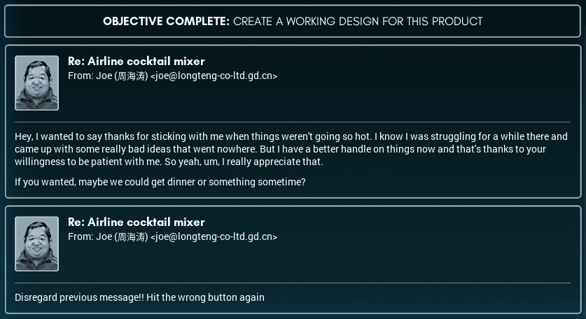 Honestly, I'm glad everything turned out OK with the guy. I mean, Joe could be an annoying person at times, and there�s no denying he had more harebrained schemes than an actual hare, but he's changed, and... well, everyone loves a happy ending. (Bonus: There's no way Joe was inviting Mr. Yonghong to dinner. Was this email intended for Lili?  ) )
|
|
#
?
Dec 13, 2018 11:23
|
|
|
So many cocktails, and none I'd actually drink. Curse my dislike of vodka. Also, I'm happy for Joe, but when he's inevitably shot down I hope he doesn't start returning to his old style. Hopefully he can use this personal growth towards nobler ends.
|
|
#
?
Dec 13, 2018 18:07
|
|

|
Crikey. I never got this far in Shenzhen, but it's clearly reaffirming my stance of it being at least the second hardest Zachtronics puzzler. Maybe even the hardest - a lot of my frustration with SpaceChem came from the slightly clunky interface. Also happy to see Joe doing well.
|
|
#
?
Dec 13, 2018 18:29
|
|

|
Grayshift posted:Crikey. I never got this far in Shenzhen, but it's clearly reaffirming my stance of it being at least the second hardest Zachtronics puzzler. Maybe even the hardest - a lot of my frustration with SpaceChem came from the slightly clunky interface. I've beaten the game and never had to do anything like the PGA or logic gate solutions here. It's a hard game, but drat, Quackles is making it look much harder than it is. Mega props for taking the time to do show all these solutions!
|
|
#
?
Dec 13, 2018 20:19
|
|

|
Y'know, it's been a while since I checked this blog, I wonder- washable e-ink clothing?  I love the concept, but I would not want to be anywhere near a team dedicated to finding that hardware solution. The easy part is the battery pack and scanner, that can go on a cable in the pocket and be detachable, but waterproofing the plug and the e-ink fabric is gonna be a Sisyphean ordeal. Worst case scenario, you need to utter the phrase "personal home dry cleaning," and heaven help the engineer in that meeting when the boss hears that. Especially if they think it's the best idea they've heard in weeks. And your manufacturing costs are going to be high enough that a consumer will want to wash them to get more use out of them, we can't go disposable like that recycled paper jumpsuit printer. You remember, the ones that fell apart in the rain? And that drink mixer is... Surprisingly feasible. Joe really has turned it around. I know three guys that would want one for home, one for the office, and one for their car. One of them doesn't own a self-driving, though, so I'm a little concerned about him.
|
|
#
?
Dec 14, 2018 01:26
|
|

|
GuavaMoment posted:I've beaten the game and never had to do anything like the PGA or logic gate solutions here. It's a hard game, but drat, Quackles is making it look much harder than it is. Mega props for taking the time to do show all these solutions! And now that I can look at my solutions I've got a straightforward �11 250 power solution. Two small MC chips and one big one. There's no need to do fancy logic work, but drat it's impressive nonetheless!
|
|
#
?
Dec 14, 2018 01:54
|
|
|
I was wondering why we never see some sort of even more complex version as like, a mixed drink vending machine, but then I realized you'd have no good way to comply with laws that put age restrictions on alcohol sales. I guess people who invent things need to think of the children. 
|
|
#
?
Dec 14, 2018 06:43
|
|
|
Want the cool verdion https://m.youtube.com/watch?v=1CqS3pRUbBI Or the practical version? https://www.hackster.io/sidlauskas/barbot-cocktail-mixing-robot-0318aa
|
|
#
?
Dec 14, 2018 07:03
|
|
|
Well, that liquid meter is lot more practical than solution with waveless liquid pump
|
|
#
?
Dec 14, 2018 18:34
|
|

|
Planes generate their own power so in that use case the only factors that matter are total cost and time needed to run a cycle. That said designing it with an eye towards reuse in future projects is a great idea. On a side note, why is the vermouth being used to ruin a perfectly good drink?
|
|
#
?
Dec 18, 2018 02:16
|
|

|
This post was made in error. It was meant to have the content of the next post in it.
Quackles fucked around with this message at 02:09 on Jan 19, 2019 |
|
#
?
Jan 4, 2019 08:22
|
|
|
Secret Project: Ra, Ra, Rasputin! So, those of you who have been following this blog for a while have noticed I've been mucking about in my spare time on something I call my 'secret project'. Well, guess what? My secret project is now here - and I'm ready to share it with you. Presenting: Ra, Ra, Rasputin. A fully multitracked version of Rasputin by Boney M, played on the finest (?) in electronic instruments. Set the video quality to 1080p HD for best results. https://www.youtube.com/watch?v=dZVrbpQoqg0&hd=1   As you've probably noticed, that is not the full size blueprint or wiring diagram - those are at the following links, 'cause they're just too darn big. Expect a 3500 x 2200 image at the end of each link. Full-Size Blueprint Full-Size Wiring Diagram Download a copy of this project (only works if you've modded your simulator) You can click on every other image in this post to get a full-sized version of it. This device uses 4 MC4000s, 35 MC4000Xs, 28 MC6000s, 7 200P-14s (small ROM chips), 15 200P-33s (big ROM chips), 16 FM/iXs (speakers), and 12 bridges (not counting the unused one in the corner), for a total cost of �411. The simulator doesn't track power usage if you don't have an active spec loaded into it, so I don't have any stats there. There are 32 time units per measure, and the piece is in 4/4 time, so a quarter note is 8 time units. Backstory and General Construction I got the idea for this project when I ran into a video on the web of Rasputin on a player organ. I was officially Inspired. After a fruitless attempt to get a MIDI file from the owner of the organ*, I found a MIDI file of the song elsewhere and began work. *The organ guy explained that player organs use their own unique scales. Any MIDI file he could provide would be useless. After a quick look at the MIDI file, I mentally broke the piece down into six parts: the bass line (BASS), main harmony guitar (HARMONY1), the sitar that replaces that guitar at one point as well as the piano chords during the chorus (HARMONY2), the vocal line (MELODY1), the strings (MELODY2), and drums (DRUMS). Each of these parts is marked out in its own color on the blueprint and wiring diagram - I'll explain each separately below. (There's also one extra part in the finished device: a few 'MAIN' conductor MCs that keep everything running together, and are responsible for cueing everything else.) For each part of the piece, I followed roughly the same procedure: [1] Open the MIDI file in a music editor, and see if there were any patterns in the notes. (I decided not to include the B section of the song or the chorus after it - if the player organ guy could get away without it, I could too.) [2] Make an encoding scheme that would store this particular part efficiently. (Most of the parts use different encoding schemes.) [3] Put the encoded part in a ROM chip - or two or three. (Usually three.) [4] Make a design to play the part when cued by the conductor MC. [5] Test the design to see if it worked. [6] Fix any bugs that cropped up. [7] Repeat [5] and [6] a few times until everything worked. And then I'd be one step closer to a finished device. Challenges, Big and Small There were two big challenges in building this. The first was finding enough space. I had to install an unofficial mod to my simulator to get it to recognize boards this big at all - and since the project's using almost all the space, I can only conclude the 'software update' was worth it. The second big challenge, more seriously, was lag. I suspect the reason the simulator never had the native capability for large boards is because once I had about 4 parts of the song in (covering 2/3 of the board or so), the playback started to lag and slow down below the song's tempo. I solved this by halving every unit of duration in the song's timing, effectively doubling the speed! From there, I was able to get the right tempo by adjusting the 'simulation speed' slider. Even so, the simulator can still lag a tiny bit during playback - more if you're running other applications in the background. There were a few little challenges, too. No offense, Mountleaf Sound Concepts - but your instruments suck! They sound like a computer with a cold playing a kazoo. I did the best I could, though, picking goodish-sounding instruments (and sometimes mixing instrument sounds together). List of All Score Sections Every so often, in the rest of this post, you�ll see me refer to parts of the piece by a section number. I split the piece into internal sections, and this list explains what each refers to. The list includes the relevant vocals from the song�s first verse, in case you�re following along with the original Boney M recording. 0: Intro chords 1: Rising opening guitar melody (repeat goes from here) 2: Sitar melody (first half) 3: Sitar melody (second half) 4: Vocals (�There lived a certain man / in Russia long ago��) 5: Vocals (�He was big and strong / in his eyes a flaming glow.�) 6: Vocals (�He could preach the Bible like a preacher� / �But he also was the kind of teacher�) 7: Vocals (�Full of ecstasy and fire,�) 8: Vocals (�Women would desire.�) 9: Chorus (�Ra, Ra, Rasputin! Lover of the Russian queen!�) 10: Chorus (�There was a cat that really was gone!�) 11/12: Last measure - piece repeats (12) or ends (11) after this. Part 0 - The Conductor   This is the heart of the project, consisting of the main conductor MC (which I nicknamed 'Junko' after a character in another famous Let's Play), two broadcaster MCs, and a memory chip that holds the 'piano roll'. Every 64 time units (2 measures), Junko reads off a new value from the piano roll and sends it to the broadcasters, which cue the various other parts of the project. Complications There's a bit of a wrinkle once the piano roll hits the cell with the value `11`. This is the last section of the piece, and is only one measure long. The first time this happens, Junko will send '12' (not '11') to the broadcasters, then rewind the piano roll to repeat most of the piece. The wait time on this section is adjusted from two measures to one so there's no gap before the repeat. (As an aside, the repeat made my job a lot harder. Instead of writing scripts for the rest of the MCs that could do only-use-once tricks, I had to make everything able to run at least twice.) Once a value reaches the broadcasters, they copy it to the receiver chips of the rest of the project (as shown in the wiring diagram). There's a few wrinkles with this process, though. First, note the negative numbers in the piano roll: they indicate a variation from the original section with the matching positive number (so '-5' is 'variation of section 5'). Not all parts of the player read variants, so the broadcasters remove it before sending. The Bass, Vocals (MELODY1), and Drums parts don't use variant data, while the rest do. It's also worth noting that the Melody Guitar (HARMONY1) part gets sent its cue twice: once with the variant number and once without. HARMONY1 is the most complicated part of the entire project, so I'm not surprised, on retrospect, that I did custom stuff cueing it. Finally, fun fact: There�s code in the conductor to stop the project after the repeat plays through, but it never gets used! The reason for this is that the device actually stops due to the bass player part blocking after the entire score has been played. This is at least partially because of a dubious design decision while I was creating that part� Total cost for this part: 2x MC4000X (�6) + 1x MC6000 (�5) + 1x 200P-33 (�4) = �15. Now, on to the inner workings of each part of the device. Part 1 - The Bass Line (BASS)   The bass line was the first part I constructed. On the face of it, it's fairly simple - the bass line only plays one note at a time, that note is often repeated, and it stays within a range of a few octaves or so. The only real wrinkle with the part is that I compressed the notes to fit into two large ROM chips, so a large amount of the BASS part's footprint is devoted to decoding the compressed data. Here's how it works. Bass Note Encoding Each cell in the two big ROM chips on the left is a sequence of notes. The leftmost digit of the cell keys for the note pattern, and the other two digits set the pitch of the note (this number is passed directly to the speaker). Different first digits key for different note patterns: 1-5 = 1-5 repeated eighth notes, all of the same pitch:  6 = single quarter note (♩) 7 = two eighth notes (♫), the second an octave higher than the first:  8 = four eighth notes (♫♪♪). The third eighth note is a fourth lower than the other three:  If a cell has a negative number, the device part adds an eighth rest (  ) before reading the next cell; if the cell is a 0, the device part considers this section to be all done, and waits to be cued by the conductor again (well, sort of - see below). ) before reading the next cell; if the cell is a 0, the device part considers this section to be all done, and waits to be cued by the conductor again (well, sort of - see below).How It All Works 1. Receiver When a cue comes in from the conductor, the Receiver looks up the associated cell in the Score Address Table, and sends that value (which codes for which score chip to use, and where in the chip to start playing the score) to the Syncer. If the value it read from the table is a -1, it does nothing instead. 2. Syncer The Syncer takes the value from the Receiver and splits it into two parts. The leftmost digit of the value indicates which Score ROM chip to use: #1 (the upper one) or #2 (the lower one). The other two digits of the value are the address to set the ROM chip to. The Syncer sets the correct ROM chip to the correct address, then passes the number of which chip to use on to the Reader. 3. Reader The Reader is one of the most complicated MCs in this part, as it is at the center of the part's 'push-pull' timing architecture. It receives input as follows: A. From the Syncer, the Reader gets notified over XBus (on its x2 line) when a new section is starting. Effectively, cues are 'pushed' out from the conductor end, and find their way to activate the Reader. B. The Reader is also notified over a different XBus line (x3) when the Player and Decoders, down the chain, are ready for the next note. The Player and Decoders will always send a 'next note' request after the current pattern has finished playing - they don't know what the conductor is doing. They just know that the Reader will always provide new notes on request. Effectively, 'next note' cues are 'pulled' down from the Player end. This puts the Reader in an impossible position. For each section, it has to receive the wakeup message from the conductor, deliver all the notes to the Player (cued by the Player as necessary), then go back to sleep so that it can receive the message from the conductor again. It can't ignore the conductor's message while it's waiting for a 'next note' message, because then the Syncer will be trying to pass the message on and it'll block. It also can't not respond to a 'next note' request when waiting for the conductor's message, because the Decoders will be reading, and it'll also block. Before you ask, a read/write block in the simulator's sandbox mode is just like a block in the production mode, except it doesn't pop an error message to show you where the block is - you have to track it down yourself. TODO_EMOTE What makes this all work is the '0' entries in the Score ROM chips. They signal the Reader that the section is finished, a conductor message will be coming in in this time unit, and that it's safe to wait for it. With this, the bass part hums along like a finely honed watch. If you're wondering why I made it this way, the answer is simple: variable length note patterns. As mentioned above, note patterns for the bass part can be anywhere from 1 to 5 eighth notes long. There's not enough space in the Reader MC to tell it how long to wait before sending the next cell of the ROM chip, so instead I used this message-driven model; the Player can ask when it's ready for the next pattern. It's fiddly, but it works. 4.-7. Decoders #1-4 Now that we're upstream from the Reader and firmly in the land of 'pull' timing, the design becomes a lot simpler. Each of the Decoders is responsible for decompressing the single ROM cell read and passed on by the Reader, and turning it into a sequence of 'play this note' values to send to the Player. Each Decoder has the following general pattern: A. Wait for the timing pulse from upstream (the Player). Pass it on to the next Decoder or the Reader, and wait for a response. B. When getting a response (the note pattern), transform it in some way. The nature of the transformation varies by Decoder. C. Send the transformed notes back upstream towards the Player, where they'll pass through the next Decoder. More specifically, here's what each Decoder does to the note pattern on their way to the player: 4. Decoder #1 If the note pattern is a negative number (signifying an eighth rest after the note pattern is done), this Decoder multiplies the pattern by -1 to turn it into a positive number, and passes it on. It then intercepts the next "next note" pulse to reach it, and replies with 100, code for a rest (00) of 1 eighth note in length. If the note pattern is a positive number, the Decoder passes it on unaltered. 5. Decoder #2 If the note pattern starts with a 7, indicating two eighth notes in an octave, this Decoder replaces the '7' with a '1' to make it look like a regular single eighth-note play request, and passes the altered pattern on. It then adds 12 (one octave) to the pitch of the eighth note it sent, intercepts the next "next note" pulse, and replies with the pitch-shifted eighth note. If the note pattern starts with something else, the Decoder passes it on unaltered. 6. Decoder #3 If the note pattern starts with an 8, indicating the pattern of 4 eighth notes with the lower third note, this Decoder replaces an '8' with a '2' to play the first two eighth notes of the pattern, passing the altered pattern on. It then intercepts the next two "next note" pulses, sending the pitch-shifted lower note (subtracting 5 from the pitch value), then the restored fourth note, up to the Player as single eighth notes. If the note pattern starts with something else, the Decoder passes it on unaltered. 7. Decoder #4 This Decoder transforms every note pattern that passes through it. It splits the pattern into two parts: the first digit (pattern code), and the last two digits (the pitch), and sends them to the Player as two separate values. This Decoder doesn't intercept "next note" pulses. Once the dust has settled, the Decoders have turned the note pattern into a sequence of paired values, ready for the Player at last. 8. Player This MC actually sends the commands to the speaker to play the notes. It starts by sending a "next note" pulse in the direction of the Reader, then storing the pattern code it receives in return into its acc, and the pitch into its dat. It then sends the note to the speaker. If the pattern code is a '6' (quarter note), it waits 8 time units and clears acc; otherwise, it waits 4 and subtracts 1 from acc. Once the note is done, the player MC stops the note by sending a value of to the 'instrument' pin of the speaker, which stops any notes in progress. If there's any value still left in acc, it sends the note to the speaker and repeats as necessary (this is how the repeated eighth notes are played); otherwise, the Player's script repeats, it sends out another "next note" pulse, and the cycle begins all over again. The speaker for this part uses instrument #4, "Rubber Bass". Total cost for this part: 3x MC4000X (�9) + 5x MC6000 (�25) + 1x 200P-14 (�2) + 2x 200P-33 (�8) + 1x FM/iX (�5) = �49. Part 2 - Main Harmony Guitar (HARMONY1)   The main harmony guitar was the second part I constructed, the most complicated, and one of the most if not the most difficult part of the whole endeavor. Like the bass part, it stores compressed patterns of notes in its �Score' ROM chips, and also uses a push-pull timing architecture because of this (confused? see the explanation for the bass part's "Reader" chip, above). Unlike the bass part, this part plays 3-note chords and not single notes - necessitating extra data storage and decoding. Harmony Guitar Chord Encoding Each pattern of harmony guitar notes takes up not one, but two cells in the Score ROM chip. The first cell lists the chord to produce (each digit of the chord cell says how many semitones to put the next note of the chord ahead of the previous one). The first digit of the second cell lists the timing pattern. The last two digits of the second cell list the pitch of the bottom note of the chord. Different chord patterns produce different chords: 0 = no chord; all speakers will play the same note 32 = minor 3rd with added 4th note (technically a kind of 7th chord) 34 = minor chord 35 = major chord, first inversion* 43 = major chord 45 = minor chord, first inversion 53 = minor chord, second inversion 54 = major chord, second inversion 75 = octave with a 5th in the middle 99 = special cue - two minor chords, going from a first to a second inversion (45 to 53) *For those who aren't musical: An 'inversion' is when you take the lowest note of a chord and put it on top by raising it an octave. The new chord sounds pretty similar, only higher-pitched. The pitch called for in the score ROM chips is always the note that's on the bottom after the inversion has happened, if one is called for. On top of that, different first digits in the second cell key for different timing patterns: 0 =  1 =  2 =  3 =  4 =  5 =  (rest one measure) (rest one measure)6 = 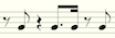 7 = 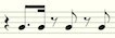 8 =  9 =  (Timing patterns from 0-4 last for half a measure. Patterns from 5-9 last for a whole measure.) Finally, if the second cell is negative, it indicates the end of a section, which will cause the Data Splitter to wait for a cue from the conductor before continuing. How It All Works 1. Receiver Like with the bass Receiver chip, the harmony guitar Receiver reads the section number from the broadcaster, pulls the matching cell from the attached Score Address Table, and sends it on. There is one extra wrinkle, though - this Receiver gets the section number twice. The first value received will be a negative number if the section to be used is a variant section, and positive otherwise. The second value is always positive, and this is what gets sent to the Score Address Table's address line. Once the Receiver has pulled the value from the Score Address Table (which will indicate where and from which ROM chip to start reading the score section), there's one extra wrinkle: if the section is supposed to be a variant, the MC adds 8 to it. This will make the Reader read from the variant section data instead of the normal section data - the variant data is stored right after the normal data. Both of the sections that have variants (#5 and #10, which are the second half of the initial vocals section and the second half of the chorus) are exactly 8 values long when stored, so 'add 8' works in both cases. Once the Receiver has the address, it sends it off to the Address Separator twice: the first time with the first digit (indicating the chip to send to) intact, the second time with it removed. Both values are used in different places down the line. 2. Address Separator The next MC in the line, the Address Separator, receives the address with the first digit, removes everything but that first digit, and sends it along its output line (x1) to the Syncer just below it. However, it also sends this same digit along its simple I/O line, p0 (!) to the reader, before sending the last two digits (received from its input) to the Syncer again. There's a specific reason for all of this. Put simply, the bass part had two Score ROM chips to choose from, so the bass Syncer (to set the ROM chips' addresses) and the bass Reader (to read from the ROM chips) could both have one XBus line for input, another XBus line for output, and then the remaining two XBus lines would each go to a ROM chip. The harmony guitar uses the same syncer-reader design pattern, but there are three score chips to read from / set the address of instead of two. So, the harmony guitar Syncer and Reader can only have a single XBus line for communicating with other chips. This means that the Reader needs a way to know which chip to read from, without using an XBus line (as the XBus line is used to output data)*. So, once the Address Separator sets its simple I/O line, that value sticks and tells the Reader (on the other end of the wire) which chip to read from until the Address Separator changes it. *OK, so you could have it so that when the Reader is pinged to read the next value, the ping tells it which chip to look at. This way seemed simpler at the time, though. The output to the Syncer has a side effect as well. The Syncer doesn't have space for an output line (as its other XBus lines are connected to the Score ROM chips), so the pulse that notifies the Syncer also wakes up the Data Splitter (see 5. Data Splitter Part 1, below), getting it ready for a pulse from the Primary Timing Engine. Effectively, the Address Separator's output acts to bridge the two areas of the part: the MCs leading to the Syncer, and the MCs reading from the ROM chips and processing the data (which aren't otherwise directly connected to one another). 3. Syncer Once the Syncer receives input with a ROM chip number and address, it sets the correct ROM chip's address pointer to the address it received. That's all it does. 4. Primary Timing Engine (Part 1) The Primary Timing Engine MC, sends out a pulse leftwards to the reader (by way of the data splitter) to cue the reader to read the next measure (or half-measure). (It sends this pulse at the start of each new measure or half-measure, depending on what timing pattern was last read.) 5. Data Splitter (Part 1) When the Data Splitter (between the Reader and Primary Timing Engine) gets the timing pulse from the Primary Timing Engine, it immediately passes it on to the Reader on its left. However, there's one circumstance where this 'pass' is a bit delayed. If the harmony guitar part is about to start a new section (that is, at the start of the playback, or after the Data Splitter gets a negative value from the Reader), the Splitter will hold off on processing the timing pulse until it gets a cue from the Address Separator instead (on the Splitter's x0). This is to ensure the Syncer has had time to properly set the address of the ROM chip the Reader is supposed to read from. 6. Reader When the Reader is cued by a timing pulse on its I/O line (x3), it checks its p0 (set by the Address Separator) to see which ROM chip it should be reading from. Then, it reads two values from the chosen ROM chip, and sends them out on x3 to the Data Splitter. 7. Data Splitter (Part 2) The fun starts when the Data Splitter gets a pair of values in from the Reader. The Data Splitter, as its name might suggest, sends these values off in different directions. The first value, which stores the chord information, gets sent to the Chord Engine right below it (see 8. Chord Engine, next). The second value (storing timing and pitch) gets sent along to the Primary Timing engine - twice. The first time, the entire value is sent - this will be used for its pitch value. The second time, only the leftmost digit of the value is (and it's made positive if it's a negative number). This digit will be processed as timing information. If the second value the Splitter received was a negative number, signaling the end of a section, the Data Splitter will wait for a pulse from the Address Separator before it starts listening to the Primary Timing Engine again. 8. Chord Engine Once the paired values of the next notes to play leave the Data Splitter, they're sent in two separate directions to be processed separately. The Chord Engine, just below the Data Splitter, gets the chord value. For the most part, the Chord Engine's job is to pass the chord it receives on to the Player MC to its left. However, if the Chord Engine receives the special code '99', it will instead output '45', wait for 12 time units (the length of three 16th notes), and change its output value to '53' (these two values code for two different minor chords). It's also worth noting that the Chord Engine outputs its data over simple I/O, not XBus. This is so that the Player can use one chord value for an entire pattern of chords, until a change is called for. 9. Primary Timing Engine (Part 2) The Data Splitter sends the information on the pitch and timing of the chords back to the Primary Timing Engine, which acts as a decoder. The Primary Timing Engine splits the information and sends it in two directions again! The pitch value gets copied and sent out on the Primary Timing Engine�s p1 (simple I/O line), which will end up at the Timing Collector below and slightly to the left of it. The timing value (a single digit), however, triggers one of three possible reactions depending on what the number is. If the timing value is between 0 and 7, the Primary Timing Engine will send the ID number out on its x3, waking up the Note Length Address Lookup MC (which will eventually notify the Secondary Timing Engine for Normal Patterns MC). These MCs will then handle generating the correct timing pattern from storage. For more about the normal timing patterns, see 10. Note Length Address Lookup, 11. Note Timing Cache, and 12. Secondary Timing Engine for Normal Patterns, all below. If the timing value is an 8, it refers to this pattern: In this case, the Primary Timing Engine will send a ping on its x1, to wake up the Secondary Timing Engine MC for Pattern #8 just below it. This MC handles that pattern in software. For more information about Timing Pattern #8, see 13. Secondary Timing Engine for Pattern #8, below. Similarly, if the timing value is a 9, it refers to this pattern: In this case, the Primary Timing Engine sends a ping on its x2, which wakes up both Secondary Timing Engine for Pattern #9 MCs. Yes, that�s right - one timing pattern has two whole MCs devoted to playing it back! For more information about Timing Pattern #9, see 14-15. Secondary Timing Engine for Pattern #9, Parts 1 and 2, below. 10. Note Length Address Lookup Most timing patterns will result in the Primary Timing Engine sending the ID number of the pattern to this MC, near the bottom right of the harmony guitar area. The Note Length Address Lookup MC sends the ID it receives to the address line of the attached small ROM chip on its right. That ROM chip - the Note Length Address Table - is an index to the Note Length Data table in the other small ROM chip to the far left. Once the Note Length Address Lookup MC has the address of the starting location in the Note Length Data table to use, it sends it out to the Note Timing Cache, by way of the Secondary Timing Engine. It will also send a reminder ping to the Note Timing Cache after half a measure if this pattern is supposed to be a full-measure pattern, to keep things going. 11. Note Timing Cache The Note Timing Cache gets the address of where it�s supposed to start reading from the Note Length Data table ROM chip just to its left. It then reads values from the Note Length Data table for as long as the Secondary Timing Engine for Normal Patterns keeps asking for more data. The Note Length data table represents the following sequence of notes: 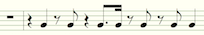 The Secondary Timing Engine (cued by the Note Length Address Lookup MC) will ask for either 2 or 4 quarter notes� worth of time from this sequence, starting wherever in the sequence the Note Length Address Lookup MC says it should start. Each of the timing patterns from 0-7 are subsequences of this sequence. The Secondary Timing Engine reads each read value twice, so the Timing Cache outputs the value twice - making the second copy of the value positive if it�s originally a negative value (negative values indicate rests in the Note Length Data chip). 12. Secondary Timing Engine for Normal Patterns This MC passes messages between the Note Length Address Lookup MC and the Note Timing Cache. It reads the resulting data the Timing Cache outputs, passing it on to the Timing Collector (see 16., Timing Collector, below). It also keeps track of the sum of the absolute value of the note timing values it�s received - if the sum adds up to 16, the Secondary Timing Engine will stop, as it�s read half a measure worth of time. (If the timing pattern it�s receiving is supposed to be a full-measure pattern, the Note Length Address Lookup MC will ping the Secondary Timing Engine to get it to keep going and receive the second half of the measure from the Timing Cache.) 13. Secondary Timing Engine for Pattern #8 This MC, sandwiched vertically between the normal Secondary Timing Engine and the Primary Timing Engine, is responsible for outputting Timing Pattern #8: This pattern is used just after the intro section of the piece. One of the reasons this pattern is being output manually is that the second note is actually one semitone lower than the first. When the time comes to do the changeover, the Secondary Timing Engine for #8 takes the note pitch value from p0, adds 39 to it, and puts it back out on p0, overwriting the previous value. This works for two reasons: First off, if two MCs write different values to a simple I/O wire, the highest value wins. Second - the entire part is set up deliberately to allow this override. The pitch values of cells in the Score ROM chips that use the 8 and 9 timing pattern codes have had 40 pre-subtracted from them. The harmony guitar Player knows that if a note has a pitch of below 40, it should have 40 added to the pitch before playing it. When this Secondary Timing Engine adds 39 to the pitch value, this is the same as adding 40 by itself� and then subtracting 1! Effectively, this Secondary Timing Engine is overriding the pitch put out by the Primary Timing Engine� with simple I/O lines - ensuring that it has the highest simple I/O value, but it�s read as a lower note than what came before it. Aside from this wrinkle, the code for this Secondary Timing Engine is pretty simple, sending the pattern of notes and rests shown above to the Timing Collector (see #16 below.) 14-15. Secondary Timing Engine for Pattern #9 (Parts 1 and 2) Timing Pattern #9, used only in the intro to the piece, presents a similar challenge to timing pattern #8: it has notes in a nonstandard rhythmic pattern, and a step down in the middle: However, this time, there are enough notes that the pattern is split into two MCs, both on the right side. The Part 1 MC concerns itself solely with the pitch of the notes. It uses the same 'add 39' trick that the Secondary Timing Engine for Pattern #8 does (see just above) to override the pitch set by the Primary Timing Engine in the middle of the measure. It sends the updated pitches, on its p0 line, to the Timing Collector. (There�s one extra extra wrinkle: the second time this MC is called on to do this, the extra �sub 1� instruction kicks in, lowering the pitch by two semitones instead of one. This is to deal with the intro�s chord progression harmoniously.) The Part 2 MC focuses on the actual notes and rests used in the timing pattern, and sends those timing values to the Timing Collector in the correct rhythm. 16. Timing Collector The Timing Collector, in the center bottom of the harmony guitar part, is where just about everything comes together. This MC takes input from all three Secondary Timing Engines and the Primary Timing Engine. The Timing Collector�s actual job is simple: when it receives an XBus pulse from a Secondary Timing Engine (on its x1 line), it checks if the pulse is positive (a note) or negative (a rest). If it�s positive, it sends the pitch value (received from one of the Timing Engines on its p1) to the Player Coordinator, to its left, followed by the pulse as a timing value for how long the next note should be. If it�s negative, the Collector sends -999 in place of the pitch (to indicate �silence�), turns the timing value into a positive number, and sends it along. 17. Player Coordinator The Player Coordinator exists for one simple reason: the harmony guitar part has to play chords. Instead of one Player MC to deal with, there�s three - one for each note of the chord. When woken up by the Timing Collector, the Player Coordinator handles this by taking the chord value from the Chord Engine, and sending it to both the �Mid Note� and �Top Note� Players (the Base Note Player doesn�t use it). From there, it sends the pitch value (from the Timing Collector) to the �Base Note� and �Mid Note� players (the �Mid Note� player will pass it on to the �Top Note� player - this saves a line of code), and sends the timing value of the note to all three. Then, it waits for the next note from the Timing Collector. (The �add 40� line is so that special timing patterns can work properly. See 13. Secondary Timing Engine for Pattern #8, above, for more info.) 18-20. Players (Base, Mid, and Top Note) The Player MCs are mostly the same, but with some slight differences. In order to replicate the three notes of a chord, the Players all take the same pitch value and play it for the same amount of time - but the Mid Note and High Note Players raise their pitch by one of the digits of the chord value they received first. Here�s how each player works, step by step: A. The Mid Note and High Note Players both get the chord value from the Player Coordinator. They each store one of the two digits of the value in their acc. B. The Base Note and Mid Note Players both get the pitch value from the Player Coordinator. The Base Note Player doesn�t need to do anything with it, so it just stores it in its acc. Meanwhile, the Mid Note Player adds the pitch value to the stored digit of the chord value, raising the note by several steps. C. The Mid Note Player passes its boosted pitch value to the High Note Player, which boosts it again by adding it to its own stored chord value digit. All three Players now have pitch values corresponding to the bottom, middle, and top nodes of the chord. D. All three Players pass their pitch value to their attached speaker. (If the note is less than 0, indicating a rest, this step gets skipped.) E. All three Players receive the timing value from the Player Coordinator, and wait that long before stopping the note and listening for the next data. The cycle begins again. The speakers for this part use instrument #1, �Plucktar�. Total cost for this part: 3x MC4000 (�9) + 7x MC4000X (�21) + 8x MC6000 (�40) + 4x 200P-14 (�8) + 2x 200P-33 (�8) + 3x FM/iX (�15) = �101.
|
|
#
?
Jan 19, 2019 01:57
|
|
|
Part 3 - Harmony Sitar and Chorus Piano (HARMONY2)  Most of the parts past this point are easier to understand and generally all-round simpler. This part is one example - it plays during where the sitar melody was in the original song, as well as doubling up on chords during the chorus. It uses an encoding scheme, like the harmony guitar chords, where each note is stored in 2 ROM chip cells. However, the Score ROM chips here only store single notes, instead of timed patterns of them. This simplifies the part�s construction immensely. Harmony Sitar/Piano Chord Encoding Like HARMONY1, this part uses 2 score cells per note. The encoding scheme is a bit different in this part. The first cell details everything about a single chord - both the pitch of its base note and the chord to use. The leftmost digit of the number in the cell tells what chord to use. The other two digits of the first cell tell the pitch of the bottom note of the chord. If the first cell is entirely 0, however, this indicates a rest instead of a note. The second cell lists the length of time the chord lasts. A �2� is a sixteenth note (2 time units), a �4� is an eighth note (4 time units), an �8� is a quarter note (8 time units), and so on. (The table of chords is listed below, under 6. Chord Calculator). There are two single-cell control codes, as well: �-111� indicates that there�s no more room on the score chip, and the reader should switch to the next one. �-999� indicates the end of a section. How it All Works 1. Receiver Most Receiver MCs have a big job: notifying the relevant MCs when it�s their turn. However, this part of the device only plays during two sections of the piece, so this Receiver's design is a little different. This Receiver will notify the Verse and Chorus Readers at the start of the second �1� section (right before the sitar melody kicks in) - and it�ll reset the address pointer of the top left Score ROM chip at the end of the chorus (this is so that the Verse Reader can work properly once the song repeats). Aside from the above duties, this Receiver throws out all other messages from the conductor. Life is relaxed in HARMONY2 town! 2. Verse Reader The Verse Reader gets notified by the Receiver when it�s time to start playing. It�ll immediately start reading pairs of values from the attached ROM chip (Score, Sections 2-3; the left ROM chip in the top row), and sending them to the Collector, directly below. (This part of the device uses a �push� timing architecture only - signals only flow from the conductor, to the Readers, to the Players, to the speakers - never in the other direction. The Verse Reader will use the timing values it reads to know how long to wait before reading the next pair of values.) As it turns out, the score for the sitar section is too large for a single ROM chip to contain it. So, when the Verse Reader reads the control code �-111�, it pings the Continuation Reader (see 4. Continuation Reader, below), which carries on where the Verse Reader leaves off. The Verse Reader will wait for 52 time units (1 and 5/8 measures) for the Continuation Reader to finish; then, it repeats the sitar part once from the beginning. 3. Chorus Reader The Chorus Reader gets notified by the Receiver from the same pulse that notifies the Verse Reader. There�s one major difference: the Chorus Reader then waits 832 time units (26 measures), and then starts reading. Effectively, the starting wait acts as a timer to ensure the chorus chords flow at just the right time. The Chorus Reader reads from the �Score, Sections 9-10� ROM chip, in the top center. Like the Verse Reader, the Chorus Reader sends the data it reads to the Collector MC. The score for the chorus section is also too large for a single ROM chip; on reading the control code �-111�, the Chorus Reader pings the Continuation Reader to pick up where it left off. As the chorus repeats once, the Chorus Reader will wait 48 time units (1 and 1/2 measures) for the Continuation Reader, then read its section of the Score from the top again. 4. Continuation Reader The Continuation Reader is responsible for reading the back half of the score segments for both the sitar melody and the chords used for the chorus. Both back parts are stored in the Score chip attached to the Reader, labeled �Score (Continuation)�. The Continuation Reader knows where to start reading because: when one of the other Readers pings it, the ping contains the address of the cell in the ROM chip to start reading from. The Verse Reader pings with cell 0; the Chorus Reader pings with cell 20. This way, both segment parts can coexist on the same ROM chip. Like all other Readers for this part, the Continuation Reader sends the data it reads to the Collector. If it reads a �-999�, it considers its job done, and waits to be pinged again. 5. Collector The Collector receives the two-cell score data from the Readers, and sends it to the Chord Calculator just below. If the data it receives has a first-cell value of �0� (signifying a rest), it throws it out and waits for the next data instead (no need to wake up the Players to play nothing). When the Collector does send the data to the Chord Calculator, it splits it into two: the pitch data gets sent over its p0, while the chord and timing data get sent over XBus. This is so that the Chord Calculator can act as a pass-through for the pitch data. 6. Chord Calculator The Chord Calculator�s job is to take the first digit from the received chord value, then calculate the actual chord number. Digits from 0-2 indicate a two-note chord, and digits from 3-5 indicate a three-note chord. 0 = 03 (minor third) 1 = 04 (major third) 2 = 05 (fourth) 3 = 43 (major chord) 4 = 54 (major chord, second inversion) 5 = 75 (octave with a 5th in the middle) The �sitar� verse section only uses two-note chords, while the chorus section uses almost entirely 3-note chords. Once the Calculator has the final chord value, it outputs it and the timing value (copied from the Collector) over its x3 line, to the Player Coordinator. The Chord Calculator also takes the pitch value from its p0, and copies it over to its p1. This is only because I wasn�t able to run a simple I/O line from the Collector to the Player Coordinator. 7. Player Coordinator Like the harmony guitar part�s Player Coordinator, this Player Coordinator is here to deal with the issue that there are three separate Player MCs - one for each note of the chords this part plays. This Player Coordinator�s script is almost the same as the harmony guitar part�s, too� it sends the chord value from the Chord Calculator to the Mid Note and Top Note players, the pitch value (received on its p0) to the Bass Note and Mid Note Players, and the timing value to all three. 8-10. Players (Base, Mid, and Top Note) The Player MCs use the same pattern as the Players for the harmony guitar chords part. The Base Note Player plays the pitch value for the set amount of time. The Mid Note Player takes the pitch value, adds the left digit of the two-digit chord value, and plays that. It also sends its modified pitch value to the Top Note Player, which adds the right digit of the two-digit chord value - and then plays that. All three Players wait for the period given by the timing value, then stop their note. There are a few quirks of these Players that don�t apply to the harmony guitar versions, though. First off, all three players still play if it�s a two-note chord. Due to the way the Chord Calculator is set up, the Base and Mid Note players will both play the lower note of the chord, and the Top Note Player will play the upper note. On top of that, there�s also a slight design flaw. These Players check if the received pitch value is greater than 0, and will only play if that�s the case (so that the part is silence if the score indicates a rest). However, due to a line of code in the Collector that checks for a rest earlier (and only sends data Playerward if it�s an actual note), these tests will always pass - they�re redundant! Yeah. I never got around to fixing it. I could save a few lines of code this way, but the device is done and that�s what matters. The speakers for this part use instrument #2, �Tines�. Total cost for this part: 1x MC4000 (�3) + 5x MC4000X (�15) + 4x MC6000 (�20) + 3x 200P-33 (�12) + 3x FM/iX (�15) = �65. Part 4 - Melody Vocals (MELODY1)   The main melody line parts are a lot more straightforward than the previous sections of the piece. Each note is stored in one cell of a ROM chip. There�s no chords to deal with. The Readers send directly to the Players. All in all, it�s a lot less of a headache! Vocals Note Encoding Each note in the vocals is stored in one ROM chip cell. For positive numbers (indicating notes), the leftmost digit of the cell indicates the node length (1 = eighth note, 2 = quarter note, 3 = dotted quarter note [1.5x a normal quarter note], 6 = dotted half note [1.5x time a normal half note]), and the other two digits are the pitch of the note. A negative number indicates a rest for that many time units, while a 0 marks the end of a section (which will cause the active Reader to stop reading). How it All Works 1. Receiver and Address Getter The Receiver�s job is to listen for cues from the conductor, as always - and then, tell the rest of the part what ROM chips to read from. However, while this Receiver uses a score address table, it�s not in a separate memory chip. Instead, this part�s Receiver uses free space at the end of the Score ROM chip for Section 4 (just up and to the right of it) as its address table instead! The Receiver will get the right address (as long as the section cued is #6 or higher), and send it along to the Routers (see 2-3. Routers, below). This Receiver also has one hardcoded address in it, as well - this is because the Reader that reads from the Section 4 Score ROM chip has to start a few beats before the conductor cues in section 4. This is so that it can do a few notes that are part of a pick-up bar to section 4. As such, the Receiver waits until the second cue for section 3, then sends the hardcoded address �200� on to Router #1 instead. 2-3. Routers #1 and #2 The address the Receiver digs up gets sent to Router #1 first. If it�s a �200�, signaling that Reader #1 is due for its cue, Router #1 will wait 60 time units (1 7/8 measures), then cue Reader #1. It�ll cue Reader #1 again 4 more measures after that, because its section repeats, but the cue from the Router does not. If the address the Receiver sends over is not a �200�, Router #1 will pass it to Router #2. An address more than 100 will be sent to Reader #3 after its first digit is removed, while an address less than 100 will be sent to Reader #2. 4-6. Readers #1-#3 All three Readers have the exact same code (except for different pin numbers to accommodate different wiring schemes). Each Reader gets input from one of the two Routers, and when triggered, they move to the indicated starting address of their attached Score ROM chip, reading values from there until they hit a �0�. Like the harmony sitar and chorus chord Readers, these Readers keep track of the time of each note by themselves. The notes each Reader reads are sent to the top Primary Player on the left. Each note gets turned into two sent values: the first is unchanged from the read value, and is used for the pitch. The second is the timing value (leftmost digit) extracted from the read value, which is used for the timing. 7-9. Players (Primary and Secondary) Unlike the harmony guitar part or the harmony sitar/chorus part, this part of the device does not need to do chords. However, there�s three Players anyway. This is so that the melody part doesn�t get drowned out by the harmony parts - both have the same number of speakers at their disposal. Each Player will send the received note and timing information to the next Player in line, if there is one, before cueing their attached speaker for the amount of time the note runs. The speakers for this part use instruments #0, �Harpsiclav�, and #6, �Reso Strings�. The difference between a Primary and Secondary player is that the Primary Players use Harpsiclav, and the Secondary Player uses Reso Strings. This makes a nice blended sound. Total cost for this part: 5x MC4000X (�15) + 4x MC6000 (�20) + 3x 200P-33 (�12) + 3x FM/iX (�15) = �62. Part 5 - Melody Strings (MELODY2)   The melody strings part is very similar to the melody vocals part. It is slightly more complex, however - the biggest complication comes with the fact that the melody strings are playing more frequently (often for short �stings�), so the part needs more �Score� ROM chips to store all the data. This part has the most Score ROM chips of any part of the device, at 4 distinct chips! Strings Note Encoding Like the vocals, each note in the strings is stored in one ROM chip cell. Positive numbers (other than 999) indicate notes. The leftmost digit of a cell with a note value indicates the note length (1 = sixteenth note, 2 = eighth note, 4 = quarter note, 8 = half note), while the other two digits indicate the pitch of the note. Negative numbers indicate to rest for that many time units (32 time units to a full measure). A �999� marks the end of a section - once a Reader reads this value, it will stop. How it All Works 1. Receiver The Receiver�s job is simple: it gets the cues from the conductor, and passes them on to the Address Syncer, just to its right. However, there is one quirk: if the Receiver gets a cue for section 9 (the start of the chorus), the Receiver will discard all further cues until the chorus is over. This is because the chorus�s timing is handled separately by the Special Pattern Handling MC, down the line (see 5. Special Pattern Handling, below). 2. Address Syncer The Address Syncer gets the most recent cue from the Receiver. If it�s a �9�, signaling the start of the chorus, it immediately pings the Special Pattern Handling MC. Otherwise, it uses the cue to set the address pointer of the Score Address Table ROM chip, which is tucked beneath the ROM chip for the Score, section 5A. Fun fact: if the cue the Receiver passes on is for the variant section -5, the Syncer uses it to set the address of the Score Address Table ROM chip anyway! The ROM chips used will use modulo arithmetic to turn any out-of-range address into a number between 0 and 13 (or 0 and 32 for big ROM chips), so �-5� points to cell 9 (normally unused, because the chorus is handled separately). Once the Address Syncer has set the address pointer of the Score Address Table, it notifies Router #1 that it�s ready to go. (Like the melody vocals, this part uses an entirely �push�-based timing model, so no fancy timing tricks need to happen at any point along the line.) 3-4. Routers #1 and #2 The Routers, collectively, ensure that the address of where in the Score to start reading gets properly delivered to the Reader equipped to handle it. (See 6-9. Readers, below.) Router #1 reads the address from the Score Address Table ROM chip (which the Address Syncer set the pointer of before pinging Router #1). If the address�s leftmost digit is a �3�, Router #1 strips the left digit and passes the remainder on to Reader #1, in the top right. Otherwise, Router #1 sends the address on to Router #2. Router #2 will check if the leftmost digit is a 1, a 2, or missing (i.e. a 0), and then send the address to Reader #2, Reader #3, or Reader #4, respectively (stripping the leftmost digit if need be). 5. Special Pattern Handling For the chorus sections, responding to the conductor�s cues isn�t feasible, for one reason: the strings for the chorus are the same pattern, repeated at slightly different intervals a total of four times. This is where the Special Pattern Handling MC comes in: once the Address Syncer pings it, it cues the top right Reader MC to read the notes of the chorus string pattern all four times, with the appropriate wait times between each cue. 6-9. Readers #1-#4 The Readers� job is (when cued with an address signaling where to start reading) to read from their attached score chip, outputting note and timing info to the Player Coordinator (see 10. Player Coordinator, below). Each Reader has the exact same script, with slight changes to accommodate differences in wiring - the only difference is what their attached Score ROM chip contains. Reader #1, on the top right, has Score info for sections 2-3 (the melody right after the opening string melody), and the strings played during the chorus (sections 9-10). Interestingly, the Score for section 2 simply carries on to section 3, and the Score Address Table is set not to cue the Reader, as it continues to that section automatically. The center-right Reader, Reader #2, has Score info for the variant version of section 5, as well as section 7 (both of which code for flourishes during the vocal verse), and section 11 (the last measure of the song). Reader #3 (on the lower right)�s Score chip codes for section 1 (the opening string melody) and section 8 (more vocal flourishes). Reader #4, to the left of the others, has a small Score chip - it only has one section to deal with, that of the normal version of section 5 (flourishes again). Readers will read from their Score chip, pausing appropriate amounts to allow for note timing, until they see �999� - this will make them stop and wait for a cue from their Router (or the Special Pattern Handling MC) again. All Readers output data on the same line, which leads to the Player Coordinator. They all send the contents of the read cell, with no further processing. 10. Player Coordinator The Player Coordinator�s sole job is to deal with the fact that this section has two Players. When it gets a value from a reader, the Coordinator sends the value to each Player twice. 11-12. Players The Players are, as expected, responsible for taking the note values and actually playing them. Like the melody vocals, no chords are needed - the scripts of both Players are identical save for pin assignments, and the only reason there are two Players is so that the harmony parts don�t drown the melody strings out. Each Player takes the first copy of the value sent from the Player Coordinator, extracts the pitch data (by removing the leftmost digit), and sends it to the associated speaker. Then, it takes the second copy of the value, calculates the timing information (by taking only the leftmost digit, then multiplying it by 2), sleeps that many time units so that the note can sound for the proper length, then silences the speaker. The speakers for this part use instrument #1, �Plucktar�, again. Total cost for this part: 8x MC4000X (�24) + 4x MC6000 (�20) + 2x 100P-33 (�4) + 3x 200P-33 (�12) + 2x FM/iX (�10) = �70. Part 6 - Drums (DRUMS)   The drums are the last part of the device I added. They�re also the simplest. When a speaker plays other instruments, the note will keep sounding until the attached MC stops it. When a speaker plays a drum beat, the beat stops by itself. 1. Receiver This Receiver has a total of three jobs, depending on what cue it receives from the conductor. First off: at the start of every measure, it will cue the Players for the Bass and Snare Drums. This is what keeps a regular beat going during the whole song. Second, at the start of every other measure, the Receiver will also cue the Snare Drum Pattern Timer, for fancy drum riffs. Finally, if the cue is above �10�, signaling it�s the final section of the song (or about to hit the repeat), the Receiver will notify the Player for the Last Measure as well. 2-3. Player (Bass and Snare Drums) The Bass and Snare Drum Players might as well be called the �Regular Beat Players�. They are responsible for the drum pattern that sets the beat of the song: bass drumbeat, snare drumbeat, bass drumbeat, snare drumbeat, bass, snare, bass, snare� When cued (at the start of a measure), the bass drum player sounds 4 times (once on every beat in the measure), and the snare drum player sounds twice (on the 2nd and 4th beats in the measure). The bass drum is set up to always back up the snare drum to make the snare drum more audible (which a real snare would be in a performance). 4. Snare Drum Pattern Reader �Snare Drum Patterns� refers to fancy styling with the snare drum that occurs around the last beat of every other measure. There can be an extra snare beat before the regular snare beat, and up to two extra snare beats after it. When the Receiver pings the Snare Drum Pattern Reader, the Reader reads from the attached Snare Drum Pattern Table ROM to see the pattern for this measure�s extra snare beats. 1 = one beat after the regular snare beat  11 = two beats after the regular snare beat  111 = one beat before and two beats after the regular snare beat  negative number = skip that many Receiver pings, including the current one. Only the regular snare beat will sound on those measures:  It then sends that pattern to the Snare Drum Pattern Player. 5. Player (Snare Drum Patterns) The Snare Drum Pattern Player is responsible for decoding the pattern sent by the Snare Drum Pattern Reader, and sending pulses to the Player Assistant (which trigger snare drum hits) on the correct intervals. It does this by testing if the �1� in the hundreds digit of the pattern is present, sending a pulse if so, setting that digit to �0� (which removes it) - and then repeating this for the tens and ones digits of the pattern, each with specific timing values between checks. The Snare Drum Pattern Player also sets the instrument of the speaker to its right, once, when the device starts up. 6. Player (Last Measure) The Last Measure Player�s sole purpose is to do a fancy drum riff that bridges the last measure when it�s played the first time - before the repeat that replays most of the piece - with the first measure of the repeated piece. When it�s pinged by the Receiver, it plays the drum riff - but only once! It sets its acc so it won�t play again as the piece ends, where it wouldn�t make sense. The Last Measure Player outputs its pulses to the Player Assistant. 7. Player Assistant The Player Assistant fits in a few lines of code that couldn�t make it into the Last Measure Player or the Snare Drum Pattern player. When the Player Assistant is pinged, it sends a pulse to the two speakers attached to it. This codes for a simultaneous snare drum beat, as well as a bass drum beat (to give the snare drum beats body; when I didn�t include it, it sounded weird). Unlike the Players for most other parts, the Player Assistant doesn�t have to wait before stopping the note - drum beats stop by themselves. This means there�s no timing code in the Player Assistant�s script - just the initial pulse that makes the beats. The speakers for this part use instruments #8 and #9, �Hi-Snare� and �Bass Drum�. Total cost for this part: 5x MC4000X (�15) + 2x MC6000 (�10) + 1x 200P-33 (�4) + 4x FM/iX (�20) = �49. Conclusion Phew. So that�s my secret project. Let me know what you all think - I hope you like it! I think I�m going to get one made for Joe.
|
|
#
?
Jan 19, 2019 01:58
|
|
|
You absolute madman. Bravo. 
|
|
#
?
Jan 19, 2019 07:32
|
|


|
Holy poo poo.
|
|
#
?
Jan 19, 2019 07:52
|
|
|
Harmony Sitar and the Chorus Piano sounds like a Harry Potter knockoff done by someone that wants to get kids more into music. Magnificent work, I once set up a doorbell in Minecraft using note blocks and that's as far as my entity-oriented programming skills go.
|
|
#
?
Jan 19, 2019 07:57
|
|
|
Yeah, that's really DF-grade inspiration. Beauty and madness lie before you.
|
|
#
?
Jan 19, 2019 10:16
|
|
|
 Holy hell. This makes my ExaPunks music video with the Zelda music feel like child's play even though that took me weeks.
|
|
#
?
Jan 19, 2019 11:39
|
|
|
By the way, I almost forgot the end of the email chain as regards the prototyping area and making a 'game':
|
|
#
?
Jan 19, 2019 11:49
|
|
|
 What the hell, dude, that's amazing! I am never getting this song out of my head 
|
|
#
?
Jan 19, 2019 18:22
|
|


|
sincx posted:Holy poo poo. Yeah.
|
|
#
?
Jan 19, 2019 20:30
|
|

|
Well done!
|
|
#
?
Jan 19, 2019 21:20
|
|

|
There's a kickstarter going on for publishing a book containing all the original design documents for all major Zachtronics games. Thought you might be interested. https://www.kickstarter.com/projects/1812249267/zach-like I'd have backed it immediately but with +$40 for shipping to anywhere but the US, no thanks. That's a bit crazy.
|
|
#
?
Feb 6, 2019 22:11
|
|
|

|
| # ? Jun 15, 2024 03:12 |
|
|
Ah, computing. For something so predictable, it can be pretty unpredictable.
|
|
#
?
Feb 9, 2019 03:57
|
|