


|
Foxfire_ posted:I understand it's not the point, but whenever I see things like this I always think "that turns until it takes up enough slop in the gears, then just stops because there's not enough torque to turn that many gears" Can you explain what you mean? Because torque isn't in short supply from where I'm sitting.
|
 #
?
Feb 12, 2021 06:30
#
?
Feb 12, 2021 06:30
|
|


|

|
| # ? Apr 20, 2024 06:51 |
|
|
A factory made and nicely lubricated spur gear linkage with very parallel shafts that's not too far from 1:1 is only about 95% efficient. Torque * angular velocity input is bigger than torque * angular velocity output. When you daisy chain more and more of them together, eventually you won't have enough torque to actually overcome friction. 100 linkages at 95% efficiency each is only 0.6% of the input torque*angular velocity at the end. When you initially set it up, not all of the gear teeth are actually pressing on anything yet since there's slop so that they can actually be fit together. As it keeps turning forward, more and more will have taken up their backlash and start adding friction instead. Just because it initially turns doesn't mean that it would actually keep turning as more and more gears engage. Foxfire_ fucked around with this message at 07:09 on Feb 12, 2021 |
|
#
?
Feb 12, 2021 07:07
|
|

|
Just to make some people mad you should make the last gear / one of the last gears into three gears like this:
|
|
#
?
Feb 12, 2021 08:15
|
|


|
Foxfire_ posted:A factory made and nicely lubricated spur gear linkage with very parallel shafts that's not too far from 1:1 is only about 95% efficient. Wow, I had no concept of the scale of the inefficiency. That's much worse than I imagined. Thanks for the education! Edit: I plugged it into a spreadsheet to see what you meant, but my intuition is still holding. As long as the gear ratio is larger than the inverse of the efficiency, the torque continues to grow. I.e. a system with 10:1 gear ratio would need to be less than 10% efficient to stop turning due to friction. Am I still getting something wrong here? KnifeWrench fucked around with this message at 16:04 on Feb 12, 2021 |
|
#
?
Feb 12, 2021 15:38
|
|
|
I'd always assumed the failure mode would be a shaft twisting or gear stripping. Say each stage is 80% efficient and has a 2:1 ratio, the output torque would still be 2*sqrt(80%)=1.79x the input torque for each stage. Wait, I assumed it was configured so the output shaft was slower than the input by a trillion times. If it was trying to spin the output shaft a trillion times faster, there's probably no way to get enough torque into it to overcome static friction, so then sure it stalls the motor.
|
|
#
?
Feb 12, 2021 16:10
|
|

|
Stack Machine posted:I'd always assumed the failure mode would be a shaft twisting or gear stripping. Say each stage is 80% efficient and has a 2:1 ratio, the output torque would still be 2*sqrt(80%)=1.79x the input torque for each stage. Yeah I think the whole point is the output is slower than the input, if it's the other way around it'll never spin any of the gears in the first place because even if they're 100% efficient it'll probably be trying to spin the last gear faster than the speed of light or something.
|
|
#
?
Feb 12, 2021 16:35
|
|
|
Also it doesn't have to strip a gear. I was just thinking about things like "machine with concrete" with the output shaft cast into a block of concrete. If you did something like that but fast enough that it'd perceptibly move before the heat death of the universe, I thought it'd strip. Presumably if you didn't load the output shaft it'd just spin around counting the centuries or whatever.
|
|
#
?
Feb 12, 2021 16:59
|
|
|
Stack Machine posted:I'd always assumed the failure mode would be a shaft twisting or gear stripping. Say each stage is 80% efficient and has a 2:1 ratio, the output torque would still be 2*sqrt(80%)=1.79x the input torque for each stage. When I had tech class in high school (shop for not farmers), we had a project where we build electric motor powered cars to climb up a ramp. One team built this sweet huge reduction gearbox and it the plastic gears shredded themselves almost immediately from compounding error in the build precision and they actually had done a pretty good job for high school tech students building something. Me and my partner just used a worm gear on the motor to a big cog and got up that sumbitch no problem 
|
|
#
?
Feb 12, 2021 17:15
|
|

|
FIR theory time! I have an I and Q stream that I pass through a Hilbert transform implemented as a digital FIR filter, resulting in forward and reverse audio channels. I then take the forward stream and pass it through a second FIR filter that does some filtering for pop/hiss reduction. The first Hilbert FIR filter consists of 2 sets of 21 taps -- one for the I and one for the Q (which is as actually just a delay), then, the second FIR filter is 11 taps applied to the one stream. This approach is causing some performance issues and I'm wondering about more optimal ways of implementing it. Someone suggested combining them into one filter, but naively, combining two series FIR filters into one would just result in a single filter of size (11 + 21 + 1 = 33) taps, which doesn't save me anything.
|
|
#
?
Feb 12, 2021 17:45
|
|

|
I have no idea in terms of filter theory, I assume you're taking advantage of all the features of your DSP in terms of vector instructions and optimal data representation/organization for the architecture? How do people typically implement DSPs in the real world, do you just use a library that you can expect to be pretty well optimized? Can any of it be offloaded to the analog domain as a prefilter? Also, I love (seriously) how advanced the "Learnining electronics" thread gets 
|
|
#
?
Feb 12, 2021 17:54
|
|
|
Forseti posted:I have no idea in terms of filter theory, I assume you're taking advantage of all the features of your DSP in terms of vector instructions and optimal data representation/organization for the architecture? How do people typically implement DSPs in the real world, do you just use a library that you can expect to be pretty well optimized? This isn't being done on-chip, but rather in place old iOS world. Literally, its implemented as Xout = sum( Yi*Ci), where Yi, and Ci, are the input samples and coefficients respectively.
|
|
#
?
Feb 12, 2021 18:01
|
|
|
It looks like it has facilities to use SIMD: https://developer.apple.com/documentation/accelerate/working_with_vectors I don't know if you're using it already or not, but if not, you might get a huge speed boost by organizing your algorithm in such a way that it can use those commands. The documentation that I skimmed doesn't make it super clear, but I assume these functions are implemented with SIMD instructions on their CPUs and if you can implement your algorithm with them, should get a nice performance increase.
|
|
#
?
Feb 12, 2021 18:14
|
|
|
First thought: if the samples in and out are integers and you're doing the filtering in floating point those conversions and other floating point operations are effectively wasted. Ideally the whole thing compiles to a few hundred integer adds and shifts per sample.
|
|
#
?
Feb 12, 2021 19:37
|
|
|
I have one of those "just curious" questions. One of the thermostats on our water heater broke, so I replaced it this morning. I was curious how the old one worked and why it failed, so I took it apart. Bimetallic disc pushes two contact pads together when it switches, pretty simple. I figure it failed because the arcing from a 240V switch is just going to wear down the contact pads eventually, see 1st picture (click for huge). It looks pretty gnarly in there. What I'm curious about is the pattern of "dust" on the back of the front piece, shown in the 2nd picture below. Notice the finger smudge. What is this stuff? It seems to follow the shape of the conductor. Why does it form this pattern? Best guess I had was it's burnt metal dust put off from years of being switched, which formed this pattern because something-something magnetism. 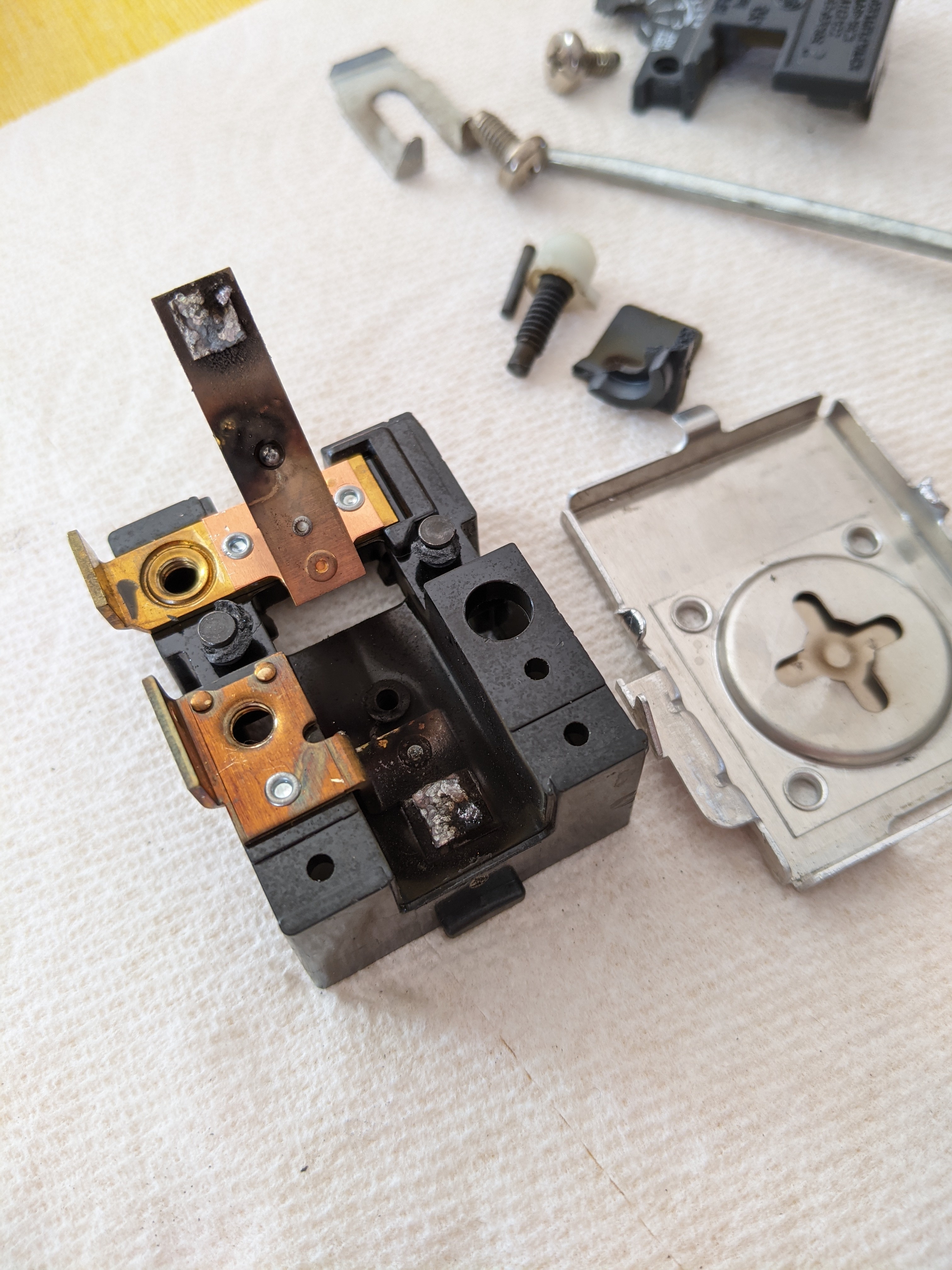 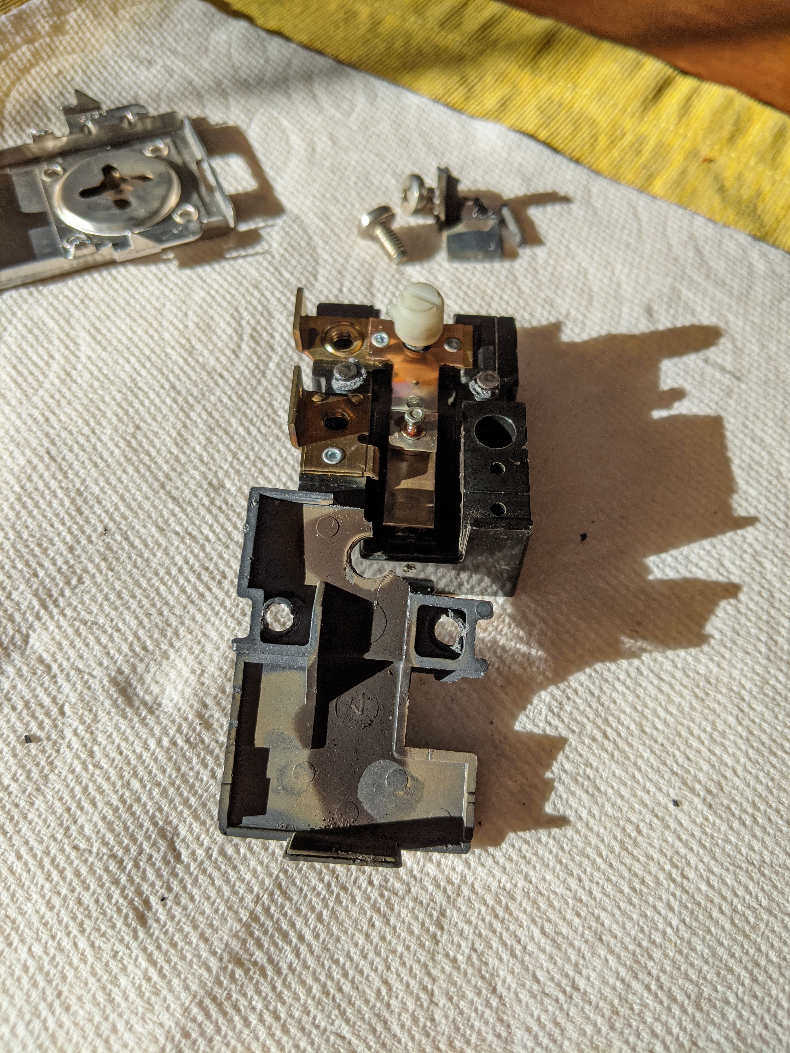
|
|
#
?
Feb 12, 2021 22:21
|
|

|
That filter is small enough that I would expect it to not take time significant time to execute on anything modernish. Probably more of a efficient C question if its running slow. - What kind of chip? - Floating point or integer - How are you organizing the buffer for it?
|
|
#
?
Feb 12, 2021 22:26
|
|
|
ColdPie posted:I have one of those "just curious" questions. Looks like it could be condensed vaporized metal oxides that were exploded off in tiny amounts whenever the thing switched, yeah. I doubt there's any weird magnetism going on though, it's probably just the "shadow" of something that blocked them from settling in particular areas. It's not like there's much convection or air movement happening in a sealed thing like that so the particles probably just travel in more or less a straight line until they stick to something. Shame Boy fucked around with this message at 22:41 on Feb 12, 2021 |
|
#
?
Feb 12, 2021 22:39
|
|
|
ColdPie posted:I have one of those "just curious" questions. Not a forensic electrician by any means, but I believe it's just burned dust. If there's any dust on the contacts when they close/arc, that gets blown up. I notice the same kind of thing on open contacts in (say) food processing places, but a different kind of blackness in a rock quarry. And yeah, because there's basically no air movement except for the displaced air from the arc, it kinda just makes a spray shadow like electron sputtering would.
|
|
#
?
Feb 12, 2021 22:47
|
|

|
It could be that, but then I'd expect it to mostly be concentrated in a circle-ish pattern down near contact pads right? The pads are at the underside of the bottom end of the metal strip in the 2nd photo, but you can see the black stuff goes all the way up to the top of the plastic and even follows the metal strips to the left and right a bit, which is what struck me as odd. If it was a shadow, you'd expect most of it to have deposited on the underside of the metal strip and leave the plastic bare, no? Also are forensic electricians a thing? Oh man, it is. I guess it's probably less awesome than it sounds.
|
|
#
?
Feb 12, 2021 23:05
|
|
|
ColdPie posted:It could be that, but then I'd expect it to mostly be concentrated in a circle-ish pattern down near contact pads right? The pads are at the underside of the bottom end of the metal strip in the 2nd photo, but you can see the black stuff goes all the way up to the top of the plastic and even follows the metal strips to the left and right a bit, which is what struck me as odd. If it was a shadow, you'd expect most of it to have deposited on the underside of the metal strip and leave the plastic bare, no? Eh maybe, I've seen them take all kinds of weird shapes though. It seems the contacts were also covered in the black sooty stuff (especially that lower one in the first picture) but they'd also be moving all the time so maybe they like, shook some of it off? e: Like just looking at this part, it's clear the black stuff is soot coming from the contacts, and the contact is very eroded:  You can also see how there's a little bit of a shadow behind that hole in the upper left but the soot almost "diffracts" around it somehow too. I'm guessing that's how it managed to get "behind" things maybe? Shame Boy fucked around with this message at 23:18 on Feb 12, 2021 |
|
#
?
Feb 12, 2021 23:14
|
|
|
ColdPie posted:Also are forensic electricians a thing? Oh man, it is. I guess it's probably less awesome than it sounds. I remember getting really excited when I first learned that 'forensic accountant' was a real job title.
|
|
#
?
Feb 13, 2021 00:02
|
|

|
Maybe someone here is familiar with repairing laptops and tablets. I'm trying to fix the keyboard on my Cube Mix Plus after all the number row keys including the tilde and backspace, right arrow, and some F keys stopped working yesterday. The only reason I can think of is that some water got on it, not a spill but just a few drops from a cup that I wiped off pretty quickly. I checked under the affected key caps and everything looked ok there, but I can't get from underneath. The metal backing seems to be attached by melted plastic at all the black spots you can see, and the whole thing is very solidly attached to the external casing. Nothing moves at all even if I push on the keys very hard. Could they be just gluing everything to the case?  I can't really gently caress it up because there are literally no replacements available, and I did just replace the battery last week so that would be a bummer.
|
|
#
?
Feb 14, 2021 00:37
|
|
|
mobby_6kl posted:Maybe someone here is familiar with repairing laptops and tablets. I'm trying to fix the keyboard on my Cube Mix Plus after all the number row keys including the tilde and backspace, right arrow, and some F keys stopped working yesterday. That's heat staked on, basically plastic rivets. I'd try softening them up with a heat gun in an effort to keep them semi-intact, you might be able to wiggle the shield off then. I don't think they'd be using glue in addition to heat staking.
|
|
#
?
Feb 14, 2021 13:25
|
|


|
yeah you're right, the shield is only heat staked on, and then the whole thing is then glued to the aluminum chassis. I don't have a heat gun for now but placing it on the radiator did soften up the glue a bit although I still bent the aluminum a bit trying to get it off
|
|
#
?
Feb 14, 2021 18:07
|
|
|
Anyone mess around with the ESP32 much? Trying to get the i2s peripheral to work in awesome mode but the documentation is confusing as hell. Wondering if there's like a blog post somewhere that has a good write-up.
|
|
#
?
Feb 19, 2021 22:10
|
|
|
Anyone have inside info on MCU shortages? STM32 has become mostly unavail at both SMT-assembly houses and retail stores like Digikey and Mouser, other than some low-memory options, or a few odd ones here and there. I'm trying to figure out how to re-design my projects to deal with this, but so many models are out of stock, I can't just switch to a diff one, and the low-mem ones that are left can't handle display buffers. This is frustrating. There are a few models avail across the families, but I don't feel like switching to a larger package just to have it go out of stock too.
Dominoes fucked around with this message at 14:59 on Feb 20, 2021 |
|
#
?
Feb 20, 2021 14:56
|
|

|
I don�t know if there�s inside info to be had. Semiconductor supply is down across the board because of COVID shuttering fabs and generally loving with the supply chain, and demand didn�t decrease along with it. The only specific thing I know about is a fire back in October in a plant in Japan, AKM Semi, which among other things made DACs which of course made the audio market go nuts. I don�t know if that�s still an issue. csammis fucked around with this message at 17:12 on Feb 20, 2021 |
|
#
?
Feb 20, 2021 17:10
|
|

|
I thought car manufacturers are sucking up supplies Dicks
|
|
#
?
Feb 20, 2021 17:35
|
|

|
Everybody in the electronics manufacturing world is doing that the varying degrees of success if (a) they can afford it and (b) their supply chain forecasters can read the tea leaves and chicken entrails correctly. Individual consumers are the ones who are ending up the most hosed for in-demand components because we mostly can�t do either of those things.
|
|
#
?
Feb 20, 2021 18:01
|
|
|
Appreciate the info. I think I'm venting. Switching within the STM32 families isn't a big deal if you keep the same footprint. Switching families can be doable too, although you're probably moving to a sub-optimal solution by doing so. (Ie you picked the family for a reason). Changing footprints obviously requires major PCB changes.
|
|
#
?
Feb 20, 2021 19:30
|
|
|
You could possibly do it with something like this if the problem is long term enough: https://hackaday.com/2019/12/17/tidy-board-rework-uses-flex-pcbs-no-wires/
|
|
#
?
Feb 20, 2021 20:26
|
|
|
Forseti posted:You could possibly do it with something like this if the problem is long term enough: https://hackaday.com/2019/12/17/tidy-board-rework-uses-flex-pcbs-no-wires/ There's an old EEVBlog about designing something like that: https://www.youtube.com/watch?v=jey8NmffhTo
|
|
#
?
Feb 20, 2021 23:39
|
|
|
i knew about the component-linked GPU shortages, i didn't realize they extended to other, less consumer-geared products, but it makes perfect sense. kinda spooky how fragile just-in-time -based manufacturing turns out to be, and how ill-prepared it is for disruptions. on that note, i was curious if the GPU bottleneck was some specific obscure part that you could hypothetically bypass with a discrete-based replacement circuit, but alas it seems to be broader than that: "The main problem is the shortage of components, chips, VRAM modules and even PWM controllers. TSMC, which cooperates with AMD, cannot fulfill complex orders; this Taiwanese company manufactures hardware in three technological processes (3, 5 and 7 nanometers) and has serious problems coordinating everything. Combined with a disrupted supply chains for materials from subcontractors, the picture that emerges is one of production lines that cannot keep up with demand. Samsung, which produces Nvidia's 8-nanometer chipsets reserved for the GeForce RTX 3000 series, can rely on its resources and supply chain to some extent, but even so, it faces its own, albeit not as severe, production problems, including those related to insufficient chip yields. The pandemic is also doing its part. Not everywhere the factories have regained 100% capacity. The extra costs that companies have to incur because of the sanitation regime are also significant. This raises the price of every component that eventually lands in PC hardware. The availability of GDDR6 and GDDR6X memories is also an issue. The demand is huge. Not only because of the new generation of AMD Radeon RX 6000 and Nvidia GeForce RTX 3000 GPUs, but also because of the growing sales of laptops and the debut of the PS5 and Xbox Series X|S. It seems that a bigger problem than the availability of faster GDDR6X memory produced exclusively by Micron for Nvidia is the insufficient number of Ampere GA102 chips on which the top GeForce RTX 3080 and 3090 GPUs are based." (https://www.igorslab.de/en/more-details-and-backgrounds-on-the-scarcity-why-graphic-cards-are-so-hard-to-buy-and-manufacture/) apparently PWM controllers in particular are scarce up and down the board for every application, which is a bit of a problem for society in the digital age
|
|
#
?
Feb 21, 2021 00:47
|
|

|
Another thing of note: JLC (and other SMT assemblers) ran out before Digikey/Mouser (etc?). In the interim, this meant having to hand-solder high-pin packages, and pay more: the retailer prices for ICs are ~1.5x JLC's. Now it's more of a showstopper.
Dominoes fucked around with this message at 07:31 on Feb 21, 2021 |
|
#
?
Feb 21, 2021 07:28
|
|
|
I was going to post this in the Arduino thread, but it has gone dark for the last two months, so I'm hoping someone here might be able to steer me in the right direction. I'm trying to make a prop/cosplay thing that's basically a jetpack with a left and right thruster on it. I'm working on making it play sounds, and I want it to do so in response to the wearer's motion; particularly, I want it to detect if there's a sudden acceleration, play sounds, and increase the intensity of the lights in the thrusters in response. I've already worked out the basics of the lights and the sounds I'm trying to build in. I have a Teensy 3.2 and a Prop Shield on it. The Prop Shield has motion sensing components and the NXPMotionSense library has given me a pretty decent starting point for tapping into that, I think - I was able to get everything calibrated and outputting information for me. The sketch I'm running right now is here: https://pastebin.com/RggJFhpx The output I'm getting seems about in line with what I'd expect. code:And so on. I can see the numbers jump in a relative sense if I move the device around; for instance, in the instant I pick it straight up off my desk: code:I'm guessing that I need to keep a rolling average of values to compare each update against, and if the variation is big enough, assume that the wearer has moved in a sufficient way to trigger the 'jetpack' effect? But I'm at a loss as to how to establish bounds for these values and then compare them. The orientation values are straightforward enough - the SensorFusion filter handles those calculations - but there doesn't seem to be an equivalent simplification of the acceleration/gyroscope values, and frankly, I'm nowhere near math-smart enough to work through this without spending many many days on it. Is there a... more general tool or function or library that I can feed the gyro/accel data into to simplify this task? Failing that, can I get any advice as to where to start picking through this problem?
|
|
#
?
Feb 22, 2021 01:49
|
|


|
My understanding of your problem is that you want to trigger a function on any sudden large acceleration. Here's what I would do: Take the absolute value of AccelX, AccelY, and AccelZ, and add them together. This is because you only care about a large acceleration, in any direction and any axis. code:I'd do this in two steps. Every program cycle, I'd insert the accel value into an array (using the static variable), and then iterate through the array to get a total sum and then divide by elements to get the average. code:code:
|
|
#
?
Feb 22, 2021 02:10
|
|
|
There's an app note for the acceleromter they used on that board that I think does what you want ("Detection of linear acceleration exceeding a threshold"): https://www.nxp.com/docs/en/application-note/AN4458.pdf It's definitely quite a bit to digest though.
|
|
#
?
Feb 22, 2021 03:19
|
|
|
Adding to ante's approach, something that can be helpful in determining thresholds for sensor input is making a series of recordings of what should and shouldn't meet criteria and then comparing them in something as simple as a spreadsheet. Assuming there's a significant difference between your go and no-go conditions, just taking a few measurements for each, averaging them (within group) and setting your threshold to the mid-point is probably a solid start.
|
|
#
?
Feb 22, 2021 03:26
|
|
|
I would: 1) Write down on a piece of paper what motions should and should not cue actions (i.e. hopping forward should turn on lights, hopping backwards should not, running when lights are on should scale light intensity with speed, ...) 2) Edit the code to produce a downloadable series of (time, measurement) points 3) Do each of the motions a few times 4) Download data and plot it. Can you visually tell what kind of motion it is from the plots? How are you doing that? 5) Then think about how to algorithmically make the same kind of decision
|
|
#
?
Feb 22, 2021 03:58
|
|
|
step (5) is doing a lot of heavy lifting there lol
|
|
#
?
Feb 22, 2021 04:11
|
|


|

|
| # ? Apr 20, 2024 06:51 |
|
|
Thanks guys - Ante, I was able to take your pseudocode and I think it's got me rolling now. Figuring out that I'm looking for the absolute combined value of acceleration was a good start. I've got an LED lighting up to indicate when I'm over a certain acceleration threshold, and I think I can get pretty far with that as a way to boost up the lights and sound intensity with a separate decay function over time for those things.
|
|
#
?
Feb 22, 2021 04:35
|
|