


|
Thermopyle posted:Yeah, I'll be recording the data over time. The higher leg will account for 120v load, and I do think that the condenser fans in those units are 120v - though they may be connected to maintain load balance as much as possible. Using the higher number is "close enough for engineering purposes" which I'm assuming is good enough for your test. That being said, to accurately track kwh you need a voltage reference to go with your CT. I'm guessing you have a homebrew setup and aren't doing this because a standalone meter would come with CTs, voltage probes, and instructions on how to connect. But I guess you can get some idea of energy used, with some degree of usefulness?
|
 #
?
May 15, 2020 23:49
#
?
May 15, 2020 23:49
|
|


|

|
| # ? Apr 20, 2024 06:06 |
|
|
angryrobots posted:The higher leg will account for 120v load, and I do think that the condenser fans in those units are 120v - though they may be connected to maintain load balance as much as possible. Using the higher number is "close enough for engineering purposes" which I'm assuming is good enough for your test. I'm...not sure if it'd be good enough! And yeah, it's a DIY setup with an Arduino and some CT clamps. I'm just wanting to figure out how much it costs to run.
|
|
#
?
May 16, 2020 00:05
|
|

|
Motronic posted:Because some handyman or joe homeowner is gonna hook it up to mains voltage. Hrm, my LED lights draw 13W each... times 8... divided by 120... that's <1A... ampacity on a 18 AWG wire is 2 according to this random chart I found...  Motronic posted:There are tons of commercial PDUs that do this. It's quite common. Good ones will make it obvious which 208v outlets are on which phases so you can properly balance. You'll have XY, YZ, and ZX. Seconding Servertech PRO2 line w/ POPS + PIPS + Control + phase interleaving. I have put in hundreds of them over the last few years and they're solid. Just call up Servertech (Legrand now) and tell them exactly what you need, or build your part number right on their site. Moey posted:This new piece of gear in question is a Ciena 8700. I am so, so sorry. (We're working with a Major US Carrier right now to get them to defuck their Ciena garbage. If you've gotten a string of demand maintenance's in the NY/NJ area these past few days I'm not sorry.)
|
|
#
?
May 16, 2020 00:14
|
|

|
Thermopyle posted:I'm...not sure if it'd be good enough! Me either!  I don't think you're going to answer the question that you want. Your setup could compare usage between the HP water heater and a standard resistance electric, but will not accurately give you kwh. Are you looking at an existing installation considering getting one, or wishing to see how your heater compares with EPA estimates or....?
|
|
#
?
May 16, 2020 00:30
|
|
|
H110Hawk posted:I am so, so sorry. (We're working with a Major US Carrier right now to get them to defuck their Ciena garbage. If you've gotten a string of demand maintenance's in the NY/NJ area these past few days I'm not sorry.) I don't have to manage them, this will just live at one of our sites. We are part of some utopian fiber backbone. So far the Waveserver AI units we have are passing traffic fine. But I really am more of an end user on this project.
|
|
#
?
May 16, 2020 01:06
|
|

|
angryrobots posted:Me either! Existing installation. I have multiple reasons and goals. 1. It's just interesting to know how much I spend on hot water. 2. I have my previous water heater hooked up and valved so that I can switch between the two. So, I want to see if and how much money is actually saved with the heat pump model. So, this'll be comparing the complex usage of the heat pump model with the simple usage of the resistive heater model.
|
|
#
?
May 16, 2020 01:12
|
|
|
Moey posted:I don't have to manage them, this will just live at one of our sites. Whatever it takes for you to sleep at night. 
|
|
#
?
May 16, 2020 01:41
|
|
|
Thermopyle posted:Existing installation. That's a very specific use case where you can accomplish basically what you want, I think. You should be able to express the difference between the two as a percentage, although you can't accurately translate that into KWH. I'd be interested to see your results. I was a HP water heater early adopter circa 2010 (IIRC) and I'm still running my all-stainless finish GE geospring. I liked it enough to bring it with me when we moved.
|
|
#
?
May 16, 2020 01:49
|
|
Hi, I got steered here from the electronics thread.  I've built a chicken coop and am trying to learn some stuff about electronics, programming and automation this summer while I am at it. Mainly I am here to try to find out the best way to wire up the system I am planning to make sure it's safe, will last as long as is reasonable and will not burn the coop down. I have a short term and long term goal for the coop. I've got a little experience messing around with car electronics, but have no real training there or with electronics in general so I'm coming from a pretty naive place and trying to learn. Feel free to steer me towards something to read if that helps. This will all be an offgrid 12V DC system more or less. Short term Set up a solar panel and battery to power the coop electronics. (Parts I already have linked below). What I want is to take a Raspberry Pi ZeroW, and have it run a temperature sensor in the coop. I also want it to turn on and off a 12V linear actuator, which will open and close the coop door. For now I just want this to run on command, but eventually will automate it on a schedule. Long term Take all of the above and also run a 150W heating element into an insulated 3-5g waterer inside the coop to keep it from freezing. I live in coastal RI so winters are substantial but not too bad. We can put off discussing this for now unless people have suggestions. I know it's going to take more substantial battery(s) and possibly another panel. I've been able to haphazardly set up a panel and have it charge a small 12V battery which I was able to run through a buck converter and power the Raspberry Pi. The linear actuator hasn't arrived yet and I still am reading up on how to properly get that activated via the Pi. The electronics thread helped me get my head around things so far. 12V, 100W panel - https://smile.amazon.com/gp/product/B01HHDC6NQ/ref=ppx_yo_dt_b_asin_title_o01_s00?ie=UTF8&psc=1 20A PWM charge controller - https://www.windynation.com/Charge-...1319?p=YzE9MTc= Buck converter - https://smile.amazon.com/gp/product/B071FJVRCT/ref=ppx_yo_dt_b_asin_title_o00_s02?ie=UTF8&psc=1 12V Battery (temporary) - https://smile.amazon.com/gp/product/B003S1RQ2S/ref=ppx_yo_dt_b_search_asin_title?ie=UTF8&psc=1 The battery was small and cheap and runs the Pi, I will upgrade later once the system is actually functional and I can figure out how beefy of one will suffice. So I'm thinking roof mount the panel and increase the pitch angle from where it sits on the roof up to 41 degrees which is recommended at my latitude. I'll need slightly longer wires from the panel to the charge controller. Maybe something like this? https://smile.amazon.com/dp/B0753ZLLQB/ref=twister_B084SQBW1M or just buy some more 10AWG and the connectors? The coop roof is corrugated PVC mounted on top of 1/2" thick pressure treated plywood sitting on 2x4 framing. From there the wiring will go to the controller, which will be nearby the battery. The charge controller recommends a 30A fuse between the panel and the controller. Battery and controller will sit in some type of cover and be ventilated. The charge controller clearly defines the amount of space to leave around it etc which I will heed when mounting it. From the battery I'll have to wire the Buck converter and then a USB cable to the Pi. These will also need to be in some type of enclosure but will likely be inside the coop itself (which is out of the weather to some extent). I'll also need to run power from the battery to the linear actuator and to a relay and also wire the Pi to the relay. The temperature sensor will be a 1-wire system directly to the Pi. That's it for the short term setup. So, I know gently caress all about wiring. I have the Black and Decker guide to Wiring and it has a short section on it for wiring a home solar setup. It's using a bunch of junction boxes and conduit. Barring any other advice I'd probably just go with what they did except going through the shingles etc don't apply to this setup well. Best way to drop the wires through the roof? Do I set up the entire system inside the coop itself or put the controller and battery in a separate enclosure? (this one I am curious on because having the system inside the coop might provide some waste heat for the chickens in the winter but if its too much of a fire risk then no) Best practices / best hardware / recommended wiring for wiring different circuits from the battery? What else can I do to ensure that the system won't cause a fire (fusing etc)? Coop interior   There's room to put a shelf etc mid-way up the back wall to store things on (battery(s) if possible)
|
|
|
#
?
May 16, 2020 17:56
|
|


|
Yooper posted:My folks bought a house that has all low voltage controls. The previous owner built it in the 50's and his wife was terrified that the electricity would get her through the wall. It seems the place is well known among local electricians, whenever they come in to where I work they always ask if I'm related to the people with crazy wiring. My grandfather's house had a GE low voltage control system, with multiple control panels through the house (RMS-4A, I believe?). 10 year old me took great joy in cycling through it and hearing all of the relays clunking all at once.  (they were in the attic, but one control panel was close enough that I could hear them..) (they were in the attic, but one control panel was close enough that I could hear them..)Zillow claims it was built in the late 70s, that particular control system seems to be mid 70s. But some of that stuff started coming out in the 50s and 60s. Guessing it's a homebrew setup if the local electricians are familiar with their house DaveSauce posted:What's the go to for LED replacements for tube florescents? FWIW, we have a mix of Osram and Phillips tubes at my workplace (ballast bypass, so straight 208V, AFAIK). They're on 24/7, and have been for a few years now (overhead lighting only goes off during blackouts; the generator only powers lights at the front of the store - it's DARK AS HELL when the generator kicks in, since it's a 120k sq ft store with only the lights over the registers powered by the gen... but not the registers, and no UPS on the registers; linux-based, so they don't take kindly to a sudden power-off). Most of the display coolers that use standard sizes have Phillips or Osram as well. In the year I've worked there, I've only seen one fail (and it still sorta worked... half of the tube went out, it looked weird as hell). All of the overhead stuff is Osram, the coolers that use semi-standard sizes are Osram or Phillips. There's a handful of real T8 bulbs still there, but they're to light up the atriums, and so high up that they're likely waiting for at least half to stop working (~40 ft) before they finally fix them. There's a huge chunk that don't work anymore, I'd hope they'll replace them soon....ish. Most of the electric curtains are also dead up there, at one point they'd raise/lower depending on the time of day to block direct sunlight. The freezers and coolers with doors got some cheap Chinese ones a few months ago, since they're a weird size (5.5 ft), and they're (a) obnoxiously bright and (b) fail often. We've had one go up in flames already. What's odd/funny is depending what part of the store you're in, they have 5000k, 3200k, or 2700k bulbs in the overheads. Most other grocery stores just use 5000k to make it look "even". randomidiot fucked around with this message at 19:27 on May 16, 2020 |
|
#
?
May 16, 2020 19:18
|
|

|
Couldn't find a better place for this, but I've been trying to DIY a Bluetooth Antenna for my PS4. Here's my plan, here's what I've executed, and help I have no idea what I'm looking for. The Plan: Replace the internal Bluetooth Antenna on my PS4 so I never have to look at this hideous monstrosity. Details: 1. Replace Bluetooth Antenna on PS4 with This Antenna 2. Convert odd reverse sexed SMA to Coax. 3. Run coax from PS4 to Wall gang, into bedroom, and mount antenna under soundbar to minimalize clutter our room. What I have accomplished. 1. Antenna obtained and replaced. 2. ???? I don't understand this connection 3. Complete. I have a few adapters in place to... well yeah this connection is weird. What is this SMA connection called? For those of you who are in tune with SMA connections, you probably know that some of these antennas have a male connector with a female wiring insert and the female connector has a male wire insert
|
|
#
?
May 17, 2020 06:47
|
|

|
That looks like RP-SMA male.  But also RF is weird and I try not to touch it because you have to be really careful about cable types and impedances or things just won�t work with no external indication why. corgski fucked around with this message at 07:02 on May 17, 2020 |
|
#
?
May 17, 2020 06:59
|
|

|
corgski posted:That looks like RP-SMA male. Somehow I'm sure, there isn't an RP-SMA Wall Gang Jack =D (time to google) Thank you very much!
|
|
#
?
May 17, 2020 07:20
|
|
|
Ironsolid posted:Somehow I'm sure, there isn't an RP-SMA Wall Gang Jack =D (time to google) I don't know what you mean by "wall gang jack" but Amphenol's connector catalog for reverse-polarity SMA connectors is a good place to look.
|
|
#
?
May 17, 2020 10:27
|
|

|
This might be a plumbing question, but the house that we are buying doesnt have a dishwasher. It was also built in the 60s. What is the current code nationally for dishwashers, because it doesn't look like there are any general addendums for them for my state. I kinda wanted to go hard wired since that is what comes in the box, with an AFCI/GFCI combo breaker. Washer that we want to buy calls for 15 amps.
|
|
#
?
May 17, 2020 19:25
|
|


|
KKKLIP ART posted:This might be a plumbing question, but the house that we are buying doesnt have a dishwasher. It was also built in the 60s. What is the current code nationally for dishwashers, because it doesn't look like there are any general addendums for them for my state. I kinda wanted to go hard wired since that is what comes in the box, with an AFCI/GFCI combo breaker. Washer that we want to buy calls for 15 amps. Tell your dealer to swap you to a plug kit instead of a hardwire. It should be free if they order it for you that way. Or tell em you need $50 more dollars off if the manufacturer is that dumb. Install a dedicated 12/3 run with ganged 20a double breaker to an outlet under the sink next to the dishwasher. Dishwasher gets 1, disposal gets the other. Unless you don't need to do a home run to the panel for some reason or cannot have a garbage disposal due to septic or delicate plumbing.
|
|
#
?
May 17, 2020 19:46
|
|
|
H110Hawk posted:Tell your dealer to swap you to a plug kit instead of a hardwire. It should be free if they order it for you that way. Or tell em you need $50 more dollars off if the manufacturer is that dumb. We have septic so we wouldn�t be doing a disposal. I can see the wisdom of running a 20 for going above and beyond requirements but I don�t think we would honestly ever have a disposal so I think the double hanged 20a is still overkill. Would our situation still mean an outlet is best or hardwired? I think hardwired would be an easier install, but again, I�m open to ideas.
|
|
#
?
May 17, 2020 19:55
|
|
|
KKKLIP ART posted:We have septic so we wouldn’t be doing a disposal. I can see the wisdom of running a 20 for going above and beyond requirements but I don’t think we would honestly ever have a disposal so I think the double hanged 20a is still overkill. Would our situation still mean an outlet is best or hardwired? I think hardwired would be an easier install, but again, I’m open to ideas. The hardest part is running the wire from the panel to the dishwasher. From there plugs are way easier if you ever need to do something crazy like service the dishwasher. Put in 20a regardless but if you're septic then yeah I would skip prewiring the disposal power.
|
|
#
?
May 17, 2020 20:08
|
|
|
Is there a decent surface mount outlet option for under a cabinet or is that a generally a bad idea?
|
|
#
?
May 17, 2020 20:18
|
|
|
KKKLIP ART posted:Is there a decent surface mount outlet option for under a cabinet or is that a generally a bad idea? Just use a handy box. They got holes in the back to screw into the cabinet. The only issue is protecting the NM cable inside the cabinet that is feeding that box. You need to protect the NM from pots and pans being thrown in there. The first option is to put the box at the very bottom of the cabinet and run the NM in with a box clamp through a hole in the bottom of the cabinet. The next option is if your cabinet has a back, then run the NM behind it and feed your box from the back side. The last option is to just use a short section of flex conduit mounted to the box to protect the NM.
|
|
#
?
May 18, 2020 00:48
|
|
|
kid sinister posted:Just use a handy box. They got holes in the back to screw into the cabinet. The only issue is protecting the NM cable inside the cabinet that is feeding that box. You need to protect the NM from pots and pans being thrown in there. The first option is to put the box at the very bottom of the cabinet and run the NM in with a box clamp through a hole in the bottom of the cabinet. The next option is if your cabinet has a back, then run the NM behind it and feed your box from the back side. The last option is to just use a short section of flex conduit mounted to the box to protect the NM. I think future me will really appreciate that I put in a box instead of hardwired it so I probably will just run some 12/2 on a 20a, I wont worry about doing a 12/3 probably since we have septic. Thanks for the help!
|
|
#
?
May 18, 2020 01:05
|
|
|
KKKLIP ART posted:I think future me will really appreciate that I put in a box instead of hardwired it so I probably will just run some 12/2 on a 20a, I wont worry about doing a 12/3 probably since we have septic. Thanks for the help! You would need to run a short section of 12/3 from that box to a switch above the counter if you wanted to do a switched outlet for a disposal. You'd still feed that box from the panel with 12/2. Actually, now that I think about it, you'd be able to use 12/2 for that switch loop since only light circuits need a dedicated neutral. That's assuming that hasn't changed in recent NEC updates. Does anyone know?
|
|
#
?
May 18, 2020 01:12
|
|
|
kid sinister posted:You would need to run a short section of 12/3 from that box to a switch above the counter if you wanted to do a switched outlet for a disposal. You'd still feed that box from the panel with 12/2. Alternatively you can use one of those "air switches" https://www.homedepot.com/p/Garbage-Disposal-Air-Switch-in-Brushed-Stainless-I5580-BS/203499159
|
|
#
?
May 18, 2020 16:12
|
|

|
That Works posted:Hi, I got steered here from the electronics thread. I've helped with a few solar setups, nothing professional or massive. My favorite method of going through the roof is not going through the roof. Instead I'd use seal tite connectors into flexible conduit and enter through a wall. Sealing up corrugated with flashing is going to be challenging. I'd stick it into a vented enclosure inside, think boat battery box. Your waste heat is going to be pretty low here. Best practices will be keeping your poo poo organized, in conduit where it needs to be. That linear actuator is going to eat some DC power and will require a solenoid. So keeping your poo poo straight will be important. I'd circuit break things in groups, one for your solenoid, one for the panel, etc. Again, check out boat circuit breakers as they can handle some moisture and tend to be cheap. Just running a 150w heater will require at least 3 panels at 100w each. Even then it depends how long your heater needs to be on for.
|
|
#
?
May 18, 2020 16:29
|
|


Yooper posted:I've helped with a few solar setups, nothing professional or massive. Thanks! I was thinking running all PVC conduit and boxes with 14awg THNN through all that for most everything downstream of the charge controller. I was also thinking of routing all that through something like this: https://smile.amazon.com/gp/product/B07GBV2MHN/ref=ox_sc_act_title_4?smid=A1Z6QXPXTIWJ5I&psc=1 Would that be cool instead of a breaker? And fusing between the panel and the charge controller and again between the battery and the bus above with these: https://smile.amazon.com/gp/product/B07WC9LB7L/ref=ox_sc_act_title_5?smid=A2ZNPLJCY5BQIU&psc=1 Thumbnail calculations on the heater would only be running ~1-2h total runtime per day and that only when it's quite cold. Also the chickens should generate some heat, so it's hard to estimate. Plan was to just run it as-is this winter (with a larger battery) and see how quickly it depleted the system (or not) and run a separate heater off of house power if needed then re-calculate.
|
|
|
#
?
May 18, 2020 16:36
|
|
|
That Works posted:Thanks! That fuse box would be fine. Your linear solenoid might need some beefier wires depending on the size. I based my heater calculation on 12 hour cycle time (I'm in Northern Michigan), but 1-2 hrs changes it significantly. Keep the moisture out and keep it organized and you won't have problems. Just watch that you don't inadvertently push too many amps through something like that converter.
|
|
#
?
May 18, 2020 17:29
|
|
|
KKKLIP ART posted:This might be a plumbing question, but the house that we are buying doesnt have a dishwasher. It was also built in the 60s. What is the current code nationally for dishwashers, because it doesn't look like there are any general addendums for them for my state. I kinda wanted to go hard wired since that is what comes in the box, with an AFCI/GFCI combo breaker. Washer that we want to buy calls for 15 amps. What state/jurisdiction. In most of CA, the dishwasher and garbage disposal must be a separate circuit, so we'd run a 14/3 or 2 14/2s. Otherwise GFCI + AFCI for a receptacle. Most folks use a wall receptacle.
|
|
#
?
May 18, 2020 18:19
|
|

|
ntan1 posted:What state/jurisdiction. Georgia
|
|
#
?
May 18, 2020 19:44
|
|
Yooper posted:That fuse box would be fine. Your linear solenoid might need some beefier wires depending on the size. I based my heater calculation on 12 hour cycle time (I'm in Northern Michigan), but 1-2 hrs changes it significantly. Keep the moisture out and keep it organized and you won't have problems. Just watch that you don't inadvertently push too many amps through something like that converter. Thanks again. The heater will just be to keep water inside a 2 or 3g insulated container (inside the enclosed coop, with chickens radiating their own heat) from freezing. It's not going to be doing too much but for right now it's too many variables to get a good estimate. So I'll just run it and see how it goes and then decide if I can scale up or if that's economically just unrealistic to do. This is the linear actuator I am waiting on delivery of. https://smile.amazon.com/gp/product/B07HNTPB87/ref=ppx_od_dt_b_asin_title_s00 12V 3A. Shouldn't be too taxing on the system. My next homework is to figure out how to get a Raspberry Pi to run a relay that activates this (and which relay to buy / how to install). Reading up on that now generates a lot of conflicting advice, but I figure that's more a question for the Pi or Electronics threads.
|
|
|
#
?
May 18, 2020 21:44
|
|
|
This whole post: https://imgur.com/gallery/mUFHQoQ
|
|
#
?
May 19, 2020 01:34
|
|


|
Man do I have a head-scratcher: So, a remodel. A couple bathrooms, a bedroom. No biggie. Basement bathroom was gutted, and I roughed it all in. It was on two 20amp circuits (unlike the upstairs bathroom that was on one circuit with a shared a neutral whole 'other story) one for receptacles, one for lights. Bathroom lighting circuit also feeds a room next to it, lights, a closet outlet. And one other thing I'll get to. Again, all roughed in, on an AFCI breaker. Everything fine. Get a call today the breaker won't reset. I go back, open up everything, even things I never worked on/touched, start troubleshooting, adding things back one by one. I removed the AFCI breaker and put in a regular one. All "cool". Back to the AFCI breaker and when I test all the hots to ONE neutral - BAM. Find out the aerator for the septic (and theres been a huge septic problem at this house) is causing the trip. Its the neutral for that that tripped. Outside, there has also been a bunch of excavation for the deck. I've found some cut wires there but not the septic feed. Still, something is shorting out that AFCI breaker. I have not opened up any of the septic hatches. I have only begun to explore the underside of the deck - in the rain, in the mud and that makes it difficult (also, the giant turd some guy left out there). Inside theres the aeration box and another box below it with a switch, without a fuse, and a bare wire hanging loose. Then the feed going down and out to the septic. There are three different general contractors on this job - the one I work for doing the inside work, the deck foundation repair, and the septic issue. Good luck finding anyone to give me an answer. Now, I obviously don't want the septic aeration on the bathroom circuit. so we can get that out of the way. Ive got everything inside working but do need to get this septic thing running. What am I missing? The aeration system didn't trip the AFCI before, so im guessing excavating crew nicked something?
|
|
#
?
May 19, 2020 01:37
|
|

|
Bad Munki posted:This whole post: https://imgur.com/gallery/mUFHQoQ It's amazing what a loose terminal screw can do. An electric arc is one of the hottest things in the known universe, and a conventional breaker will happily let a small one go on for more than long enough to melt plastic insulation and receptacles. What gets me is that nobody notices the smell. Ozone and melted plastic is not something someone with a functional nose and brain just ignores.
|
|
#
?
May 19, 2020 02:53
|
|

|
That�s why I�m so glad AFCIs are being mandated in just about every habitable room in residential construction, somehow people just don�t think that their bedroom smelling like the copier in their office is a problem. Sorry not sorry about your nuisance trips.
|
|
#
?
May 19, 2020 04:17
|
|
|
corgski posted:Sorry not sorry about your nuisance trips. In my experience, anything that nuisance trips is a special case and I'd rather just have a dedicated outlet for it anyhow. Like, the dust collector in my shop, and my miter saw. They both nuisance tripped like mad, but they're on dedicated outlets now, so no problem.
|
|
#
?
May 19, 2020 16:21
|
|
|
The wife went to take a bath this weekend and the pumps weren�t working. I checked the breaker and the CFCI outlets and everything was good. I was getting ready to look at the pump but checked the heated floor panel and that won�t turn on along with an outlet directly outside in the hallway. I rechecked all the CFCI including the exterior ones and went the the circuit panel and everything looks good. If the hallway outlet went bad could that prevent the tub and floor from getting power? My next step was to put a new receptacle in but maybe their is something else I should look at first?
|
|
#
?
May 22, 2020 15:18
|
|


|
What do I need to do/have on the AC side of a permanent in-car inverter system to make it quality and safe? I'd like to have a couple outlets available for passengers and a couple in the cargo area. I think I'd want a fuse on the DC side and breakers on the AC side. What does the AC earth connect to? Do any xFCI devices work? Eventually I'd want to have a way to connect to shore power. Thoughts on doing that by charging the battery vs bypassing the inverter and connecting shore ac to car ac? The former seems a lot simpler if the efficiency and power limits aren't a problem. e: do I need conduit or some kind of enclosure for the AC runs?
|
|
#
?
May 22, 2020 15:48
|
|


|
It might not be the outlet but a burnt out wire. I'd start checking at that outlet that doesn't work.taqueso posted:Inverter stuff All of the AC inverters I've seen have the outlets directly on them. The problem is that extension cords aren't allowed for permanent use. kid sinister fucked around with this message at 16:00 on May 22, 2020 |
|
#
?
May 22, 2020 15:54
|
|
|
I believe inverters for RVs and boats or industrial inverters are available with terminals instead of outlets. I can look into that more today but for now we can assume this won't have an extension cord. e: quick example: 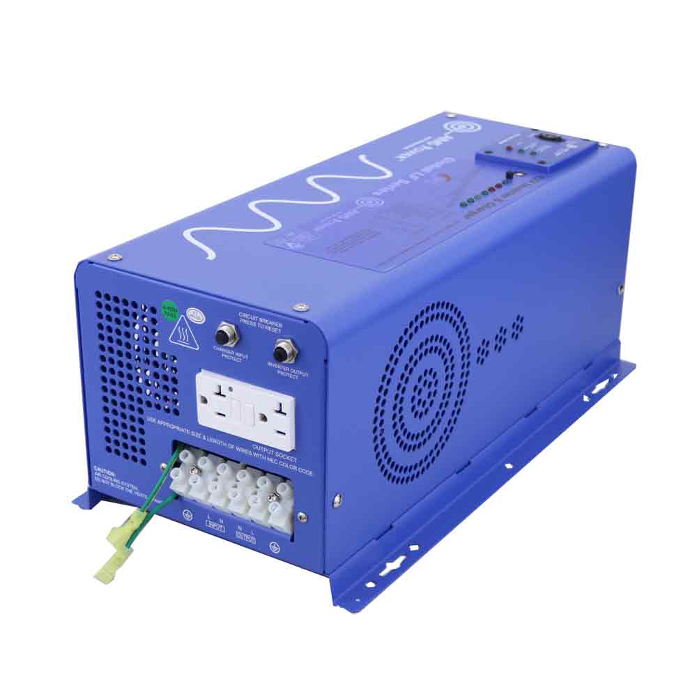
taqueso fucked around with this message at 17:28 on May 22, 2020 |
|
#
?
May 22, 2020 16:05
|
|
|
Yeah boat/RV power systems would be what to emulate here. In our last RV it was actually a combination inverter/converter/charger unit that had its own built in transfer switch so shore power was already covered in the same box. Just poking around a few inverter vendor sites it looks like a lot of them either have built in GFCI as standard or as an option so you might not have to worry about that as a separate thing. wolrah fucked around with this message at 18:12 on May 22, 2020 |
|
#
?
May 22, 2020 18:10
|
|

|

|
| # ? Apr 20, 2024 06:06 |
|
|
Homeowner did a real solid when we asked them to update from a fuse box to a circuit breaker before closing. All circuits are AFCI as code required but they spent a bit extra and did the combo AFCI/GFCI breakers so I don�t feel as super rushed for updating my outlets. Also installed new grounding rods and upgraded the service to 200 amp. Still need to get the main line to the oven on 6AWG cable, but it is a relief that they spent the money on quality instead of attempting to cheap out.
|
|
#
?
May 23, 2020 16:21
|
|