


|
This feels like maybe something I should know but I don't... I opened up a 4-gang box today to do whatever. All romex with little bits left as sleeves that were marked. Standard. Marked like this: Cans (recessed, dur) Corner Flood (outside) Floods (others outside) Porch Feed Feed (I know, why two?) SRC What the hell is SRC? Should I know that acronym? Also, it was the hot. This whole house is a mess. Lotsa of attic fun in this heat.
|
 #
?
May 29, 2020 00:04
#
?
May 29, 2020 00:04
|
|


|

|
| # ? Apr 26, 2024 08:44 |
|
|
Ferrule posted:This feels like maybe something I should know but I don't... Source maybe?
|
|
#
?
May 29, 2020 00:30
|
|

|
Likely source, with two downstream feeds.
|
|
#
?
May 29, 2020 02:26
|
|


|
 "The bake oven doesn't work." Oddly enough there's not a power imbalance relay either so it just kept working the other two coils until it was just one coil. ~50kw oven.
|
|
#
?
May 29, 2020 14:13
|
|


|
Source makes sense. Probably not his I would have marked it. Again, just checking on an acronym that maybe I missed., thanks.
|
|
#
?
May 29, 2020 14:18
|
|
|
Yooper posted:
Thank goodness they cleaned before you arrived, imagine what it would have looked like had they not.
|
|
#
?
May 29, 2020 16:22
|
|
|
ncumbered_by_idgits posted:Thank goodness they cleaned before you arrived, imagine what it would have looked like had they not. The joys of industrial. That wasn't too terribly bad. Opened a 4X box once to find it contained about 4 gallons of hydraulic fluid. Stinky. Old. Nasty. Rancid. Oil. I've still got tools that have that smell on them from that machine.
|
|
#
?
May 29, 2020 16:44
|
|
|
That reminds me of doing electrical work on boats. Not giant ships mind you, just the little fishing boats, like 3 people max. The battery is always in the bilge. For those of you without your sea legs, the bilge is the lowest part of the hull near the back. Due to how hulls are shaped, everything collects there: water, oil, trash, leaves, insects, fish guts... You can imagine the smell.
|
|
#
?
May 29, 2020 17:09
|
|
|
Yooper posted:
This looks like something out of the beginning of a Marvel movie.
|
|
#
?
May 29, 2020 19:01
|
|
|
So I was working in my pond, and I felt a little tingle like I pinched a nerve. On a hunch I pulled out the Fluke and I'm showing 40VAC between the water and the wet dirt next to it. I'm guessing the pump (magnetic drive impeller) is failing somehow, as a break in the main insulation would probably be much more catastrophic, but I'm a little surprised that a short I'm able to feel like that isn't tripping the (tested) GFCI. Is this a common failure mode for old pond pumps? Is the 40V indicative of one winding phase being exposed or something?
|
|
#
?
May 30, 2020 21:06
|
|

|
Is it a submersible pump? If so, I'd certainly consider it possible that it's able to energize the water. I assume you tested the voltage differential with the GFCI tripped and/or the breaker for the circuit off? If so, do you have another GFCI you can swap in to test with? It's possible to get a very slight tingle from a current low enough not to trip the GFCI (<5mA), but being able to measure that high of a voltage differential implies there's potentially a dangerous situation going on.
|
|
#
?
May 31, 2020 00:44
|
|

|
B-Nasty posted:Is it a submersible pump? If so, I'd certainly consider it possible that it's able to energize the water. Submersible pump, yeah. Tested with the circuit live/pump running -- of the GFCI were tripped, there'd be no current? Anyways, I ordered a replacement, just curious.
|
|
#
?
May 31, 2020 01:35
|
|
|
Hubis posted:Submersible pump, yeah. Tested with the circuit live/pump running -- of the GFCI were tripped, there'd be no current? I was just wondering if you ruled out the obvious and confirmed it was actually an issue with that circuit specifically. Did you test continuity between ground and the metal body of the pump?
|
|
#
?
May 31, 2020 13:47
|
|
|
I just installed an attic fan (QuietCool ES-3100). It has a 3-speed motor, the kind with 3 sets of windings. I want to automate it, since right now I have a power cord dangling out of my attic and that's dumb. I already have a Z-Wave hub, but I haven't found any 3-wire controllers (presumably they all use triacs for dimming). I could make something with a Raspberry Pi & relay board, and shove all that into a PVC work box, but I'm hoping that there's a premade solution closer to market and perhaps more compatible with insurance. All I need to do is connect 1 of 3 different wires to load, while keeping them exclusive of each other (so 1, 2, OR 3 can be connected, but not 1 AND 3).
|
|
#
?
May 31, 2020 17:09
|
|
|
 There is no wingnuts in the box, except 1. All 3 romex cables going into the box have wires going directly into the 3way switch. I have absolutely no idea how they got this wired up in the first place. I just want to replace the switch with an identical unit.
|
|
#
?
May 31, 2020 19:16
|
|

|
street doc posted:
thats a triple decora switch, correct? Hard to tell from the angle but it sure looks like it. By 3-way you mean it has three switches on it, correct? So three of those wires are switch legs (on going to each light - I assume there are three lights) and the other is the hot.
|
|
#
?
May 31, 2020 22:12
|
|
|
Ferrule posted:thats a triple decora switch, correct? Hard to tell from the angle but it sure looks like it. By 3-way you mean it has three switches on it, correct? So three of those wires are switch legs (on going to each light - I assume there are three lights) and the other is the hot. Yes, should have been more clear. Three switches. I�m fine cutting the wires and putting in a standard switch, it just bothers me that I don�t know how they put the original in. Maybe there is a way to remove the back cover?
|
|
#
?
Jun 1, 2020 00:32
|
|
|
It's got to be wired with some kind of backstabs, there should be a way to release the wires non-destructively, can you show a picture of the backside?
|
|
#
?
Jun 1, 2020 00:36
|
|

|
street doc posted:Yes, should have been more clear. Three switches. I’m fine cutting the wires and putting in a standard switch, it just bothers me that I don’t know how they put the original in. Maybe there is a way to remove the back cover? But it's a pain in rear end, and as long as you've got a little extra length on the wires in question, it's easier to just snip them off as close to the switch as possible.
|
|
#
?
Jun 1, 2020 01:01
|
|

|
street doc posted:Yes, should have been more clear. Three switches. I�m fine cutting the wires and putting in a standard switch, it just bothers me that I don�t know how they put the original in. Maybe there is a way to remove the back cover? Imma gonna give like a bare bones lesson. Outlets lights whatever, need two things, a hot and a neutral. Power flows through the hot and flows back through the neutral. Lets not get into why. An outlet has a hot and neutral - black wire, white wire. Power is constantly there. A light needs a hot and a neutral. It would always be on if it was connected like an. outlet . But a switch is an interrupter - its a hot on one side and another wire, a "switch leg", that goes to the light. All the switch does is connect or disconnect the flow. That device you have there controls three different things (lights, im assuming) - there is a single hot that is making the connection for whichever light is connected to the switch. Do you want all three things to come on with flip of a single single switch?
|
|
#
?
Jun 1, 2020 01:31
|
|
|
insta posted:I just installed an attic fan (QuietCool ES-3100). It has a 3-speed motor, the kind with 3 sets of windings. I want to automate it, since right now I have a power cord dangling out of my attic and that's dumb. This https://www.amazon.com/dp/B07PFLPTY4/ref=cm_sw_r_apa_i_wFf1EbKGXYQQK Or https://www.amazon.com/dp/B01G7OD1F8/ref=cm_sw_r_apa_i_1If1EbBM924N4 Both Will be easier than cramming a pi and relays into the ceiling.. This might help https://thesmartcave.com/smart-ceiling-fan-control/
|
|
#
?
Jun 1, 2020 02:25
|
|


|
tater_salad posted:This I was impatient and already started the Pi (really, ESP32) solution. It's not an issue of "cram it into the ceiling", since it's an attic fan and I have my whole-rear end attic to use. The products you suggested still don't seem viable for speed control -- the manual specifically calls for switching between windings to select HIGH/MED/LOW speed. I currently have a NEMA work box with knockouts and NM-B 14/2 & 14/4 clamps. The plan is for the 14/2 to enter the enclosure, go through a 10A glass fuse on line, and then use wire-nuts to connect to stranded & tinned conductors internally. A single run of 14/4 will go to the motor, since that will handle the 3 windings I need. I need to use a stranded run to the motor, since by design it is floating and vibrates slightly. The ESP32, little power supply, and relay board will all be behind the fuse and enclosed in the NEMA work box. What additional steps should I take for security and/or compliance? edit: for what it's worth, the fan draw is approximately 300 watts on high. insta fucked around with this message at 03:44 on Jun 1, 2020 |
|
#
?
Jun 1, 2020 03:37
|
|
|
insta posted:What additional steps should I take for security and/or compliance? Local disconnecting means. Put a switch before your fuse so you can cut power off. Light switch will be fine.
|
|
#
?
Jun 1, 2020 11:03
|
|

|
babyeatingpsychopath posted:Local disconnecting means. Put a switch before your fuse so you can cut power off. Light switch will be fine. It's not too late for me to switch the design over to a plug, using an IEC C13 socket module with the little switch & glass fuse embedded. Is that preferable? Feels sorta weird having an outlet in a box just hanging near a rafter in my attic and computer cord there, but that certainly would otherwise satisfy a few layers of "disconnect".
|
|
#
?
Jun 1, 2020 13:52
|
|
|
For rewiring rooms I see a few places say to do it behind baseboards which seems like a good non-destructive method. My general plan is to do that and maybe some sort of armored raceway and the wire guards you put on studs as I come to them. Any real issues with this?
|
|
#
?
Jun 1, 2020 17:40
|
|


|
KKKLIP ART posted:For rewiring rooms I see a few places say to do it behind baseboards which seems like a good non-destructive method. My general plan is to do that and maybe some sort of armored raceway and the wire guards you put on studs as I come to them. Any real issues with this? It's really tedious. Drilling up or down from a basement or attic respectively is always preferred.
|
|
#
?
Jun 1, 2020 19:10
|
|
|
Bad Munki posted:I'm thinking something like this might be my best bet: Had an electrician out today, the proposed solution is a combination of the above plan and what, uhhhhhhhhhh, one of you, I forget who, said: they want to dig the service line back far enough that they can shift it over to come up under the bump out there, just run that up as the new service entrance with a meter there, and then run conduit over to where the pre-existing meter will have been, and then run off to the panel from there. It appears the service is in conduit all the way to the main panel, as it should be, so hopefully it won't be too hard to run new wire there, but he said if that fails, they can put a (slightly smaller) box where the service enters the house and hook up there. $1800, covers parts, labor, digging, permitting, etc, the whole shebang, I just stand there and drink beer. Any opinions on where that quote stands? This is in Iowa.
|
|
#
?
Jun 1, 2020 20:01
|
|


|
Bad Munki posted:$1800, covers parts, labor, digging, permitting, etc, the whole shebang, I just stand there and drink beer. Any opinions on where that quote stands? This is in Iowa. Sounds reasonable. Any time a plumber or electrician has to pull out a shovel, that bill is going to get ugly. Considering there is no DIY option for this, that quote is not nearly as bad of a gouge as they probably could've gotten away with in many areas.
|
|
#
?
Jun 1, 2020 20:42
|
|
|
Quick (hopefully) question. Previous owner of house, for their "wall mounted TV", simply cut a vague square in the drywall and ran an extension cord and HDMI cables through it down the wall (right above what used to be a wood fireplace, now gas + ducted!) and to the little cubby where media equipment was. No bueno. What I want to do: * put in a quad RJ-45 wall box for various streaming devices (easy enough, have all the stuff to do this) * put 1, maybe 2 conventional outlets on the wall, and run Romex down the wall to the little cubby area (where existing outlet was poorly installed, but at least it's being fed properly by a Romex line from... somewhere My question is, I also have a rather nice Furman PST-8 conditioner that I actually want to run the things plugged above on the wall (i.e., LG OLED) off of. A male to male power cable scares the poo poo out of me and is generally a terrible idea. What is the proper way for me to connector-ize getting Romex coming out of the wall to a male AC plug? Is there some kind of psuedo-standard recessed female receptacle I could use (like a wall mount IEC C13?). That circuit by definition cannot be live until I plug it into a source, so it having exposed male pins is likely fine. I feel like what I'm asking here is a connectorized / field-jointed way to get from Romex to 5-15P. tl;dr � I wish to go NEMA 5-15 Outlet -> Romex -> (?) -> NEMA Receptacle on a power conditioner. What should I do for the (?)? Also, jesus, fishing cables I feel like is impossible. I cannot tell how the wizards did anything at this place. I'm afraid of giant flexible drill bits but as far as I can tell, they did not have to do drywall cuts to run some cable which is amazing. e: this is the conditioner, I don't think it is reasonably small enough to locate behind the TV nor is it (of course) a good idea to tuck it into the wall... e2: Maybe I'm a dumb dumb and could just use the same kind of thing I've seen on boats, a recessed male outlet? movax fucked around with this message at 01:23 on Jun 3, 2020 |
|
#
?
Jun 3, 2020 01:15
|
|

|
movax posted:Quick (hopefully) question. The NEC relaxed the rules on in wall extension cords for TVs, barely. The only one allowed is for a monoplex outlet and inlet, with standard NM ran between them. Then, you just use a standard 3 prong extension cord to power the inlet. The inlet and outlet can be recessed, it's your call. Companies make kits for this. Sometimes you need to supply the NM. Keep in mind that there are some kits for sale that are not allowed. If it has a cord for the inlet that connects to the NM in the wall, that's not allowed. If it has a duplex outlet, that's not allowed. Remember, it's in wall extension cord, not power strip. You'd have to run your Ethernet in a separate box or a divided box. Also, I've always liked the wall mount TV box choices from Arlington the best, especially their recessed boxes. Poke around their website. They have LOTS of choices.
|
|
#
?
Jun 3, 2020 01:55
|
|
|
Hoping to safely fix an accident. I decided to redo landscaping at my house and cut this nasty weed underneath a huge bush. I pulled the weed and cut it again so I had a nice big chunk. As the dirt fell off - boom - it�s an electrical wire run to my outdoor lamp post in front of my house. So now I removed a chunk of that wire which was not in a conduit and a mere 2 inches in the dirt. It�s a UV shielded wire so I believe this is ok not to have in conduit. My question is how can I safely connect it again? I have found some splicers that I could purchase with some new electrical wire and then heat a conduit to seal it around, repeat for the other end from the new wire and bury this instead. Or would I be better off repurposing the wire and connecting it to an outdoor receptacle and teeing off of that to do a new run to my lamp post? I�m trying to avoid a new long run into the house since that can be dicey but also, I don�t want to burn the place down.
|
|
#
?
Jun 6, 2020 00:25
|
|

|
Slagwag posted:Hoping to safely fix an accident. I decided to redo landscaping at my house and cut this nasty weed underneath a huge bush. I pulled the weed and cut it again so I had a nice big chunk. As the dirt fell off - boom - it’s an electrical wire run to my outdoor lamp post in front of my house. So now I removed a chunk of that wire which was not in a conduit and a mere 2 inches in the dirt. It’s a UV shielded wire so I believe this is ok not to have in conduit. Can you post a picture? Are you sure it's a 120VAC circuit and not low voltage (12VDC? 24VDC? I'm not sure what is used for landscaping)? It being buried so shallow and so easy to sever makes me think it's the latter (in which case the risks and repair may be simpler).
|
|
#
?
Jun 6, 2020 02:59
|
|
|
Does anyone have a handy link or name for the best type of box and outlet to use under my sink so I can wire that poo poo up? It needs to be externally mounted, so I plan on using a bit of conduit (plastic would be preferable) so is there a more "water resistant" box that I need to use or do I just get one of those gray plastic boxes, a faceplate, and some schedule 40 conduit? I am thinking something like this "weather resistant" 1 gang non metallic box screwed into the back of the cabinet, this terminal adapter, and a bit of this conduit and some cable straps to keep it nice and happy. Is there an outlet cover that has foam or anything that would be better about keeping water out the box? KKKLIP ART fucked around with this message at 02:10 on Jun 9, 2020 |
|
#
?
Jun 9, 2020 01:56
|
|
|
I don't know the relevant code for under sink outlets, but most of the ones I've seen installed were just regular metal handy boxes with a piece of armored cable powering it. Presumably the MC cable goes into the basement and then into a junction box where it ties into a regular NM cable. I'm guessing that even though under the sink is intuitively a 'wet' area it doesn't need waterproof connections since it should only see the occasional spray / leak and won't ever be immersed or rained on for 12 hours straight.
|
|
#
?
Jun 9, 2020 13:44
|
|
|
Hubis posted:Can you post a picture? Are you sure it's a 120VAC circuit and not low voltage (12VDC? 24VDC? I'm not sure what is used for landscaping)? It being buried so shallow and so easy to sever makes me think it's the latter (in which case the risks and repair may be simpler). So the cable itself says: 'ETTCOFLEX 14-2 - TYPE UF - WITH GROUND WIRE'. I found it at home depot and bought 25ft: https://www.homedepot.com/p/Southwire-25-ft-14-2-Gray-Solid-CU-UF-B-W-G-Wire-13054221/202316486 That is exactly what is underground. The link also states: '#14 AWG undgerground wire for lamp posts, pumps and other loads' and ''UF outdoor direct burial wire is resistant to moisture and light'. So looks good though I don't think it is low voltage. I also could not find this at home depot or a local hardware store but I did find this on Amazon: https://www.amazon.com/gp/product/B00004WLKR/ref=ppx_yo_dt_b_asin_title_o00_s00?ie=UTF8&psc=1 - Gardner Bender HST-1300 Underground Cable Kit for Waterproof 14-8 AWG UF Copper Wire. This seems to be exactly what I need but tough to tell from pics if it will handle all wires necessary but I will give it a shot.
|
|
#
?
Jun 10, 2020 20:47
|
|
|
You're looking for UF-B. It's pretty common. Whoever installed that wire is an idiot. That splice kit should work, so long as you clean the wire carefully and use enough heat to melt the glue lining and shrink the tube evenly. I dunno how many conductors that is for, though. It looks like one splice and one piece of heatshrink, which covers one conductor.
sharkytm fucked around with this message at 12:13 on Jun 11, 2020 |
|
#
?
Jun 11, 2020 12:10
|
|
|
sharkytm posted:You're looking for UF-B. It's pretty common. Whoever installed that wire is an idiot. That splice kit should work, so long as you clean the wire carefully and use enough heat to melt the glue lining and shrink the tube evenly. I dunno how many conductors that is for, though. It looks like one splice and one piece of heatshrink, which covers one conductor. Amazon stock photos stink. I received the kit after 1 day which was surprising. The connector is a round barrel with room for 4 conductors. The cable I have looks like this: 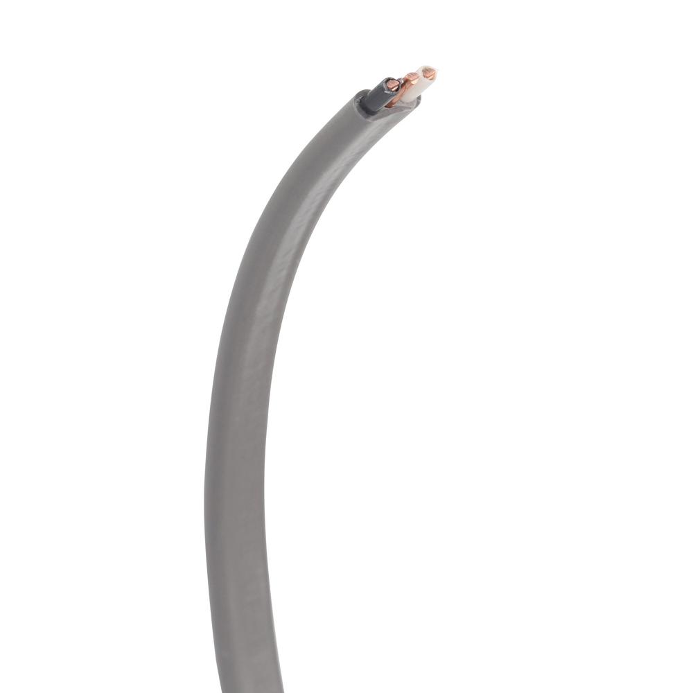 So I believe that is two conductors + a ground wire. I assume that with the splice kit I connect both conductors and the ground wire into the it. Should be easy enough to test out and see if it works.
|
|
#
?
Jun 11, 2020 22:02
|
|
|
Have a problem with post lights. Two work, two don't. I've traced everything to the best of my ability. Not sure if homeowner is going to want their (giant) front yard trenched (and possibly one of the driveways). Solar seems to be a solution but wow are those expensive. Anyone have experience with solar post heads? Good brands? Good life? Etc. And if anyone wants I can draw a rough idea of the location of these if anyone else wants to lose sleep like I have been.
|
|
#
?
Jun 11, 2020 22:07
|
|
|
Question about wiring undercabinet LEDs: I have a dimmer switch that will feed my LED driver, which will then feed four undercabinet lights. The driver is 120VAC-->24VDC, and I ran 18AWG wires for them prior to cabinet installation. I finally received the driver in the mail yesterday, and realized that both the input and output terminal blocks say they only accept 16-18AWG. I assumed the line side terminal blocks would be sized for 12-14AWG since, you know, that's what normal lighting circuits are powered by. Looking at the manufacturers guide, located at: http://www.lutron.com/TechnicalDocumentLibrary/369543_ENG.pdf I see that on page 66, it tells me to use a wire nut to connect a short piece of 16-18AWG to my feed wiring, and plug that into the terminals on the LED driver. I will post the picture when I get home, can't access imgur at work right now, but it's basically: Feed 12-18AWG --> wire nut --> 16-18AWG --> LED Driver --> 16-18 AWG --> wire nut --> 12-24AWG LEDs The next page even has this note: Lutron posted:Terminal blocks on the drivers accept only solid 18 AWG or 16 AWG (0.75 mm2 or 1.5 mm2) wire. To use wire gauges larger or smaller than this terminal blocks� rated gauge of 18 AWG or 16 AWG (0.75 mm2 or 1.5 mm2) refer to the Terminal Wiring Gauges diagram on the previous page. Connect up to 3 ft (0.9 m) of 18 AWG or 16 AWG (0.75 mm2 or 1.5 mm2) wire to the LED driver terminal blocks, then connect 14 AWG to 12 AWG (2.5 to 4.0 mm2) or 24 AWG to 20 AWG (0.20 mm2 to 0.50 mm2) up to the length allowed in the above table."
|
|
#
?
Jun 12, 2020 12:21
|
|

|

|
| # ? Apr 26, 2024 08:44 |
|
|
Viper915 posted:To me this seems wrong. The circuit it is connected to is on a 15A breaker at the panel, and 16AWG is only rated to 10A, so if there is a fault in the driver, wouldn't that be a fire risk? It shouldn't be an issue if all of the connections and smaller gauge wire are in a box. It's pretty standard for those recessed LED lights to have a metal enclosure with a Wago-clone inside that you pop your 14g NM wire into, and it already has the driver's smaller gauge wire inserted. Even something like a floor lamp usually uses 18g stranded wire, which can only carry like 5A max. You do not want to transition to a lower gauge wire and have a length of that running in a wall or other inaccessible location.
|
|
#
?
Jun 12, 2020 13:43
|
|