


|
Improvements (hopefully) coming to the build log photo's... I got a new toy today! One final slightly out of focus (somehow appropriate) picture from the old Canon point and shoot: 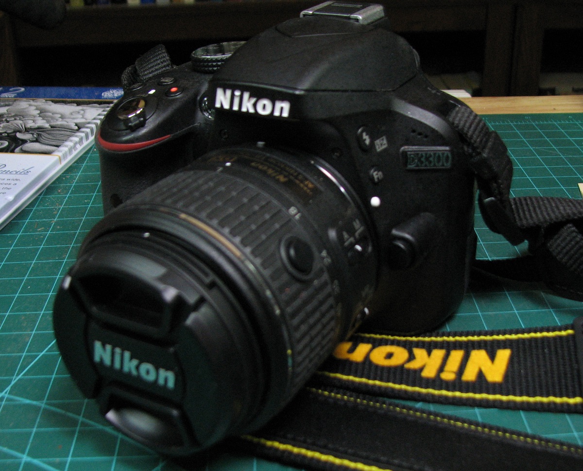 I continued working on the cap rails, first placing the rest of the port side on to match the already completed starboard side. The scarf joint on this side came out great, with only a tiny gap on the inside edge (which you couldn't even see in the picture from the old camera). 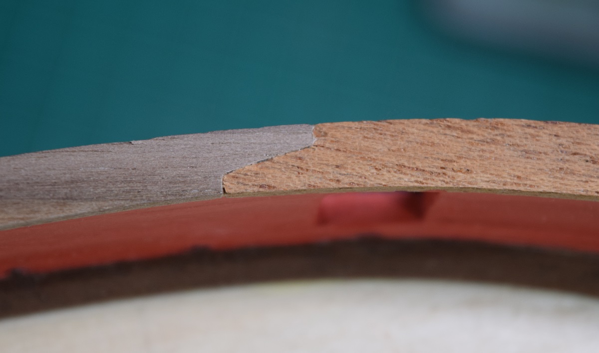 I managed to trim the main kit piece of the cap rail too short, so I had to add a small shim at the back end of it, but it will pretty much be covered up (except edge on) by the vertical piece at the quarter deck step. After completing the main cap rail, I added the stern bulwark planking above the cap rail. For this I used two 1/8" x .030 strips, and left them full width at the stern, and tapered them down to about 1/2 width at the front edge. 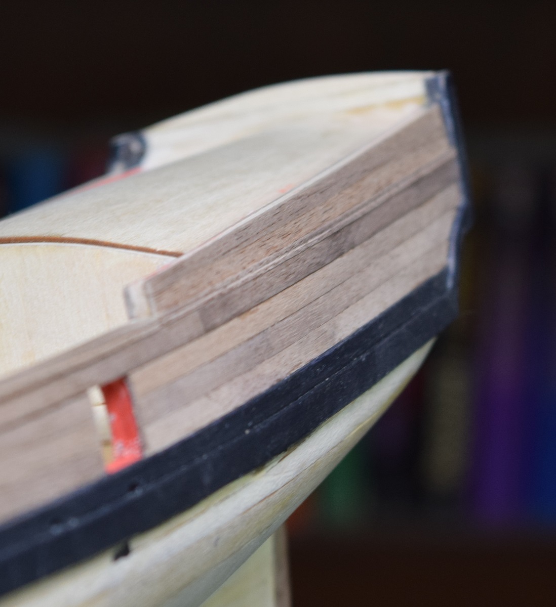 Once those planks were done, I sanded the edges level for placement of the upper cap rail along the poop deck. This requires the placement of a vertical piece to cover the front edge of the bulwarks at the quarter deck. I decided to do my fancy edging (if a single line can be called fancy) on the upper cap rail, and I did it on all three exposed edges. 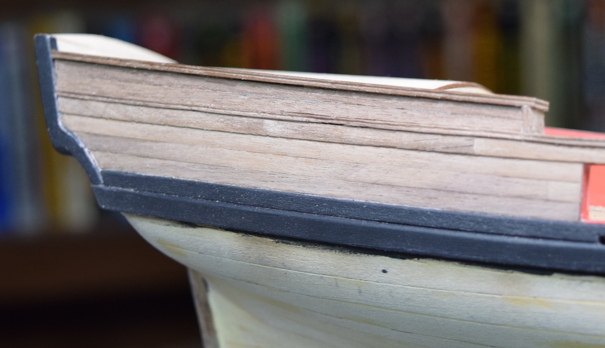 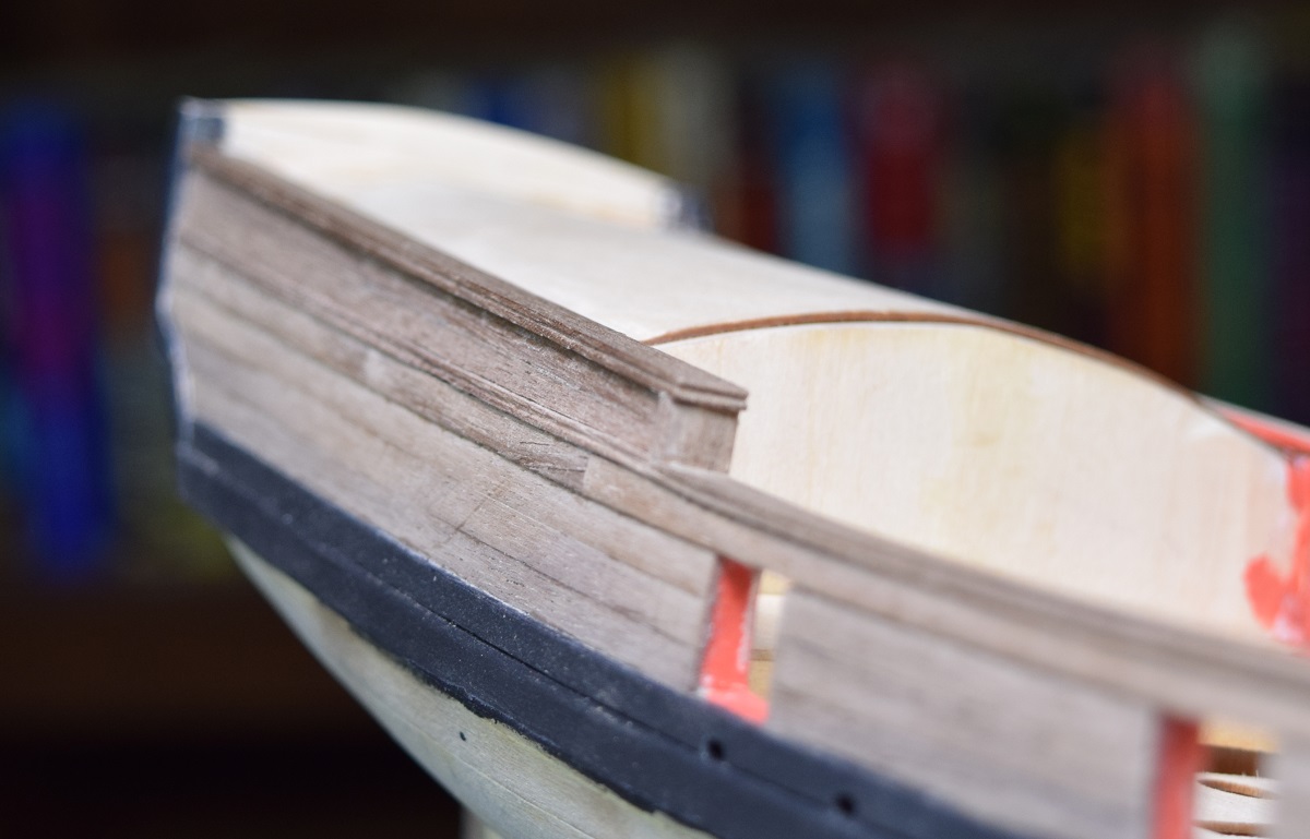 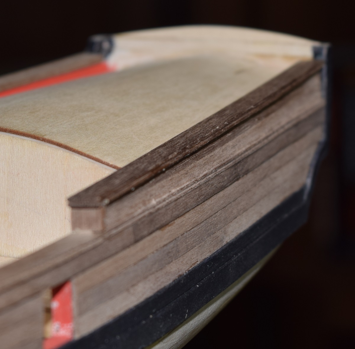 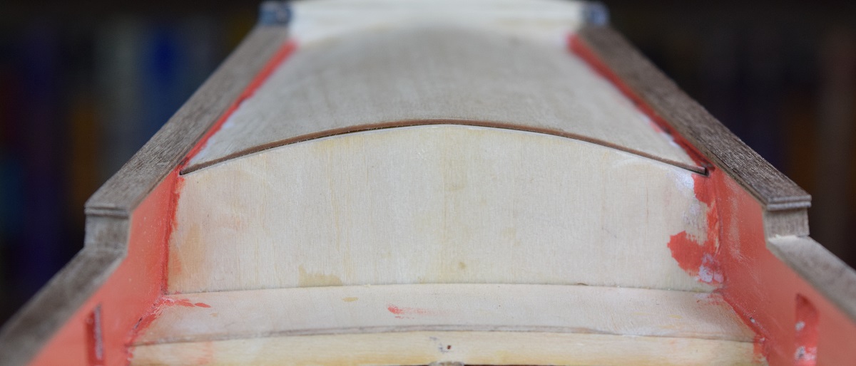 One potential downside of the new camera, it exposes all evils, even when they aren't my fault! Here you can see how much detail (and mess) I can now show by simply cropping out a piece of the 6000x4000 original image. This shows the small 'shim' I had to add at the back of the cap rail - the vertical piece is on top of the shim. I can probably get even closer/better than this by over-riding the camera and shooting manual, but it will take a while to learn the new toy. The wood itself looks pretty rough when zoomed in this close. 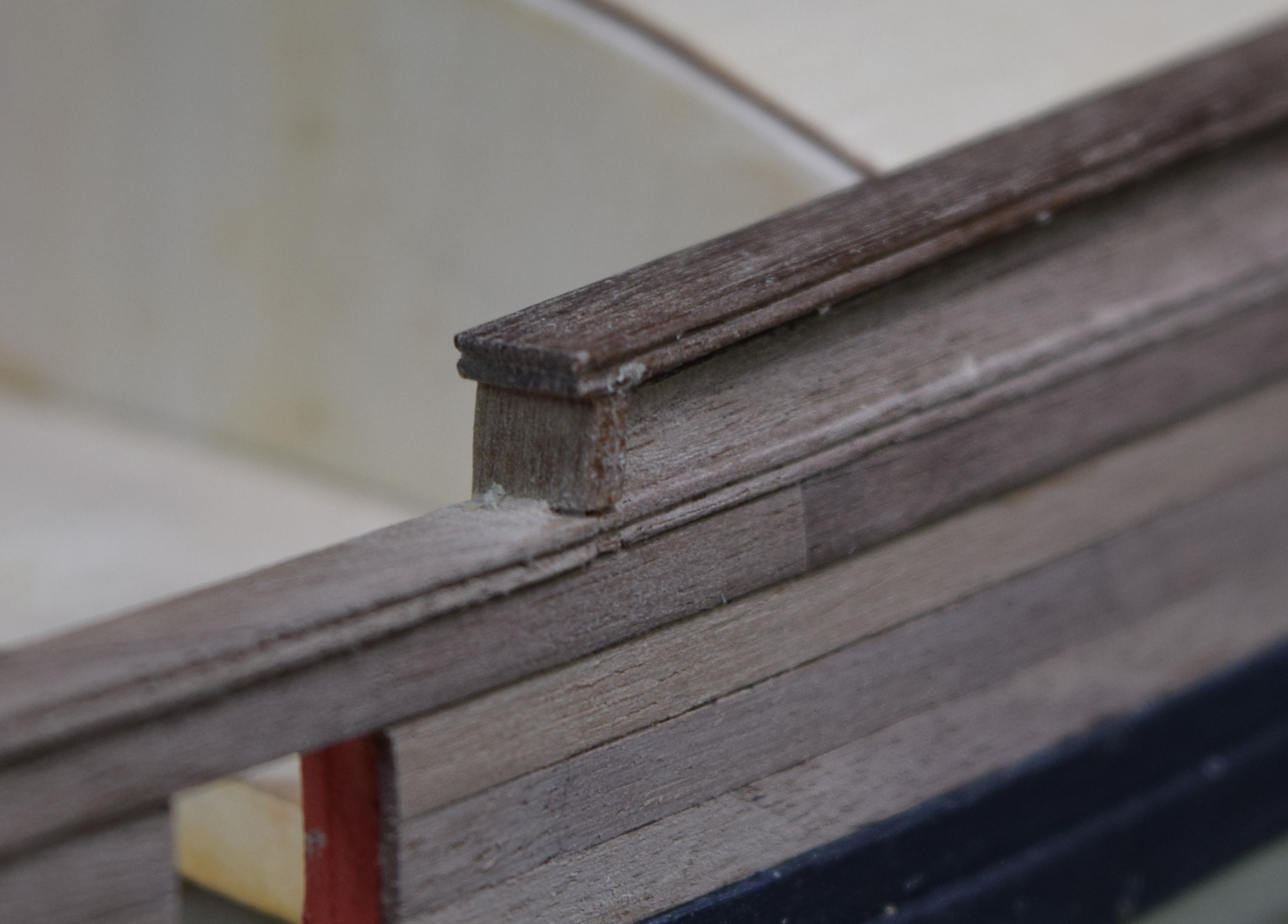 For the stern cap rail, I decided that edge bending the largish walnut just wasn't going to work, so I used some heavy card stock and made a pattern off the top of the stern bulkhead, measured it out to be the same width as the cap rail, and traced it onto the same piece of wood that I made the bow cap rails out of. 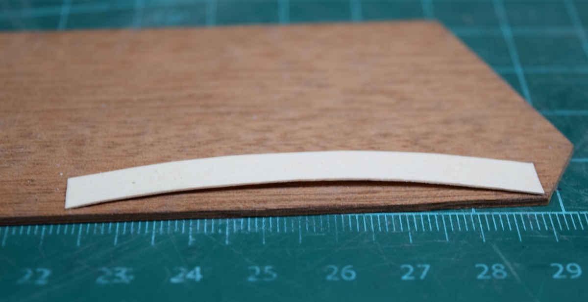 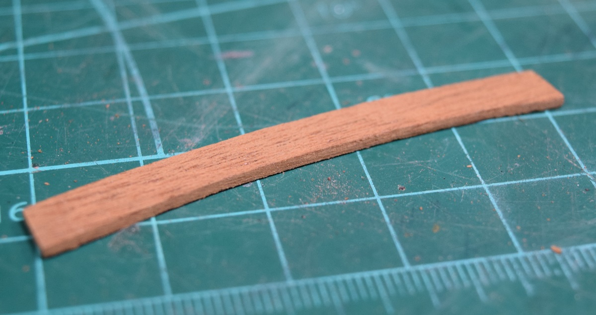 The stern bulkhead was too narrow in comparison with all the other bulkheads, even with an inner layer of planking, and I thought that the cap rail overhang would look too extreme, so I glued a piece of 3/64 basswood to a thick piece of walnut (1/16" instead of the .030) and 'bulked it out', so to speak. 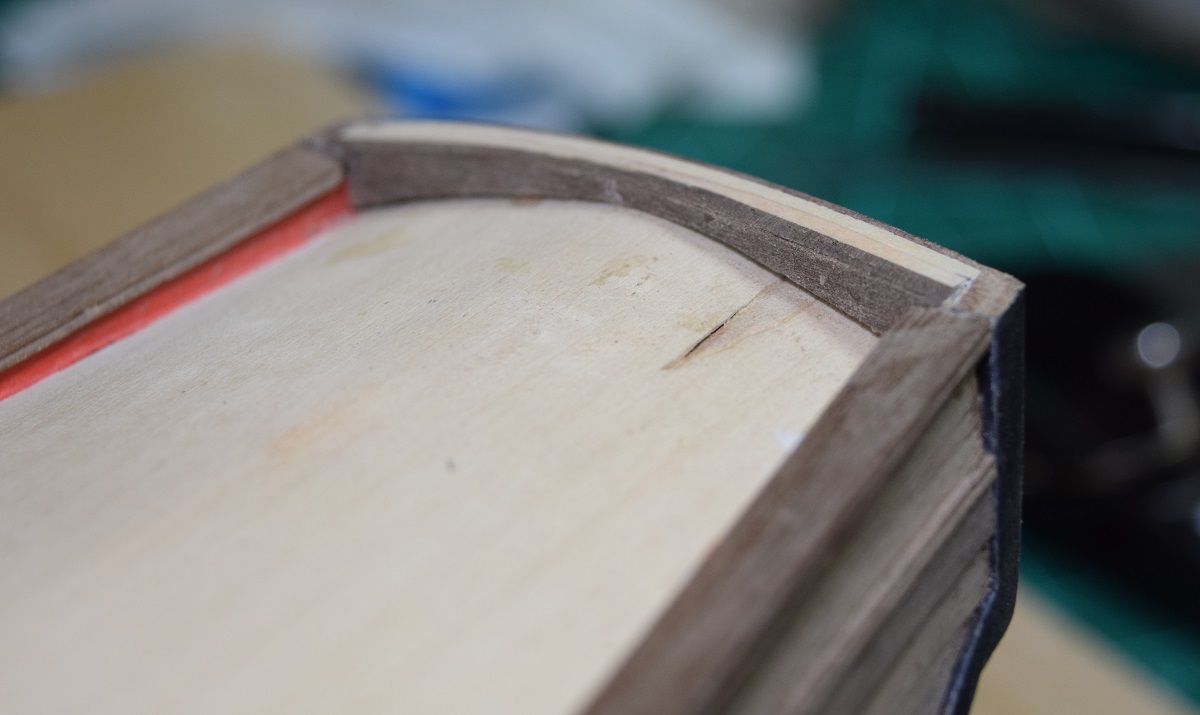 I used a heat gun to pre-bend the new stern cap rail over the curvature of the stern bulkhead (I built a curve into the top, rather than having it flat). This is just laying in place, it's not glued yet, I want to leave it off until I'm done with the tedious priming/sanding/painting process on that bit of inner bulkhead at the stern. Should have done this piece earlier, but I don't think I could have made everything fit right without the cap rails in place so I could see how it all fit together, and trim the stern bulkhead down to the correct height. 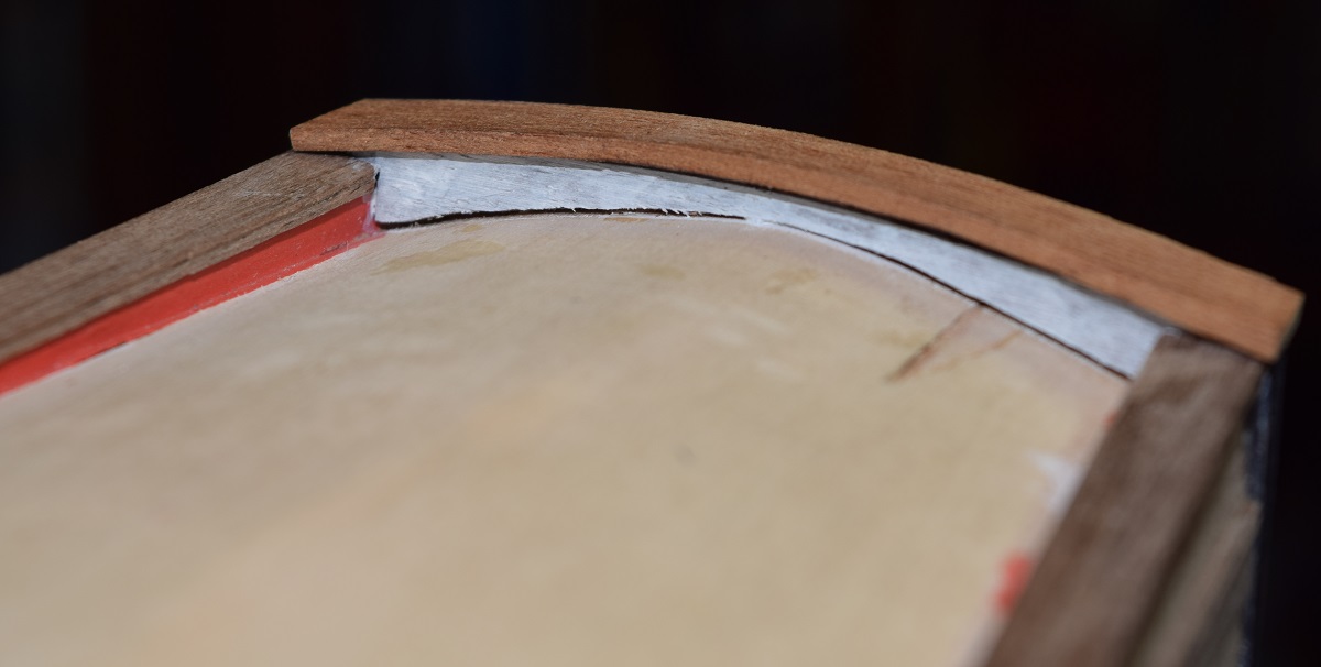 --------------------- I'm working on paint which is of course very time consuming because of the need to wait between coats before sanding and repeating. I did play with the camera a bit this morning, and think that it's going to allow me to take some pretty neat shots later on as I get used to what it can do and how to take advantage of it. This was taken using a tripod with the camera about 6' away from the ship and then cropped. No post-processing done at all, using some natural light from a window and a single LED lamp and the camera flash shut off. 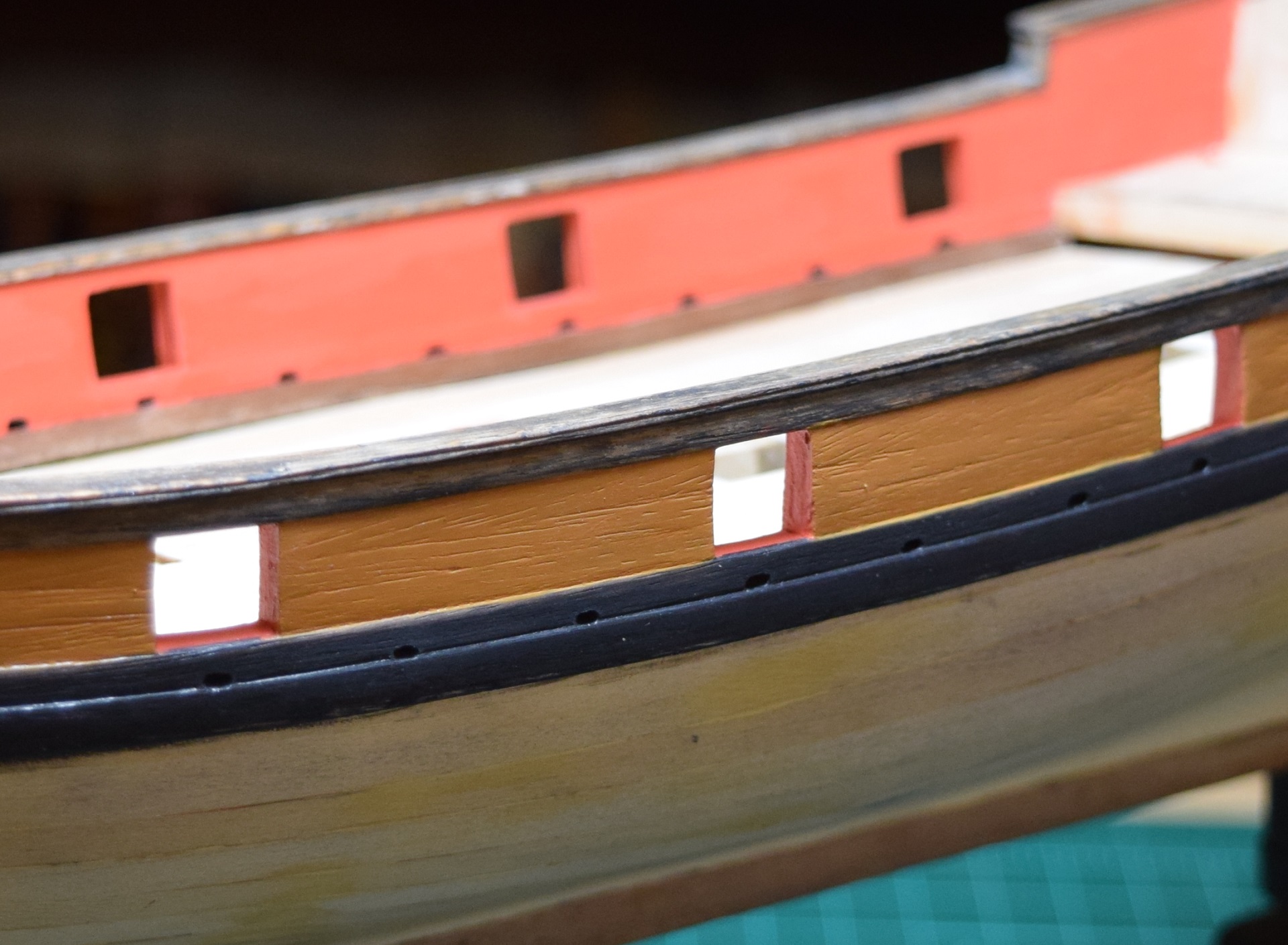 I received a PM from someone this morning who was researching kits for future builds, and he asked about something that's a personal 'beef' of mine - How long is the hull of the AVS? This seems like something that should be made available on all kits by all the manufacturers, yet it's extremely rare in a non-admiralty model to find that measurement. Instead they use the largest measurement they can get, from the tip of the bowsprit to the trailing tip of the gaff boom, and print that on all the literature. While it's nice to know that the AVS will be 31" (787mm) long using that measurement, it really does not give the shopper who is browsing through the kits a very good idea of the real size of the hull, especially when the bowsprit and boom have ridiculously large proportions to the hull like the AVS does. In any case, I figured I would share the measurements here, so that anyone else who is following along and is considering this kit for a future build would have that information as well as the gentleman who asked for this. The hull of the AVS (at least mine!) from the tip of the stem to the back edge of the stern bulkhead is 14 - 27/32" long (377mm for the non-Yanks). That's measured at the top of the cap rail as seen below, so it's the max length, not along the deck to the insides of the bulkheads. 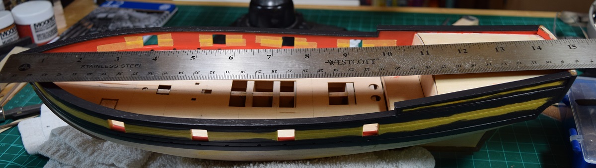 -------------------- So for the last few weeks I've been spending a great deal of time watching paint dry. I may have mentioned in passing (or a lot more than that) that I'm not a terribly patient person, so this has been a fair trial for me. Due to my extremely limited work space I really haven't wanted to jump ahead and work on other bits and pieces because I don't have a reasonable place to put those pieces until they are needed later. Tonight after putting another coat of black on the AVS and setting it back down to dry, I decided that I would look at assembling (but not gluing, so I can put it back in the package) a gun carriage so that I could make sure that it would work height-wise with the gun ports. I am not using the kit carriages, and the ones I am using (from Syren) are taller than the kit ones when looking at just the side pieces, so I was concerned about the fitment. Test fitment was a success, making me really wonder if the kit assemblies would have been too low! The carriages and guns from Chuck (Syren Ship Model Company) are .. well, I'll just let the pictures speak for themselves. 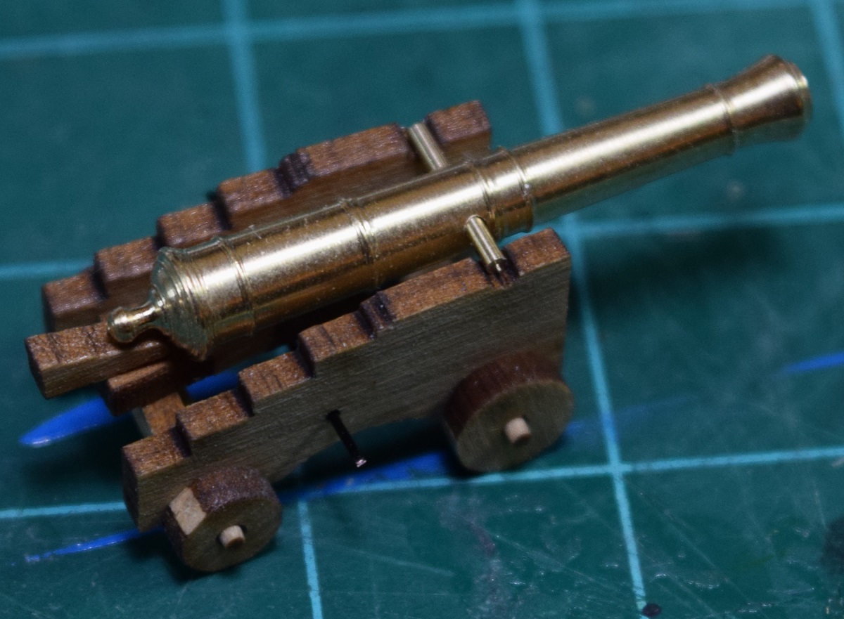 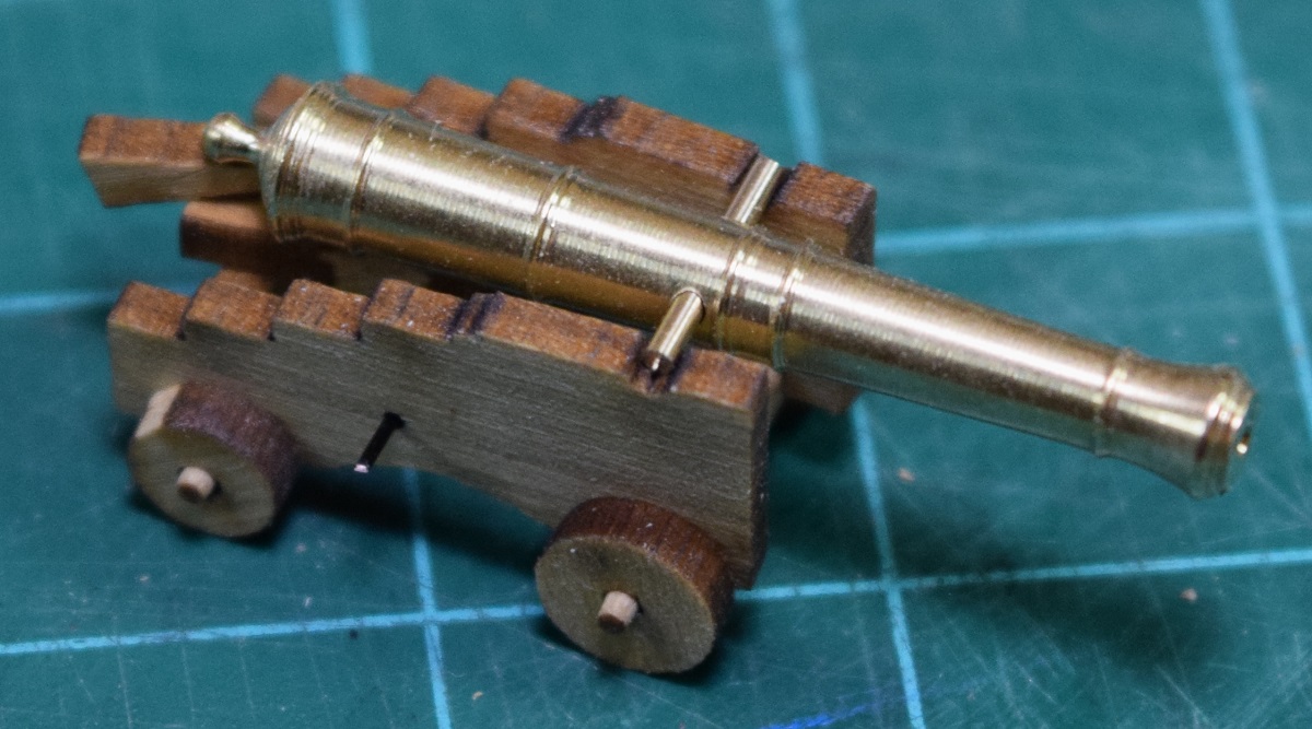 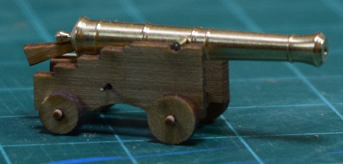 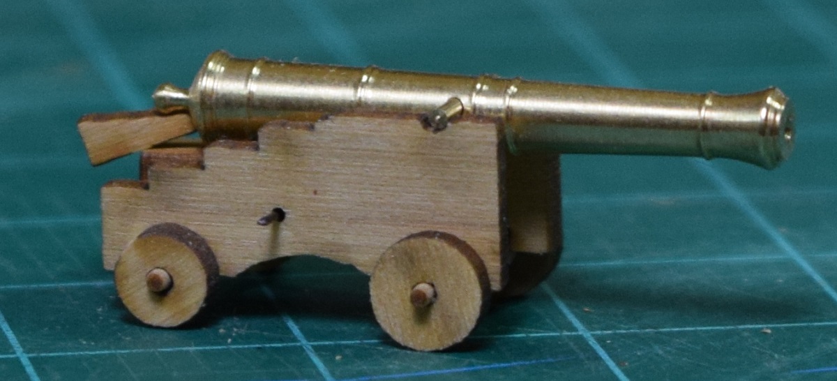 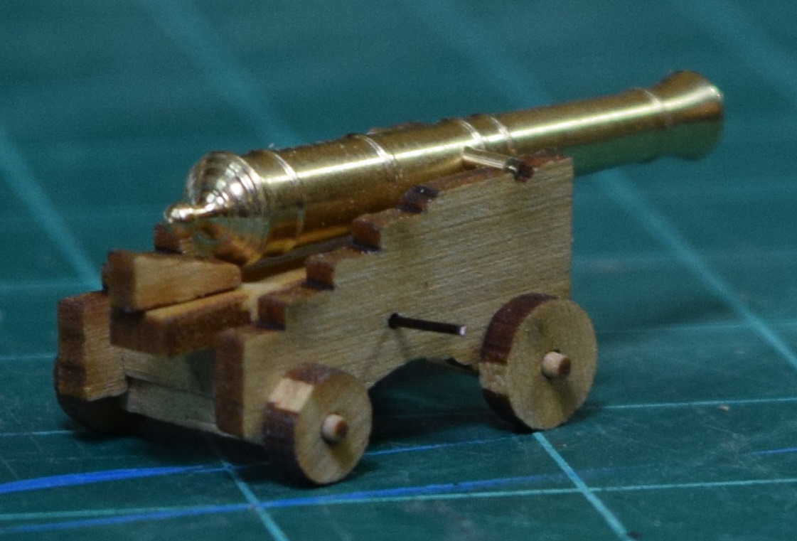 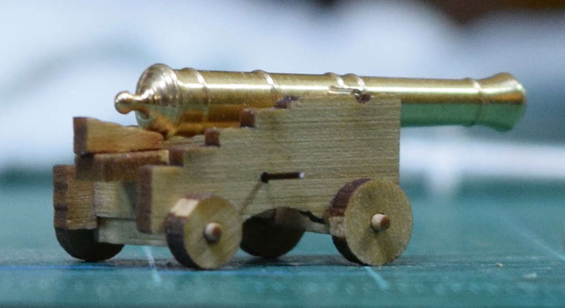 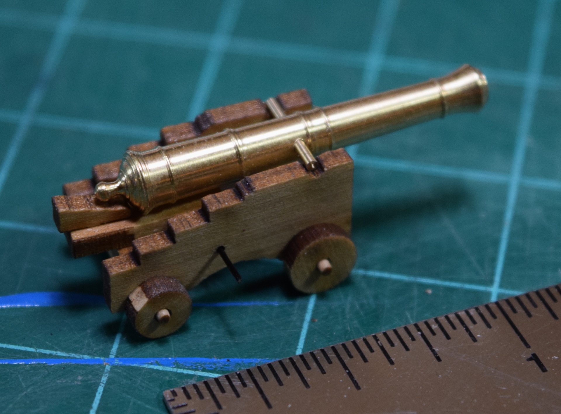 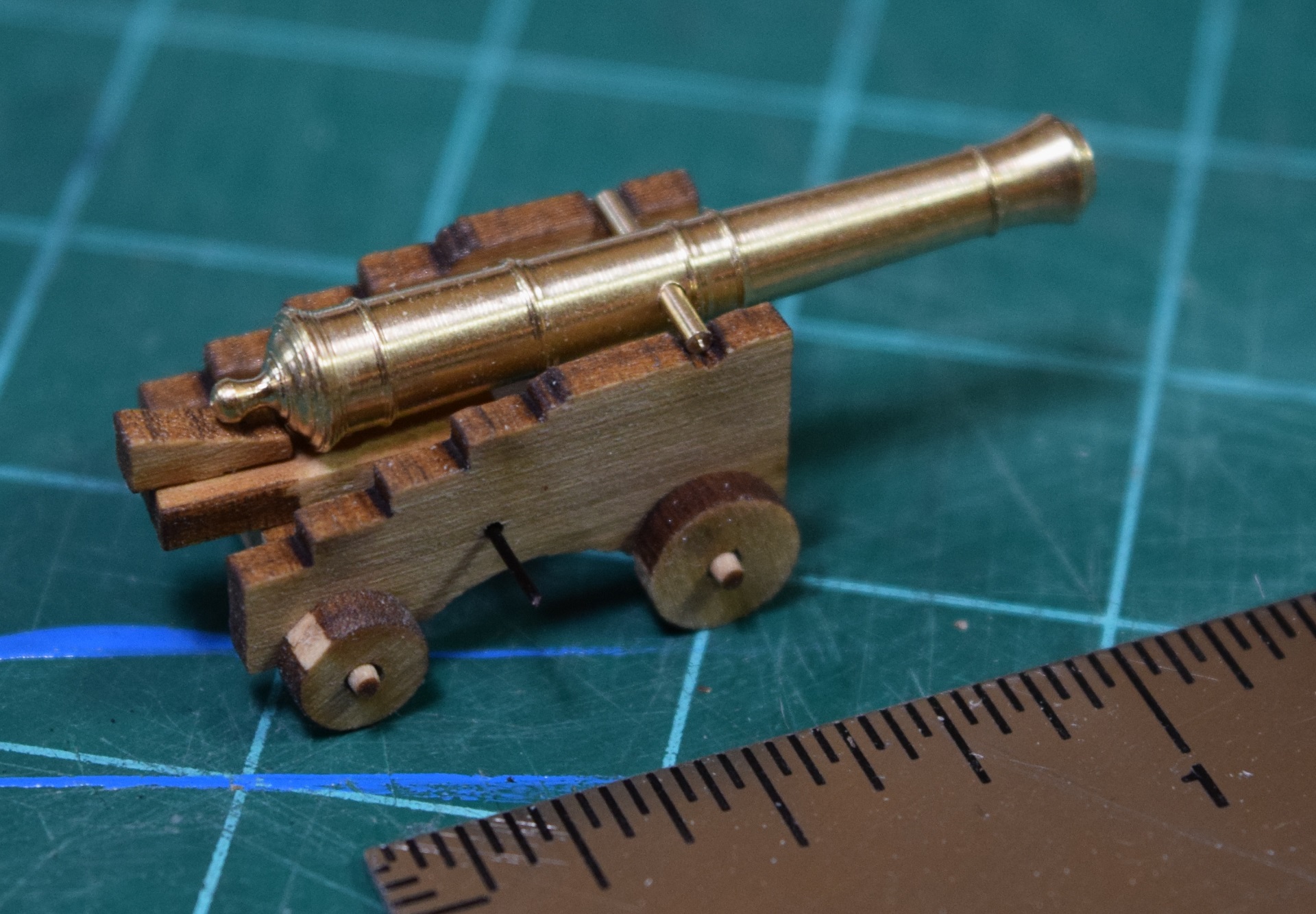 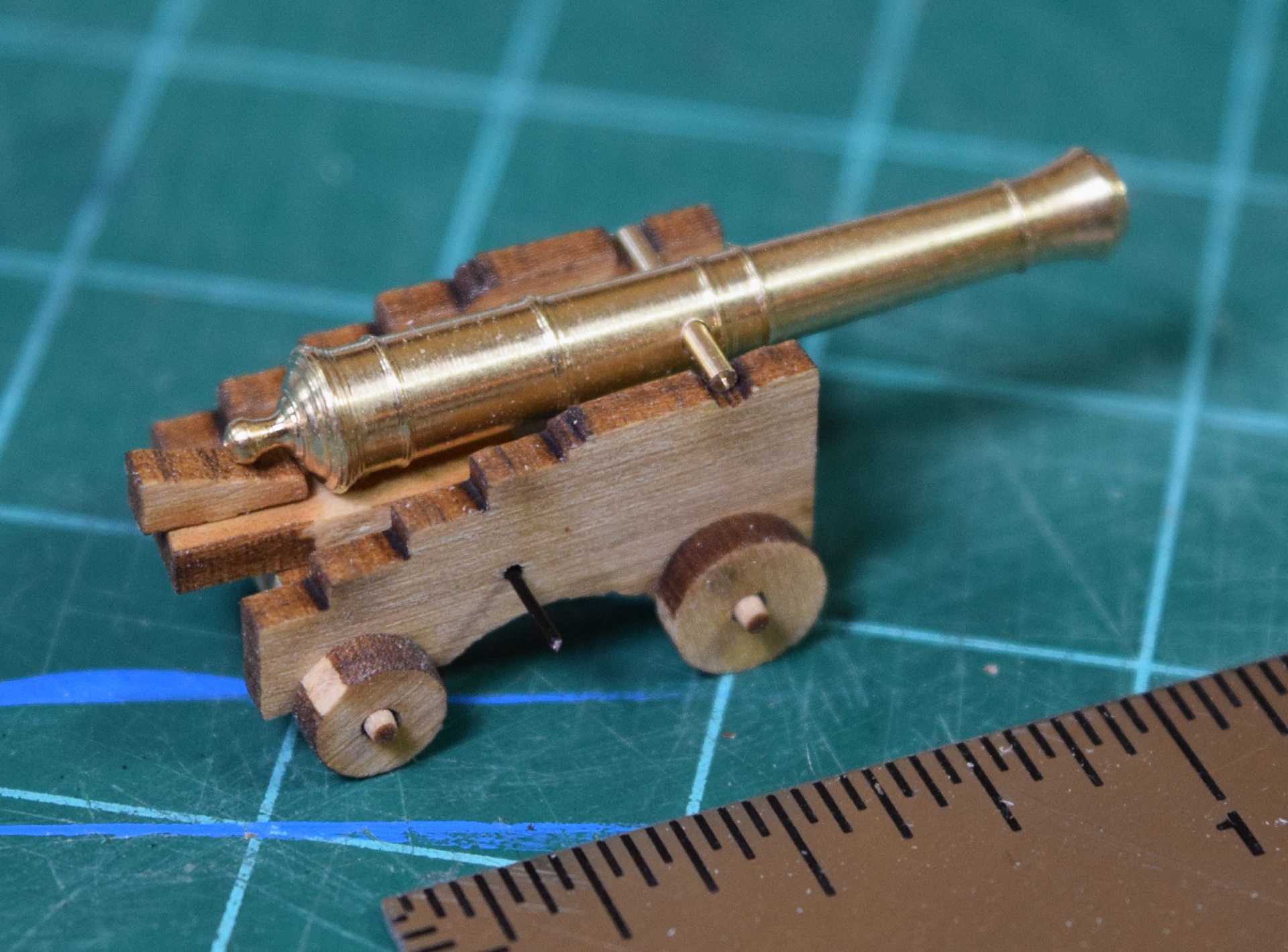 SA log note: I realize that this is a lot of pictures of the same thing, but this was when I was still experimenting with settings and lighting on the new camera so I was including a lot of similar pictures with varied camera/lighting settings. I made a tiny little handle for that tiny little quoin, and then drilled a tiny little hole in the quoin. 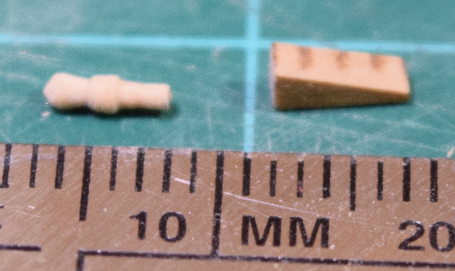 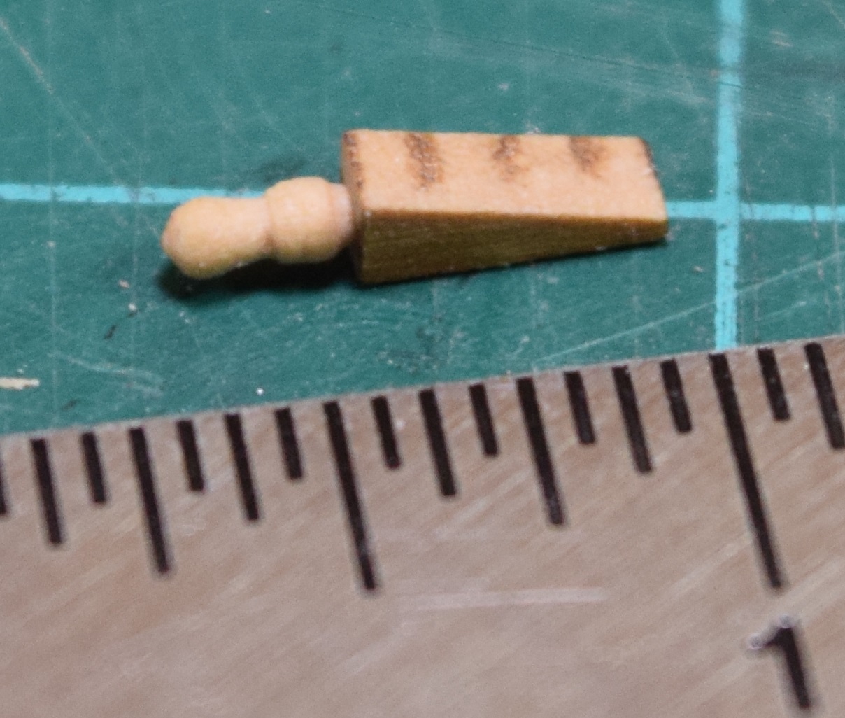 SA log note: The quoin is the angled piece that is shoved under the back of the cannon to control the elevation for range. A comparison of the parts from the AVS kit vs. the aftermarket parts for the cannon. The kit cannon are typical cast white metal, and the carriages are both simpler and 'rougher' and made out of laser cut walnut instead of the aftermarket boxwood. 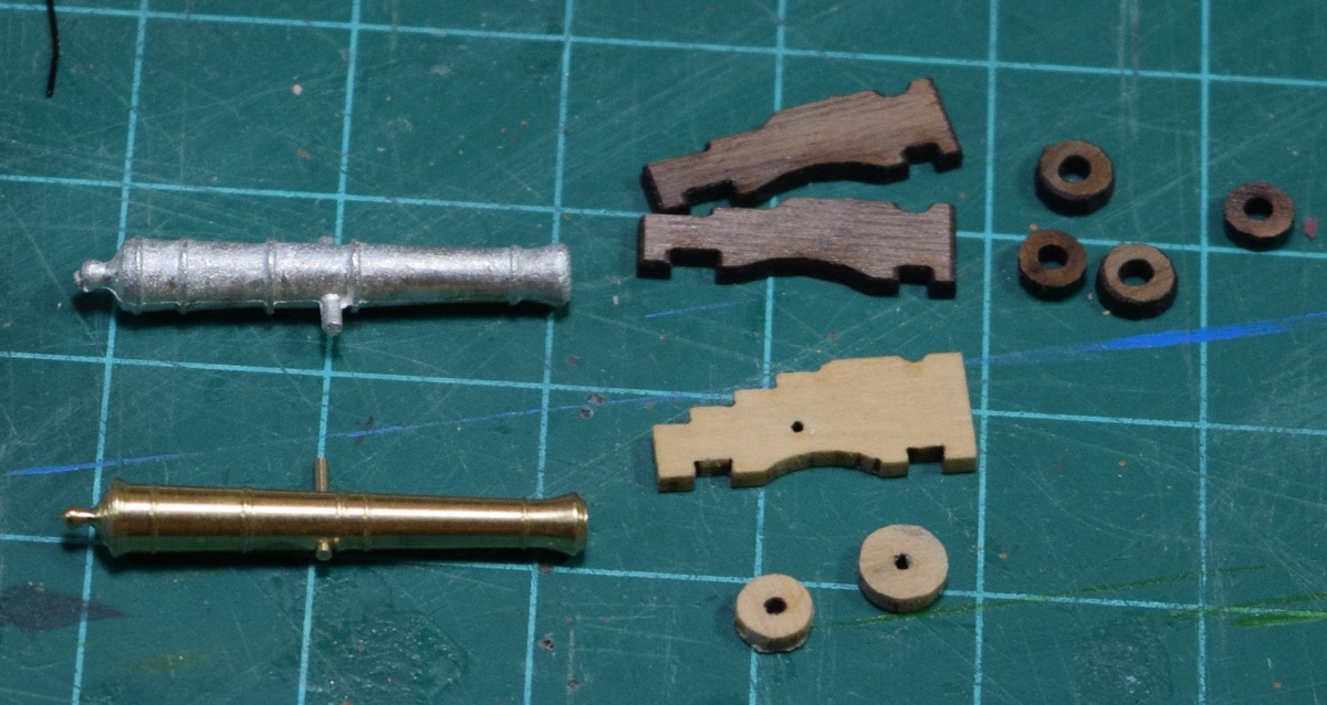 The kit guns are really not bad at all. They are a bit 'fatter' than the brass guns, but are reasonably clean and wouldn't have needed a great deal of clean up. The Syren carriages come with far more parts, everything other than what you see here would have been made from various pieces of walnut (I presume - haven't actually read that part of the instructions) in the kit, rather than getting all of them nicely pre-cut. I'd have had to drill out the barrels in the kit guns as well, as they are only indented slightly. The Syren guns & carriages are actually 1:64 scale 6 pounders, but I printed out the plans from Chucks site at 1:1 scale and laid the kit barrels on top of them before I ordered them, and they are almost identical in length to the kit 4 pounders. So far for the AVS I have (or will) replaced guns, carriages, all rigging and blocks (using kit dead eyes), and have holly for the deck planking. The wale was replaced with boxwood, but that is only because the kit walnut was complete trash. If that walnut had been like all the other walnut in the kit I would have used it I'm sure. I may use some different wood for deck furniture, and I think I'm going to plank the poop (or quarter) deck with cherry instead of walnut, but that's not a sure thing yet either. Construction of this kit was started in late September/Early October, and this installment of the log brings us to December 4th. The Locator fucked around with this message at 02:09 on Oct 28, 2020 |
 #
?
Oct 28, 2020 02:01
#
?
Oct 28, 2020 02:01
|
|


|

|
| # ? Apr 26, 2024 05:35 |
|
|
Cessna posted:This is so cool. I've always wanted to build a wooden ship model, but know I'd get all tangled up with the string and knots and such. See, for me, it's the rigging I want to do the most. The planking is the part that's really prevented me from starting.
|
|
#
?
Oct 28, 2020 11:26
|
|

|
So I decided that good is good enough, and I'm tired of painting black layers. So, I decided tonight would be the night for the 'big reveal'. How well did my masking work? Was all of this a huge waste of time because the black bled all over the yellow ochre? (insert drum roll here) 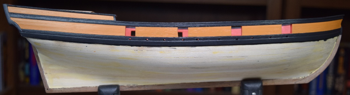 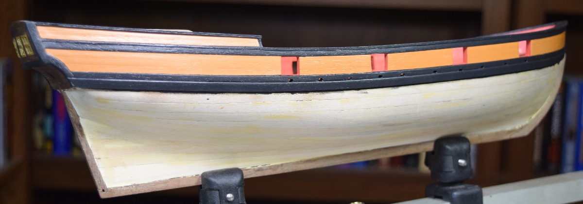 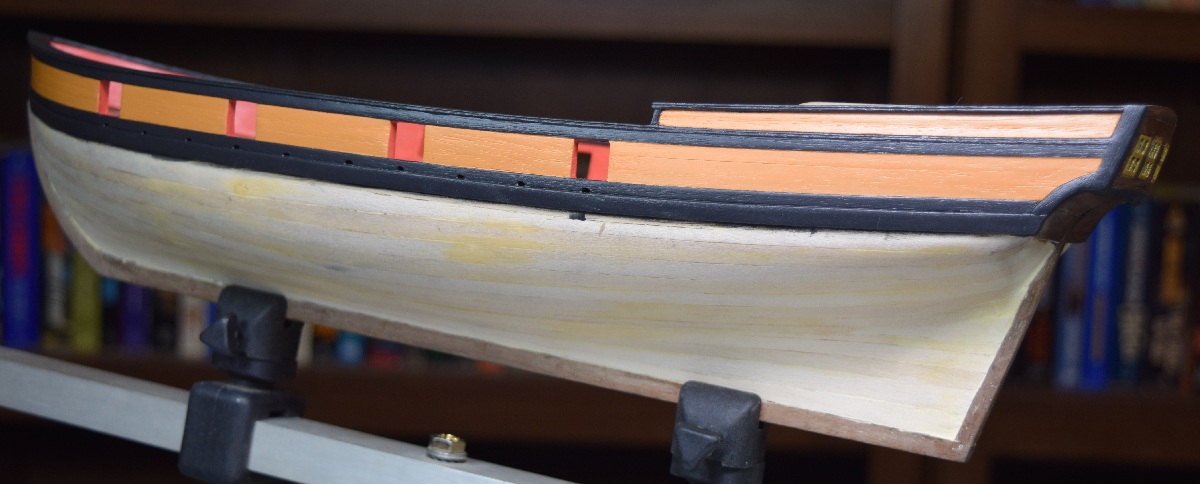 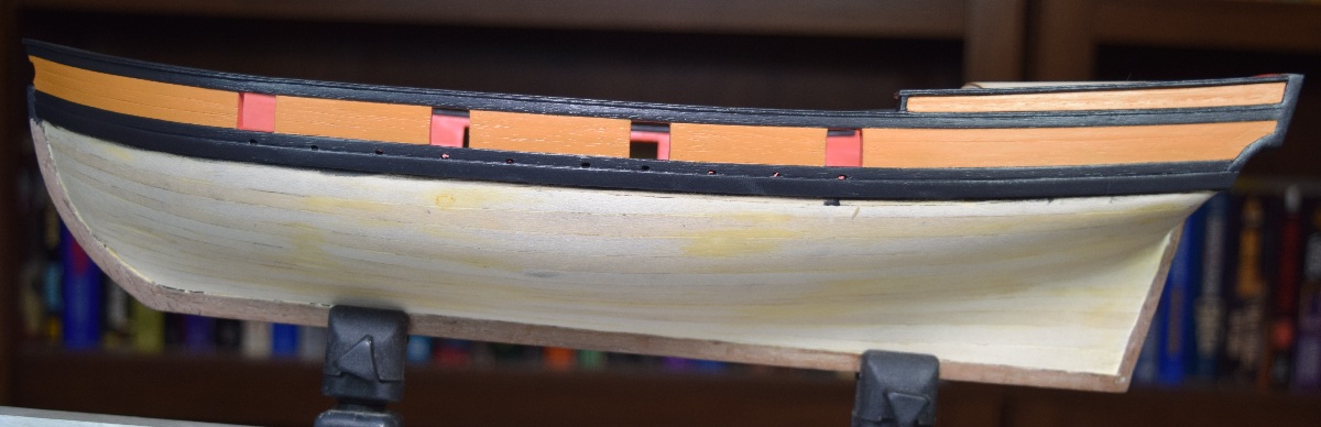 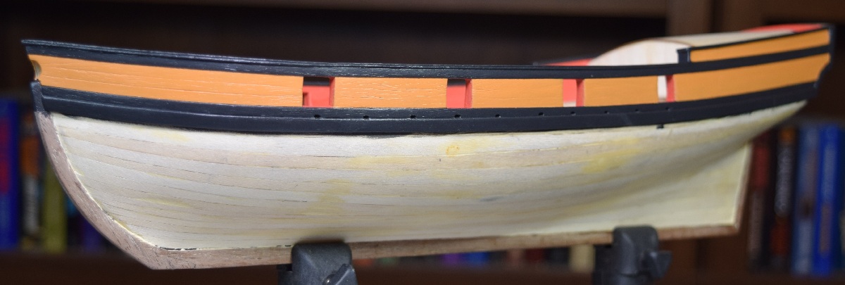 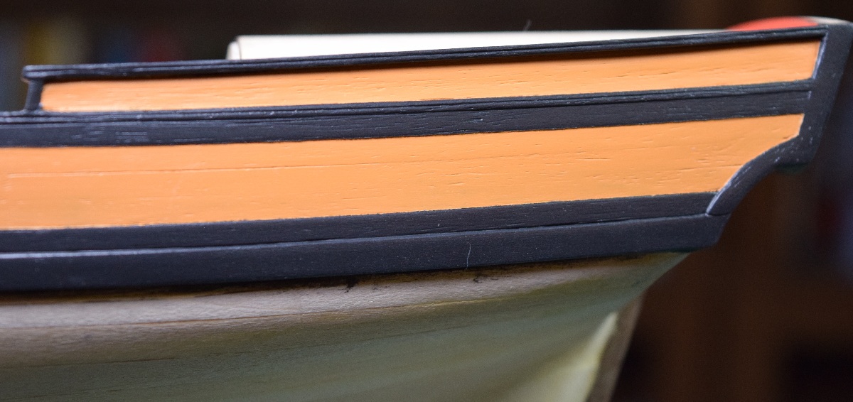 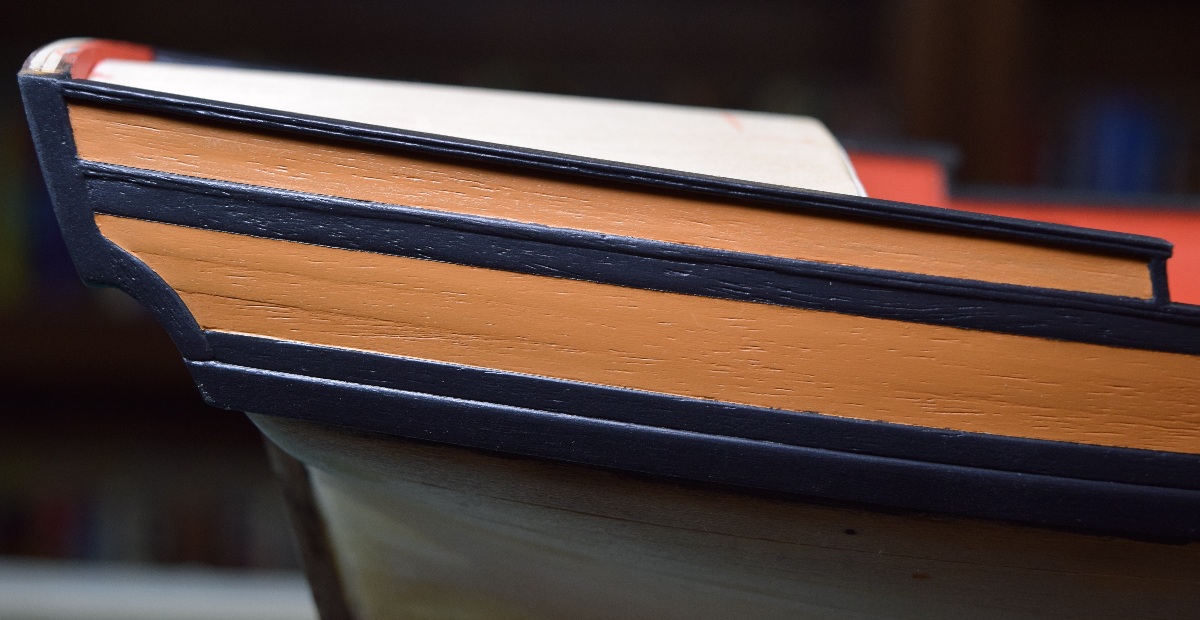 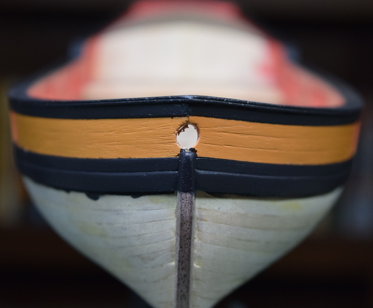 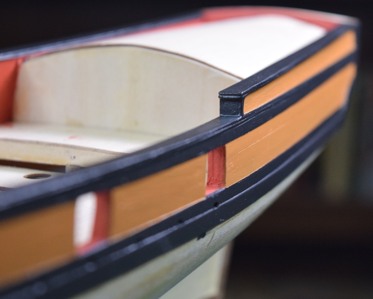 I can live with this. This is prior to buffing (not fully dry on the final coat of black) and adding a couple layers of clear poly. Needs a bit of touch up here and there, especially in the bottom and top of the gun ports, but certainly a paint job I can live with for my first run at wood painting. As far as colors go, I painted 4 different color strips (3 different blues and a green) and laid them up against the hull to eyeball, and while the blue certainly adds a nice splash of color, I think I'm going to be different from every other AVS build I've seen, and leave the sheer strake black. In the instruction manual, painting the sheer strake blue, red, or green is 'optional', and I'm kind of fond of the black right now. Tomorrow I can put the taffrail on, and then apply a couple coats of poly to protect the paint, then it's time to start the 2nd planking of the hull!  -------------------- Let the second planking begin! 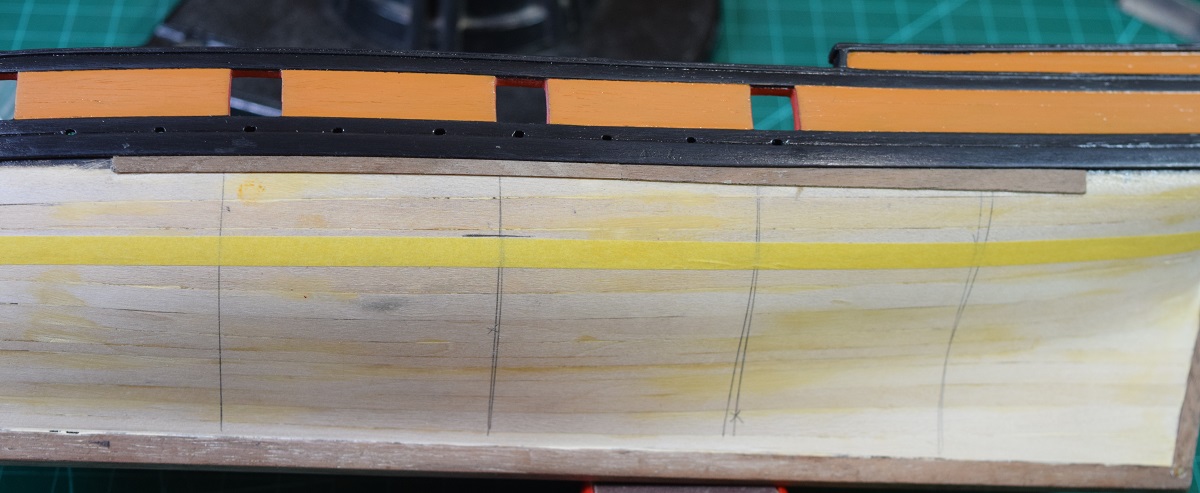 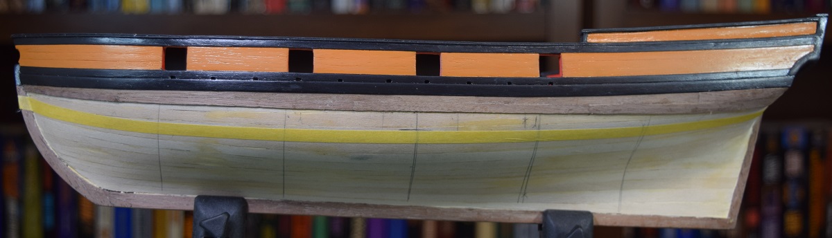 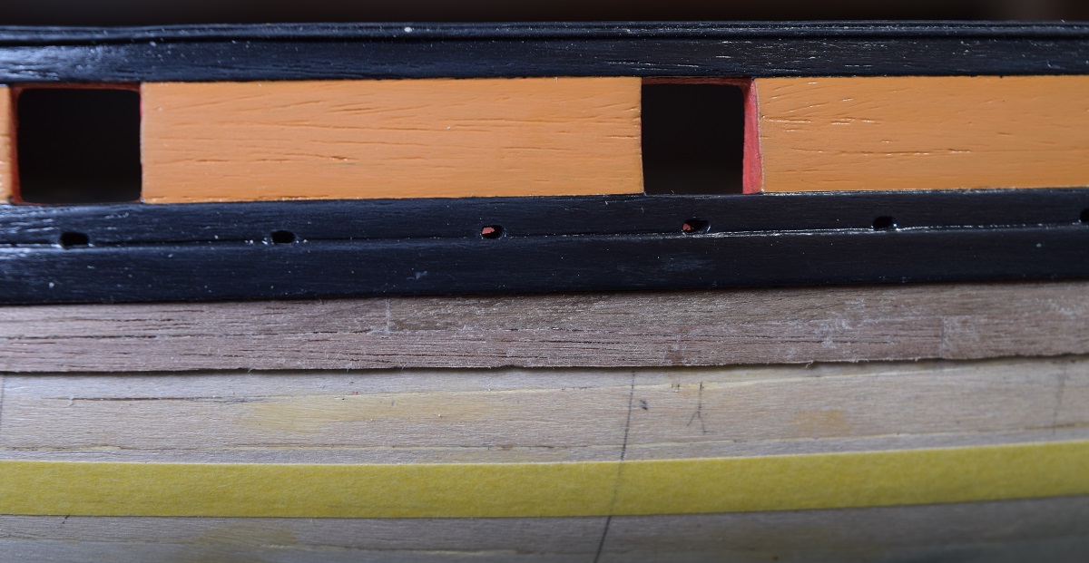 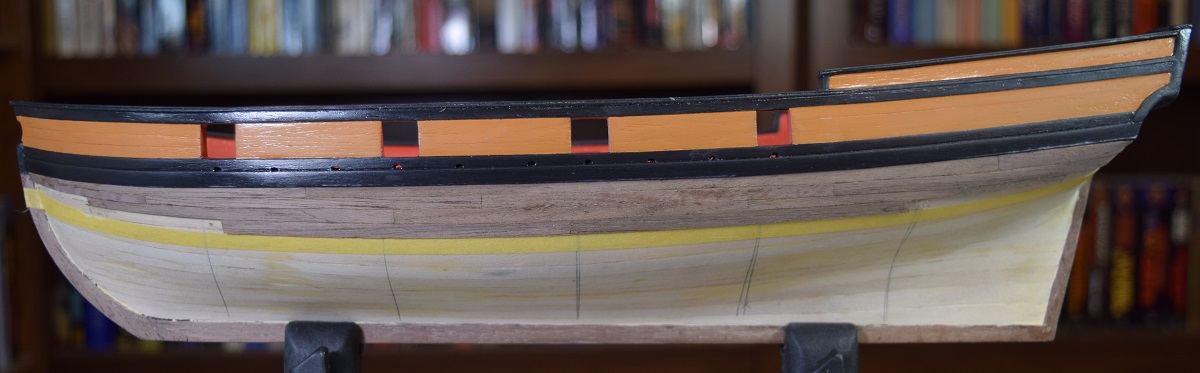 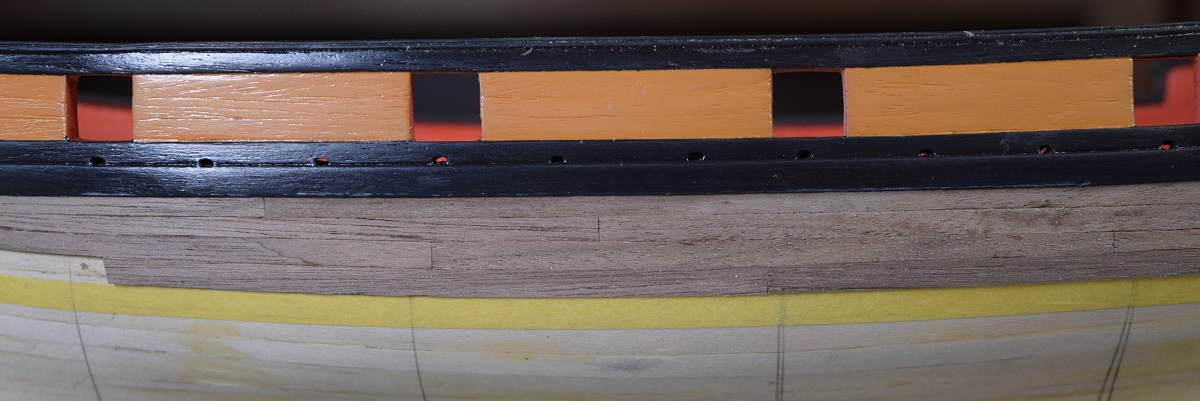 So far done completely with PVA (Titebond Original wood glue) glue and no clamps, just holding each plank in position until the PVA takes enough set to hold it. We'll see how far along I get with this system. For the stern, I've only gotten two of the planks wrapped to the transom so far, and I've used water and heat to get them into shape prior to gluing. Hopefully will be able to continue to get the shape of the planks at the stern very close to shape before placing. If not I'll likely have to resort to clamps at some point. The first group of planking (of 4 planned sections) is complete on both sides, and the 2nd group is started on the port side. As I was cropping these pictures I realized how much damage I'm managing to inflict on my poor painted cap rails, so I'm going to need to do a lot of repainting when I'm done with all the heavy handling of the hull. In the meantime I'm going to cover the rails with tape to try to prevent further damage, since I'm apparently incapable of doing work on the hull and not beating up the already completed work. 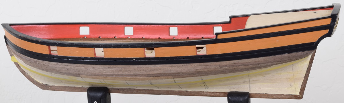 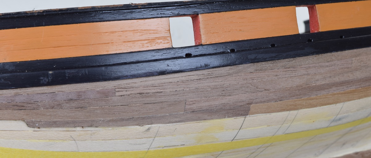 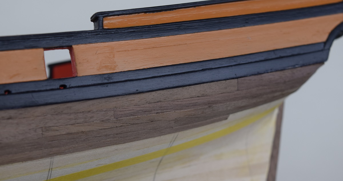 SA Log notes: The process of determining just what width each plank should be, at each point on the hull, and the pattern of the planks is a subject that occupies a large amount of space on shipbuilding forums. I'll try to give a simple explanation, and if anyone has questions let me know and I'll do my best to explain. Step 1 is to measure the length from the keel up to the wales (black strip) at a bunch of different points until the longest measurement is found. Using that measurement you can figure out how many planks you need based on the width of your planking material. Step 2 is to make a bunch of vertical 'lines' on the hull at various points. You can see a fair number of these in the photos. Then, using a reasonably stiff paper (I used manila folders) you cut a small strip of paper to the length of that line. Step 3 is to place that strip of paper on a drawing (PDF printed out) called a planking fan. It's just a bunch of lines that start out far apart at one end of the paper and converge to a single point a the other end. You move the strip of paper along the 'fan' until you find a point where the number of planks fits onto that paper strip, and then transfer the lines as marks to your paper. This gives you a 'tic strip' - i.e. a piece of paper with 'tic marks' on it. Step 4 is to transfer those marks to the hull along the line you cut the paper strip to fit. Step 5 repeat this with all your other lines until you have tic marks all along the length of the hull on each vertical line. Those are now your planking width guides at each point on the hull. Step 6 Divide the hull into 3 or 4 'sections' depending on how big the hull is. Each section should be around 4-6 plank widths usually. This is just to make the area you are currently working on manageable. This is what the tape in the pictures is for, showing the edge of the current work area. Step 7 Decide on your scale plank length and make a bunch of planks about that length. I go into that later in the log. For purely appearance reasons I went with a 16' scale plank length, which is 4" long on the model. In reality in this era the planks would have been quite a bit longer probably, in the 25'+ range, but I wanted to actually be able to see the planking pattern in the finished model. As large trees suitable for planking got rarer, the planking length and width both got smaller. Step 8 Pick a spot and start planking! Each plank has to be shaped via sanding or cutting to fit within the 'tic marks' for that section of hull. Almost no planks on a ship model are the same width at both ends and the middle. Test fitting is important. Once the size is correct, the edge of the plank that will be going up against an already placed plank gets a reverse bevel to allow tight fitment when the plank is placed on the curve of the hull.
|
|
#
?
Oct 28, 2020 23:48
|
|
|
Planking progresses. Band 1 on the starboard side complete, band 1 and 2 on port side complete now, so 3 of 8 done. I'm liking the way it's coming together. As long as I don't make a massive mistake at some point along the line I fully expect to leave the hull below the wale natural. I may do something with the waterline (paint line) but still undecided at this point, not sure if it would look good or terrible with the natural above and below it. Still using just PVA, but I am using pins with collars to temporarily clamp some of the planks at the stem and stern to help me hold the trickier ones in place while the glue sets. Getting the curves mostly set into the planks using a heat gun makes things go pretty smoothly for the most part. I do need to figure out how to open up the rabbet a bit before laying the garboard strake, as I currently can't get the thickness of a plank into it along the keel, and I need to get these planks flush. Combination of sanding blocks and filing I imagine, but I've got band 2 on the starboard side to complete while I ponder that. 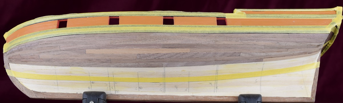 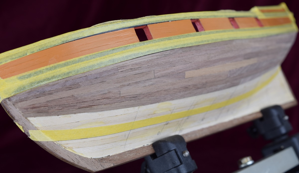 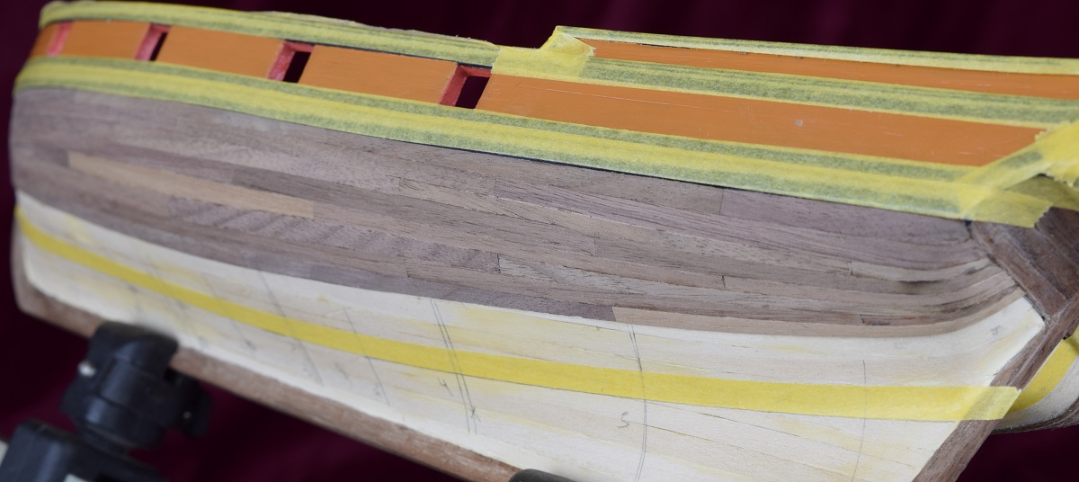 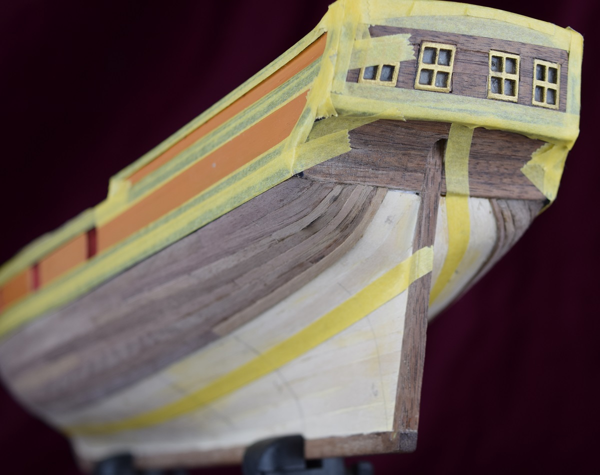 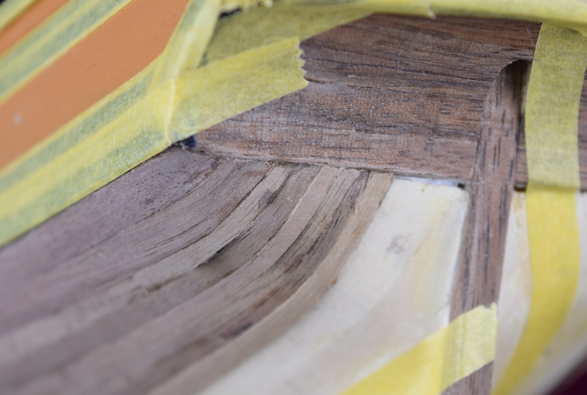 Still not completely happy with how the planks meet the transom, but can't think of any way to improve it at this time. I'm thinking that it would look better with wider strakes landing on the transom, but I'm not going to deconstruct half the planking in order to add the drop planks needed to get wider strakes to it at this point. ------------------ Less done than I would have liked in the last couple days, but finished the 2nd band of planking tonight. The pictures make the bow look more out of symmetry than the stern, but when measured the bow is actually within 1mm of even, and the stern is off by about 2x that much. I think it will blend in with how narrow the planks are where they bend over the transom, but I'll try to get it adjusted across the next few planks. 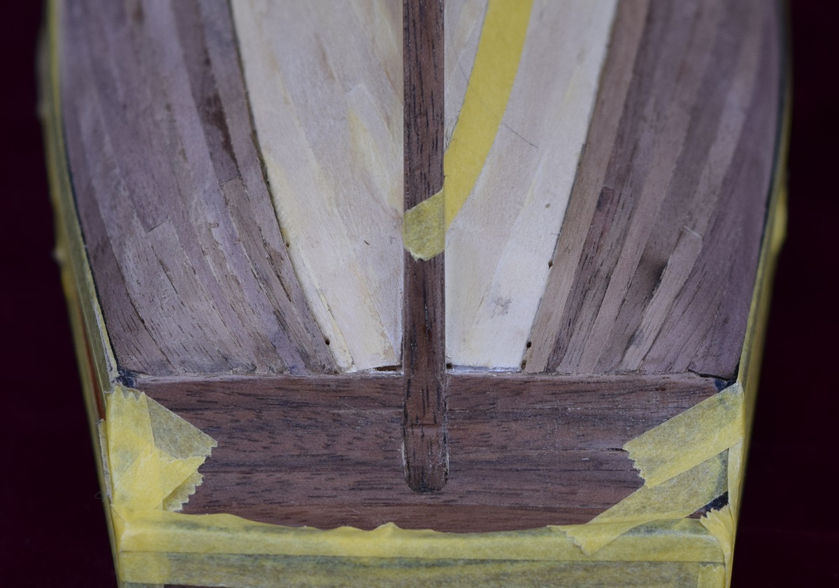 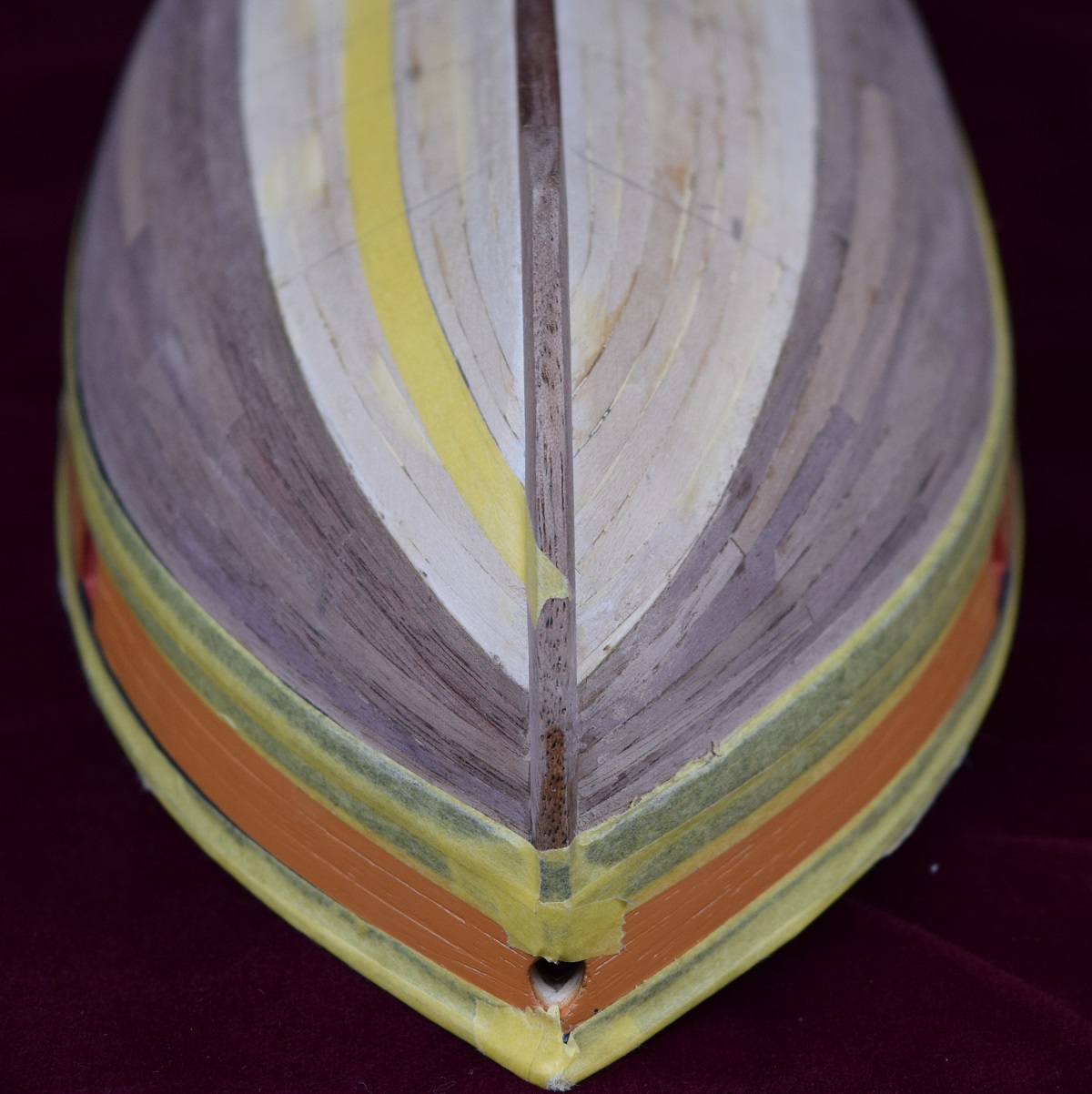 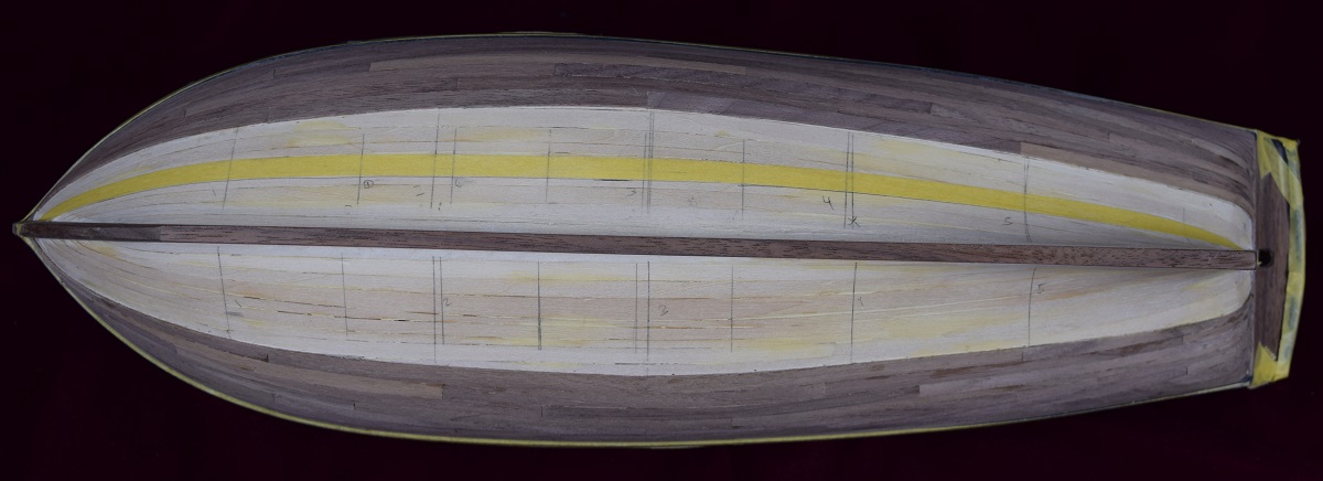 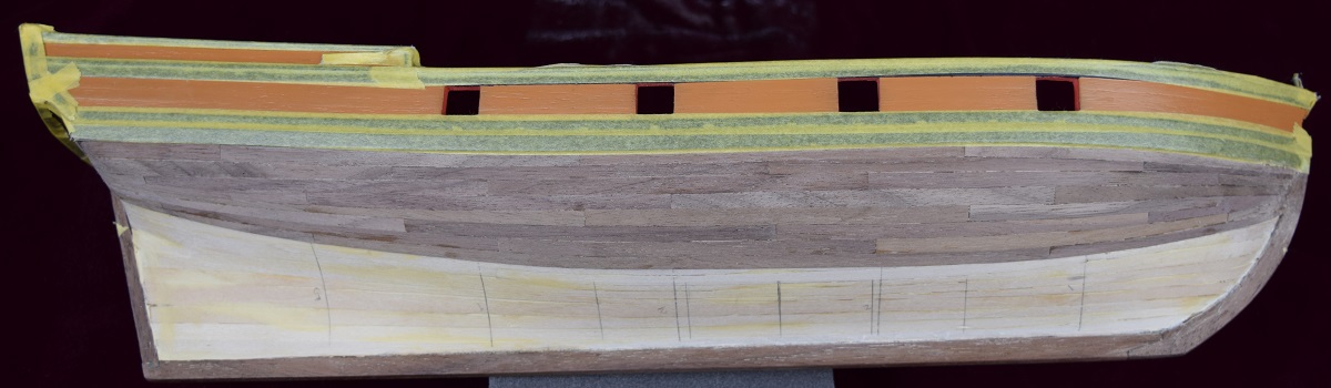 ---------------- Off topic update. Not much has changed on the AVS, as I have spent very little time on it during the holidays so far, been crazy busy with lots of other stuff. One of the big 'other stuff' is the progress on a dedicated ship-building room. Up until now I've been doing all my work on a single Harbor Freight workbench in my library/office/computer room. 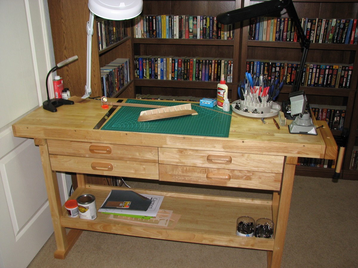 Ever since I moved into my house I've just used the front bedroom as storage, so over the last couple of months I've cleaned it out of all the stacks of boxes that remain unopened from my last move 10 years ago, until it was nothing but a bare carpeted bedroom. Then, I ripped out the old, but never used carpeting, because everyone who makes scale models knows that the carpet-monster is the eater of small parts, and put in a light colored (maple) hardwood floor to turn this room into a dedicated modeling space. For Christmas my brother bought me another Harbor Freight bench, so I now have double the workbench space and an entire room to fill with stuff I don't really need! Still a lot of stuff to move, and will take a while to figure out where I want to put everything, but I'm up and running for doing work again! 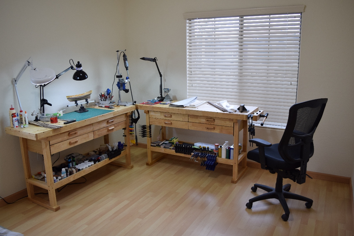 I have a lot more planned for this room, adding shelving and a lot more countertop and storage, but that will come over time. On the ship building side of things.. ship building update! I finished the lower band of planking on the port side of the AVS. 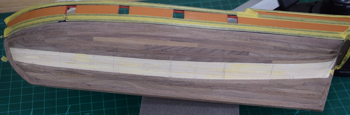 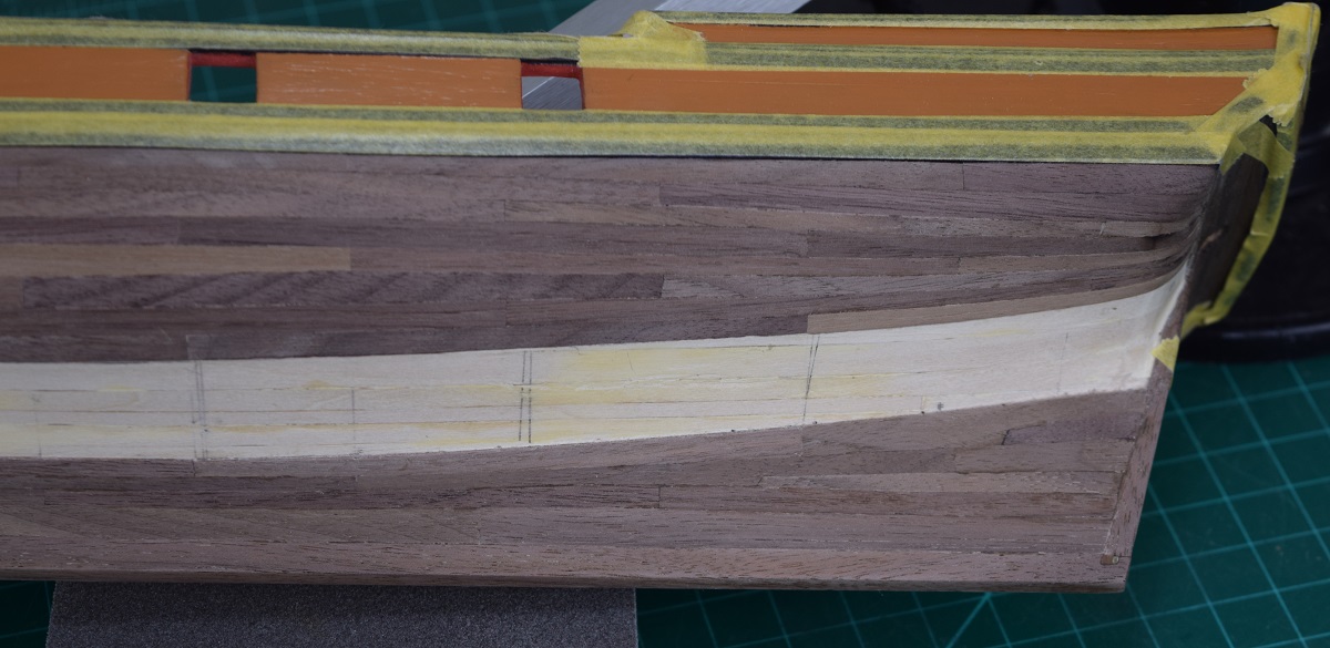 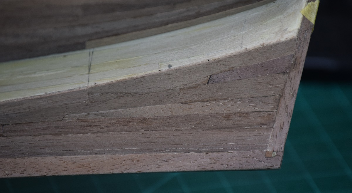 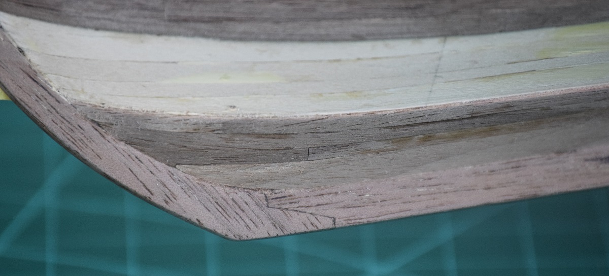 I'm pretty annoyed at that last stealer. When I placed it the fitment was absolutely perfect, and the piece would just barely fit into the spot for it, yet after letting it dry and removing the clamp.. there is a big ol' gap there (not terribly apparent in 'life', but the macro shot sure shows it up ugly as can be).  I'll do some sanding/white glue fill and hopefully it will cover it up pretty well.
|
|
#
?
Oct 29, 2020 22:33
|
|
|
Started working on the lower band of planking on the starboard side, got the garboard strake plus the next one in...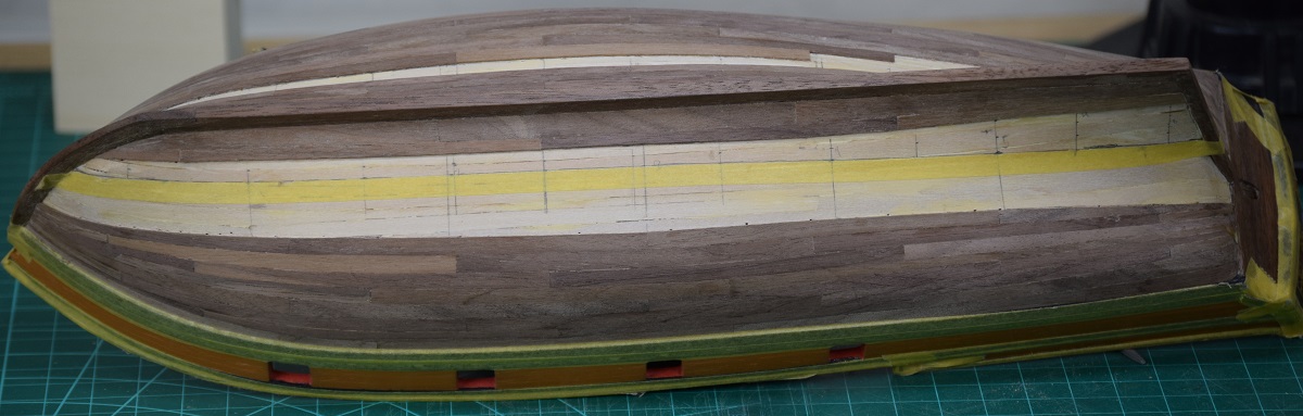 And worked on the final band of planking on the port side... 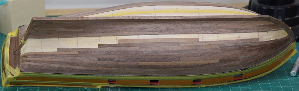 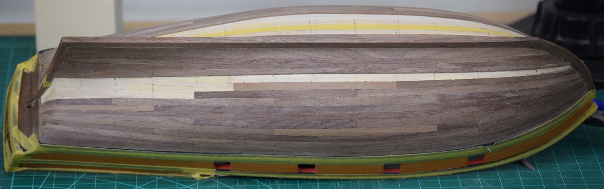 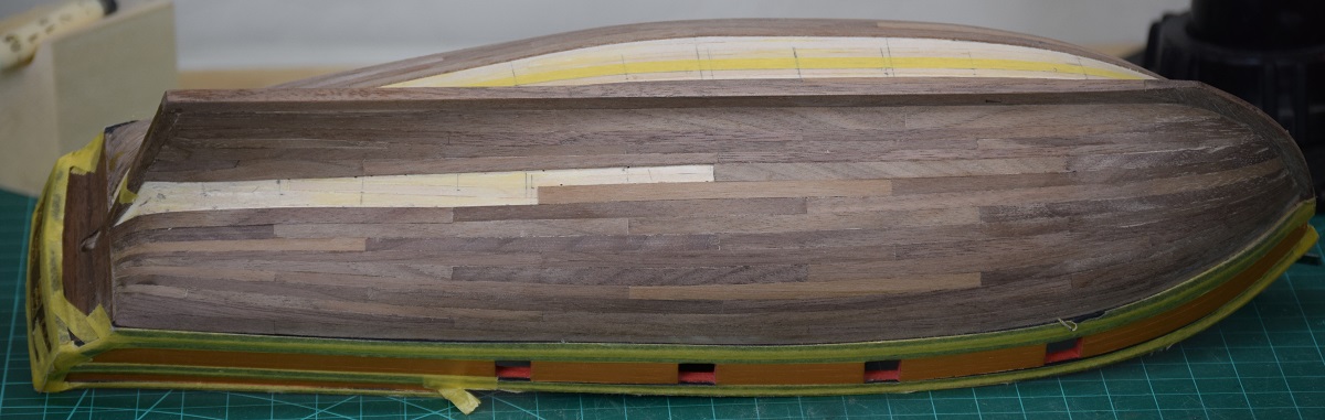 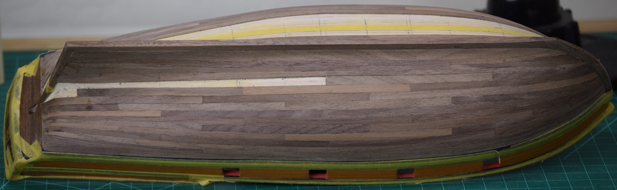 Last plank on the port side! 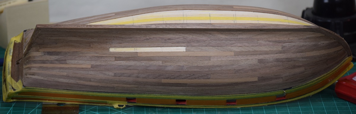 And the final plank glued in place... 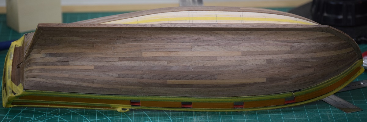 And then cleaned it up with a damp cloth for a few photo's. 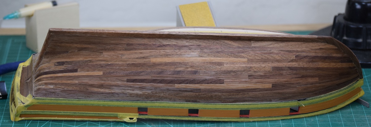 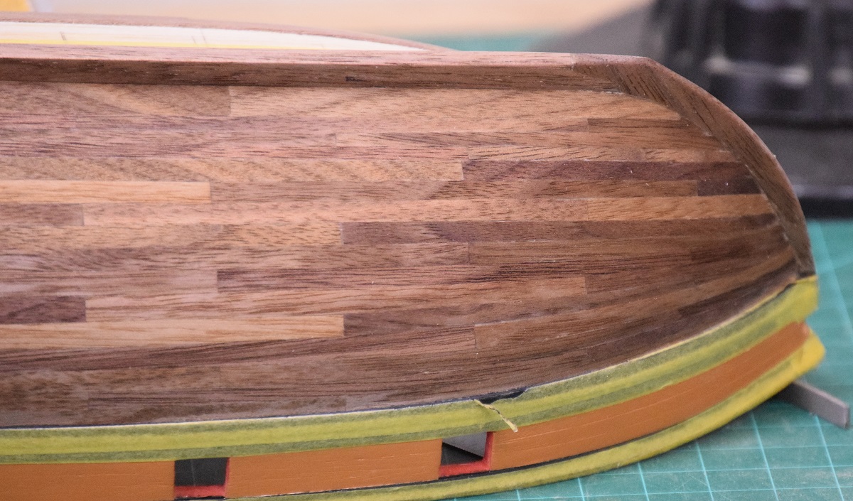 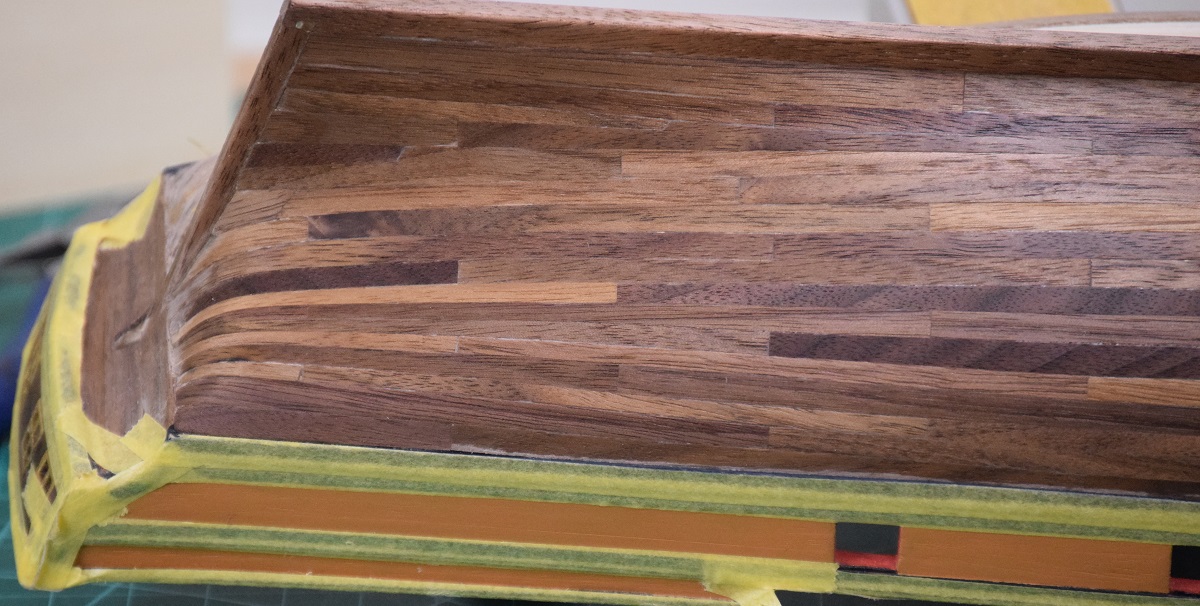 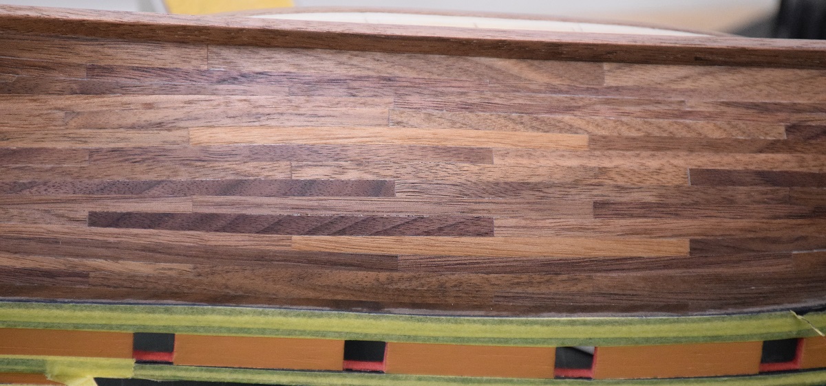 I made a number of mistakes on the planking, and I'm sure the eagle eyed amongst you can spot at least a couple of them, but outside of the ship-building community, I doubt anyone will notice, and the overall effect is quite nice, and I think it will really look nice after some final sanding and coating with poly. Hopefully I can finish up the planking and get a coat of poly on it by next weekend, then I can finally move on to other stuff (and re-mask and paint the black that I damaged while planking before I covered it with tape). I decided to try something with the final band, and while it didn't come out perfectly, some people might find it interesting. I made a time-lapse of the planking. First attempt at any sort of time-lapse stuff, and I didn't get the positioning exact between shots, and I'm far too lazy to properly crop this and do positioning in post.  It has music just for fill, you won't miss anything if you mute it. The video does show most of the planks just laying on the hull prior to clamping in place, so it shows how each is uniquely shaped and bent/curved for a specific spot. https://www.youtube.com/watch?v=AqE9S72i8Uc Random picture of plank clamping not included in the original build log that I can see, maybe I used it later! 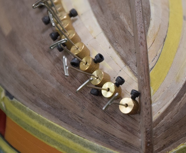 The video was kind of fun, but I don't think I'll do more of that, as stopping to get the photo between every little step is sort of annoying, and the result really isn't as cool as I was hoping for since even though I had the tripod location marked on the floor, and the hull location taped off on the bench, there was still quite a bit of movement between shots. I'm sure that could be adjusted in post by careful cropping, but I'm not a post-processing guru by any stretch, and the time and effort to learn how to do that wasn't something I was willing to do for this. SA Note: In response to a question on the log about whether the planks were 'spiled', which is the process of cutting each plank from a larger piece of wood: As far a spiling, I guess it depends on how you define that word. The planks aren't truly spiled, in the sense that they are not individually cut from wider stock in a curved shape like true spiling. I used the kit .030 supplied planks strips. I'll see if I can describe my system. First, the hull was done in 4 'bands' which are approximately 4 planks wide at the widest point (not counting the stern). After masking off the band with tape, I used card stock (manila folders) cut into narrow strips and used the cards to transfer tick-marks from a planking fan to give myself a bunch of reference points for the plank widths needed at various spots along the hull. Here is a zoomed in image which corresponds to the first image in the video showing part of the middle section of the final band marked off. 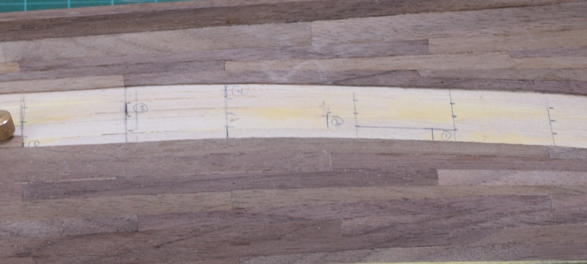 You can see the tick marks that I've transferred to the first layer of planking. You can also see some lines marked 1 through 4, which are where I planned the locations for the butt-ends to fall for this band. I plotted them on this band because I shifted them from the previous band so that they would not end up with the same issue I had on the other side where I had a pair of rows where the butts were in the same spot. Except for the stem and stern planks, I use pre-cut 4" plank lengths that I cut in a little jig I made up. As I got towards the end I ran out of pre-cut pieces, and would just cut another 4" plank length as I went. Starting with the 4" x 3/16" plank piece, I would lay it on the hull and mark both ends with the nearest tick-mark to get the required taper. I then trimmed the plank using a straight edge and razor knife and laid it back onto the hull to see how it fit. If it was reasonably close I would then bevel the trimmed edge to fit up tight against the existing planks using a sanding block with 320 grit sandpaper. I would sand as needed until the plank edge matched up with all the tick marks along the edge, and then glue it in place. In the middle I had a few planks that needed to be wider somewhere in the middle than on the ends. For those I marked the wide spot, and then marked the tick marks at each end. I would trim with the razor knife from the tick mark to the edge of the plank at the middle mark, from both ends, giving me a plank that was wider in the middle at the mark, and then repeat the beveling/sanding process until it fit nicely to the existing planks, and matched up with the tick marks fairly close. Hopefully that's understandable. I didn't really photo-document that process very well, since it's mostly lifted from planking tutorials here, or practicums like Bob Hunts that give various methods of doing this. I think my personal system is something of a hybrid between all the stuff I've read, but it seemed to mostly work out fairly well for me. Yesterday I sanded down the final planking until I was reasonably happy with the final finish, and applied a coat of wipe-on poly and let it dry for about 6 hours. I then buffed that and applied a 2nd coat to let it dry overnight. This morning I buffed that coat, and after looking at the new photo's, I'll need to re-sand with a very fine paper to remove the light scratches left from using the wrong buffing material, and refinish, but that can be done down the road. For now, here is what it looks like with the 2 coats of poly and a buffing (or scratching in some photos!). 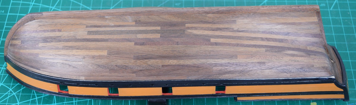 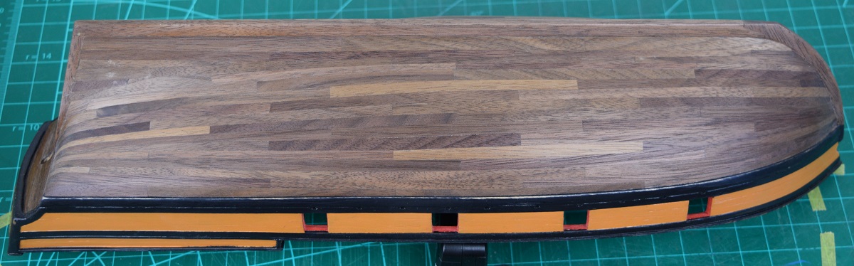 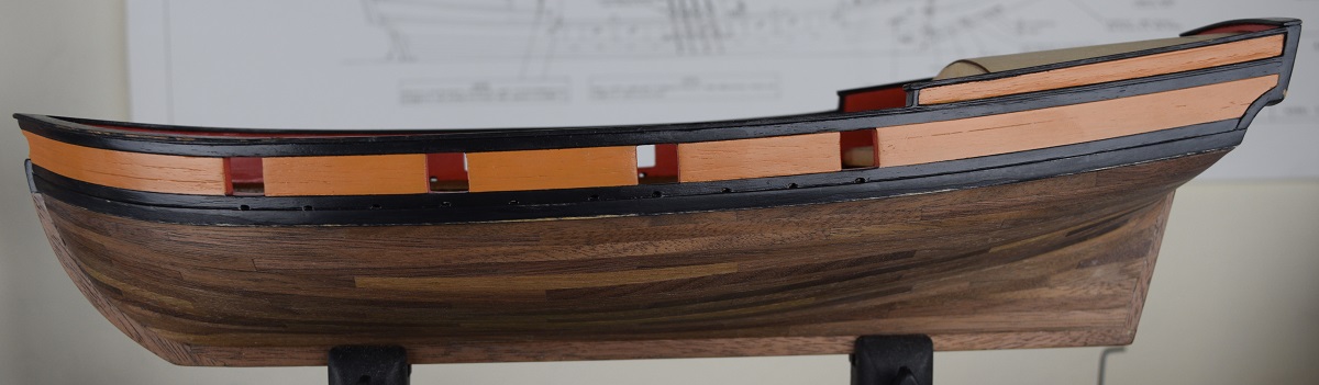 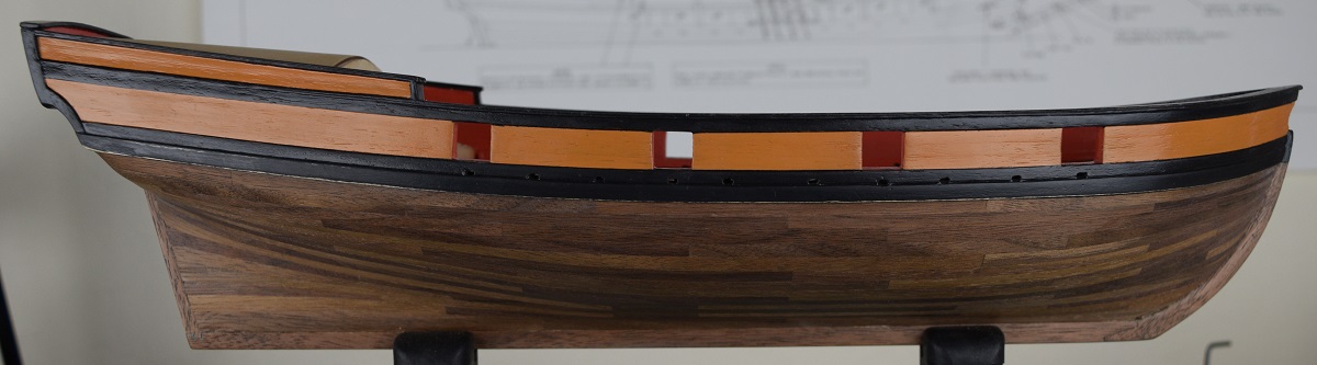 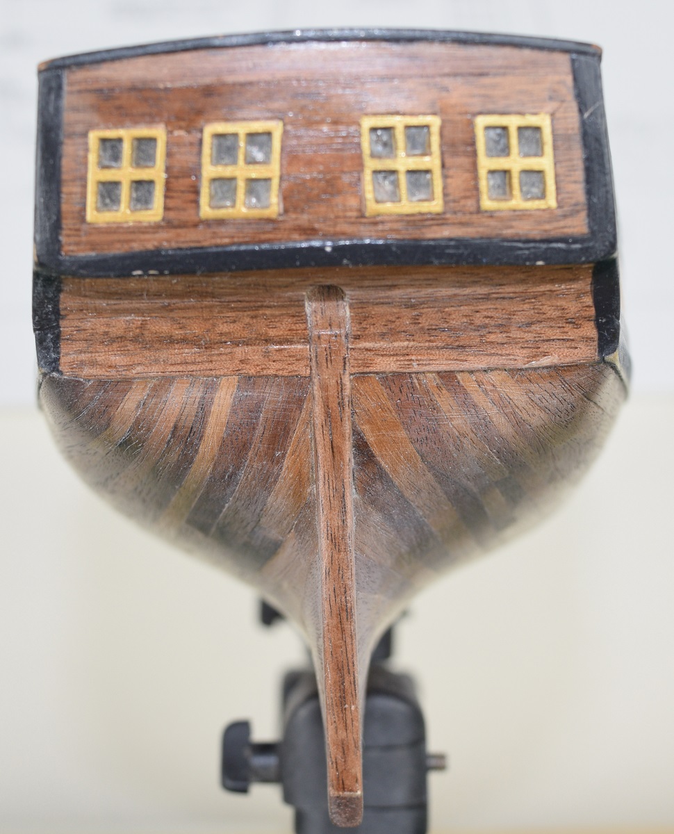 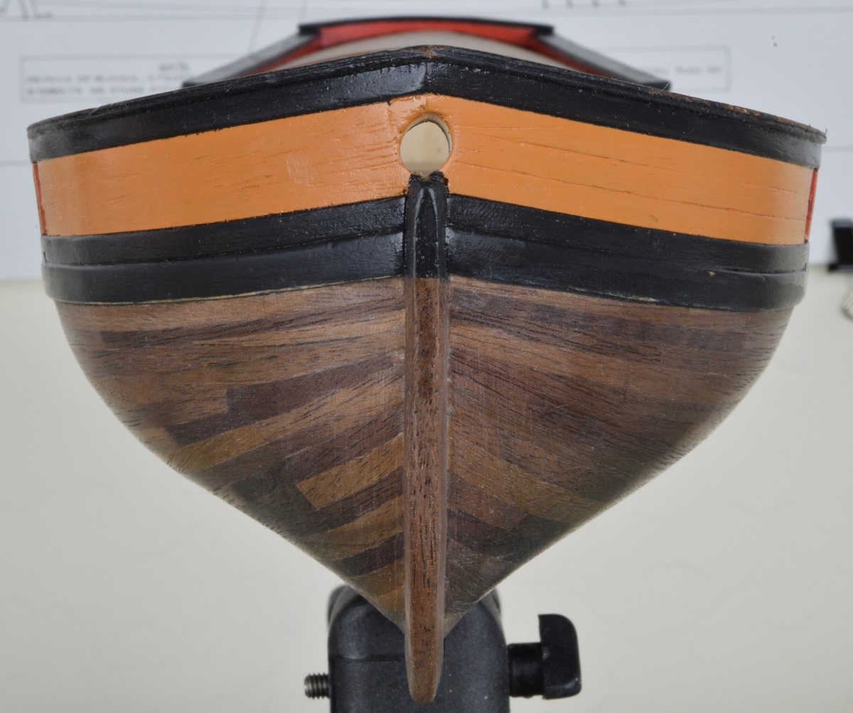 As you can see, I failed at the symmetry at the stern, which I'm not terribly happy about, but the rest looks pretty good to me, and I am not going to cover it with paint as I really like the way the different colors of walnut came out. I'm also happy that I mis-read an instruction and used 4" planks instead of 5", as even though they are fairly short in scale (16'), I think they make the hull look quite nice. I also used a 4-butt shift pattern for the planking, which came out quite well except for the aforementioned mistake when I laid the garboard strake at the wrong shift point. I've now got it all re-masked for touching up the black paint, and am about to start working on marking the locations for the sweep ports, and making a jig for drilling them. SA Note: This brings the log up to mid January, so approximately 3.5 months into the build.
|
|
#
?
Oct 30, 2020 03:42
|
|
|
I don't know anything about ships (real or model) so I don't have anything meaningful to contribute, but this is really interesting even if I occasionally get lost in all of the names for ship bits (reminds me of reading Aubrey�Maturin). I can only aspire to the patience it must take to actually complete a project like this.The Locator posted:I'm sure that could be adjusted in post by careful cropping, but I'm not a post-processing guru by any stretch, and the time and effort to learn how to do that wasn't something I was willing to do for this. On the off-chance that you happen to have access to it, if you load all of the photos into layers in a Photoshop document Edit > Auto-Align Layers does a surprisingly good job of repositioning images of the same thing to all line up without any effort.
|
|
#
?
Oct 30, 2020 13:50
|
|

|
Wallet posted:I don't know anything about ships (real or model) so I don't have anything meaningful to contribute, but this is really interesting even if I occasionally get lost in all of the names for ship bits (reminds me of reading Aubrey�Maturin). I can only aspire to the patience it must take to actually complete a project like this. Thanks. I do not have Photoshop, but if I ever decide to try to do a time-lapse for something that justifies this I'll keep that in mind, or maybe check and see if Gimp has the same feature since I can install that for free! Sorry about all the ship-bits terminology. I've tried to add in notes here and there explaining some of them, but I know there is a lot that I've missed. I learned all of the terms while building this model and making the log because you really need to learn them in order to actually know what parts you need and/or are working on and short of a long explanation there's not another way to identify things on these ships. Unlike port & starboard which I could just use left & right instead, the actual parts of these ships typically don't have a different word that everyone knows! It was extremely important in the day to have no confusion when talking about something on a ship (or when sailing, what the captain was ordering) so the words for things were fairly unique to the wooden ships in the age of sail. Many have carried forward into modern sailing vessels and even non-sailing vessels where they still apply.
|
|
#
?
Oct 30, 2020 17:12
|
|
|
I think I may have a new criteria for kit buying. Does it have odd shaped sweep ports (i.e. not square)? If yes, run away! SA Note: Sweep ports are the holes cut into the bulwarks where the crew can extend sweeps (long handled oars) to move the ship (slowly) when there is no wind. Also used for maneuvering probably around docks. The entire time I'm working on these I'm deathly afraid of slipping and making a mistake that will wreck hours or days of work. I'm halfway home, and managed to get them ok looking, if not great, but also managed to mess up all three colors of paint so more touch-up will be coming down the road. Shocker! Will finish up the starboard side ports tomorrow. Here are the port side sweep ports, obviously not painted yet. 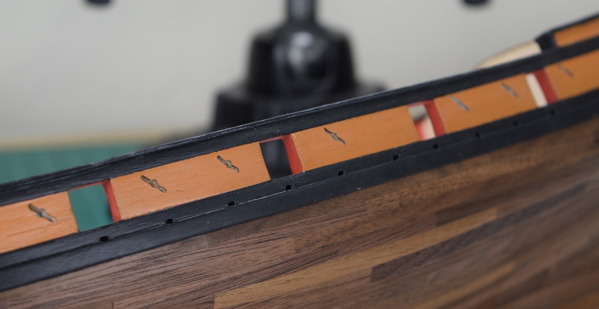 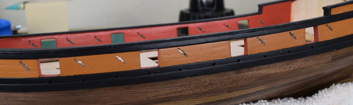 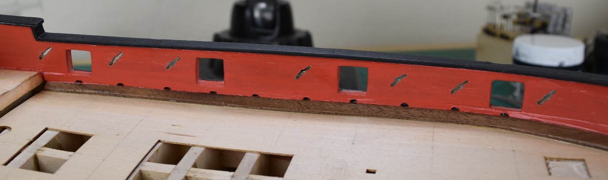 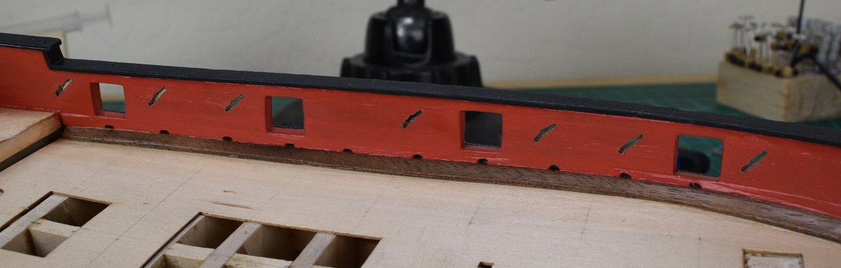 I did these by first transferring the center point for each port by making a direct tracing of the plans, and just taping that tracing to the bulkhead and using a sharp point punch to mark. I did this while the bulkheads were masked, inside and out with masking tape for doing the black paint touch-up. I then made a small brass jig with the center and end holes in it, and then positioning the jig over the center punch marks and drilling the three holes with a 3/64" drill (actually 1.2mm, but that's only 0.01mm off). I then came back and drilled the center hole with a 3/32" drill. I connected the holes with a small X-acto saw while it was still masked. After finishing the touch-up work on the black paint, I removed all the masking, and enlarged the connecting line between the holes with a #10 X-acto blade, working very slowly and shaving a tiny bit off at a time, doing first the outside, then the inside, and then working to open up the middle to connect them evenly. The port farthest aft is pretty lopsided, but the rest came out decent. ------------- I'm done with the sweep ports. Not because I'm particularly happy with how they came out, but because I kept trying to make them better and was at the point where I think I was starting to make things worse, rather than better. So I reached the 'good enough this time' point and called it done. A few of them came out pretty good, but there are a number that under the stare of the optivisor or macro lens, make me.. unhappy. Oh well. Close up of a pair of decent ones, before touch-up painting. 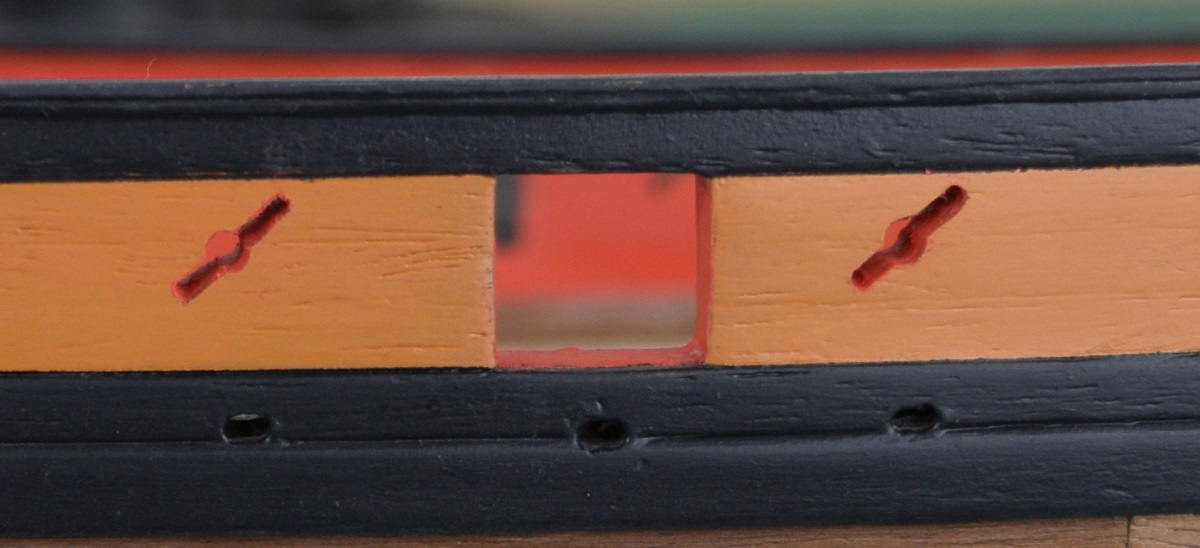 And some generic shots of both sides. 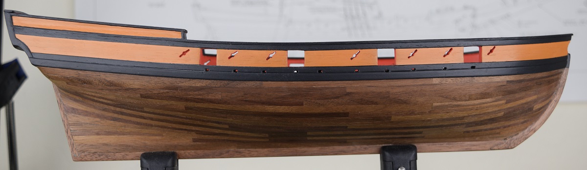 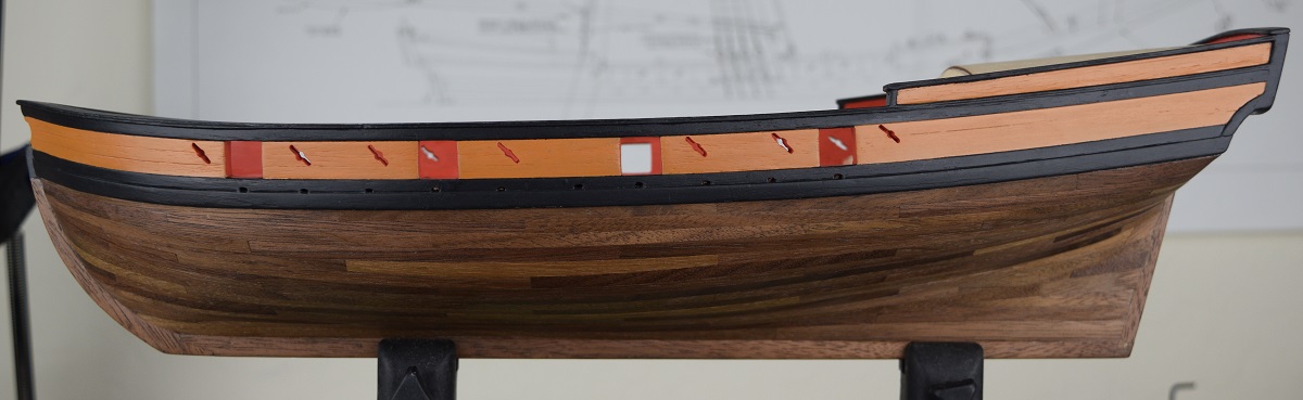 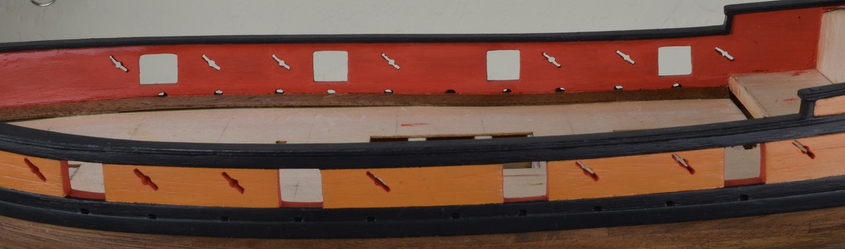 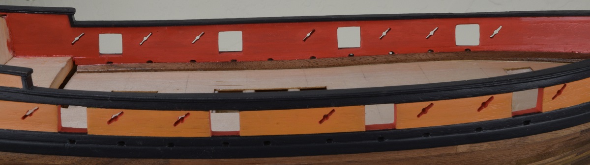 Now I get to start on what I hope is fun and interesting, building the deck furniture so that I can plank the deck! ------------ Today.. I managed a true facepalm while making my very first coaming. SA Note: Coaming is the 'frame', for lack of a better word where the various things on the deck fit into the deck planking. The coaming hopefully prevents seawater from flowing from the deck down to the insides of the ship. So the coaming frame calls for walnut that is 3/32" thick x 1/4" wide, but the actual walnut in the kit is actually only 1/16" thick, 1/32" too thin. So I decided I'd improvise, and I cut some matching pieces of 1/4" walnut from the .030" planking and glued it to the 1/16" walnut to make a laminated piece that was almost exactly 3/32" thick. Worked great, and I moved on to adding the inner 3/64" pieces that the cover planks would rest on later. I put it all together and on my very first try it looked really good. The next step is to bevel the entire edge of all 4 faces of the coaming to be 1/32" narrower at the top than the bottom. I focused intently on doing this right, as of course if this goes wrong the entire thing is garbage, so when I finished it, I was really quite happy, as it looked like it came out much closer to perfect than I could possibly have expected for my first try at one of these... 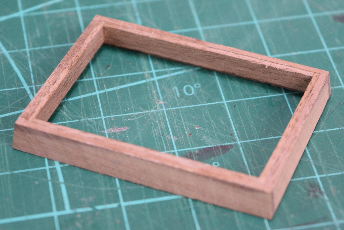 Right up until I went to look at how the planking would fit, and realized that I had beveled the edges upside down... 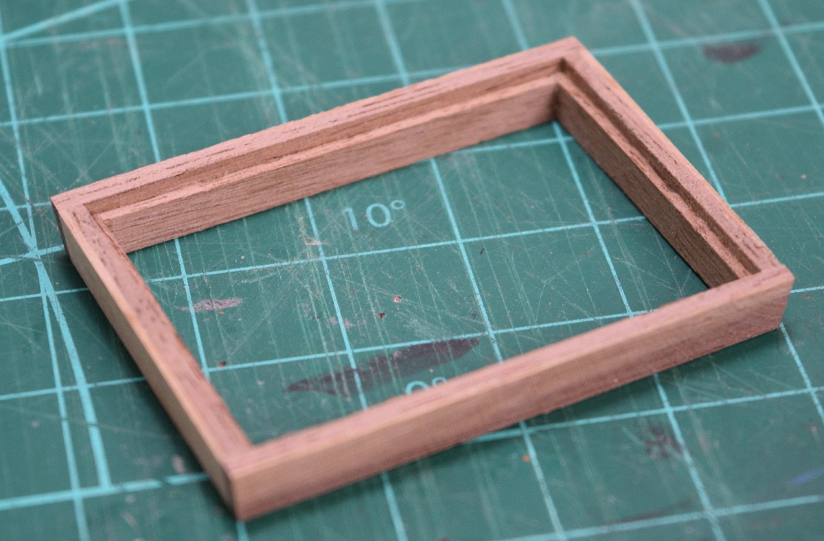  Oh well, it was a practice run! That's my story, and I'm sticking to it. This is why wooden boats take so long to make! ----------------- I've gotten the main hatch, and the scuttle port completed - I am using cherry for the planking and the kit walnut for the coaming, I think it makes a nice contrast. The hardware was chemically blackened. 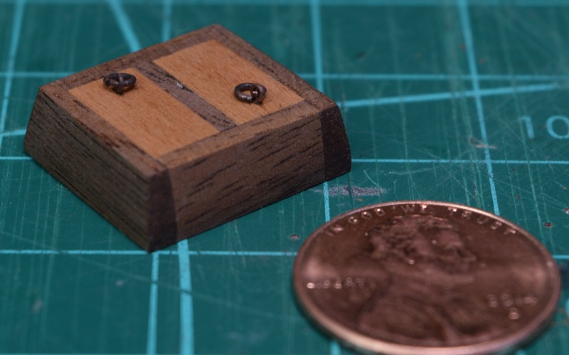 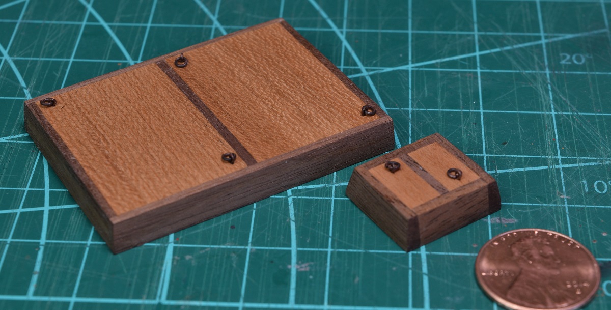 SA Note: Up next I am going to put together a long post on the actual construction of the deck furniture, which was not part of the original build log. Not sure if I'll get to it late tonight, or sometime this weekend.
|
|
#
?
Oct 30, 2020 21:27
|
|
|
So lets see if I can make a reasonably coherent post on making deck furniture. Deck furniture? Glad you asked. For some reason steeped in the depths of time, all of the 'stuff' that protrudes above the deck of the ship is known collectively as 'furniture'. Things like hatches, ports, companionways all together are called furniture. Because the deck planking has to butt up cleanly against all of this furniture, and no matter how 'good' I am they will vary from the actual plans a bit, these need to be completed before planking the deck so that the deck planking can fit properly. For this ship, there are 4 primary pieces of deck furniture that fit into the decking instead of just sitting on top of it. Two hatches - the main hatch, and the scuttle port which were pictured above. The main hatch is where big stuff can be moved to/from the lower deck. The scuttle port is the access to the anchor rope storage, and eventually the anchor lines will go through some notches cut into the covers. There is another small hatch that sits where the ships galley would be, and instead of a solid cover it has a grating to allow light/air in. Generally the gratings were also removable. Finally the largest and most complicated piece is the companionway. This is where the ladder for people moving from below to/from the deck is located and it has a double-door and a fold-back top. So, on to the actual building of these things. Do they come with nice laser cut pieces to assemble? Of course not! You simply take measurements off the plans, which do have some construction notes on them, and hack up various bits of wood to make appropriate sized pieces and then shape them as needed. Effectively, just like many things on these models, this is all scratch built. Here is how the scuttle port was constructed, step by step (sort of). Chop up some wood for the coaming. Glue the wood that will support the planks to the coaming to form a ledge. Use a 90 degree angle to get the corners right and glue them together. Use a caliper to mark how far in to sand to get the bevel correct. Sand the bevel in, but the bevel doesn't actually start at the bottom, it starts one plank-thickness above the bottom as the deck planking needs a flat surface to butt up against or it won't fit right. I used a disk sander to do the primary sanding of the bevel and then final finish was done on sandpaper attached to a flat surface so I could move the wood back and forth on it for a very flat result. 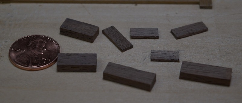 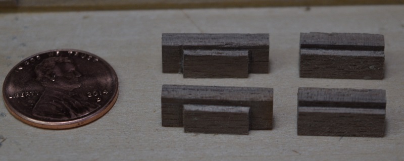 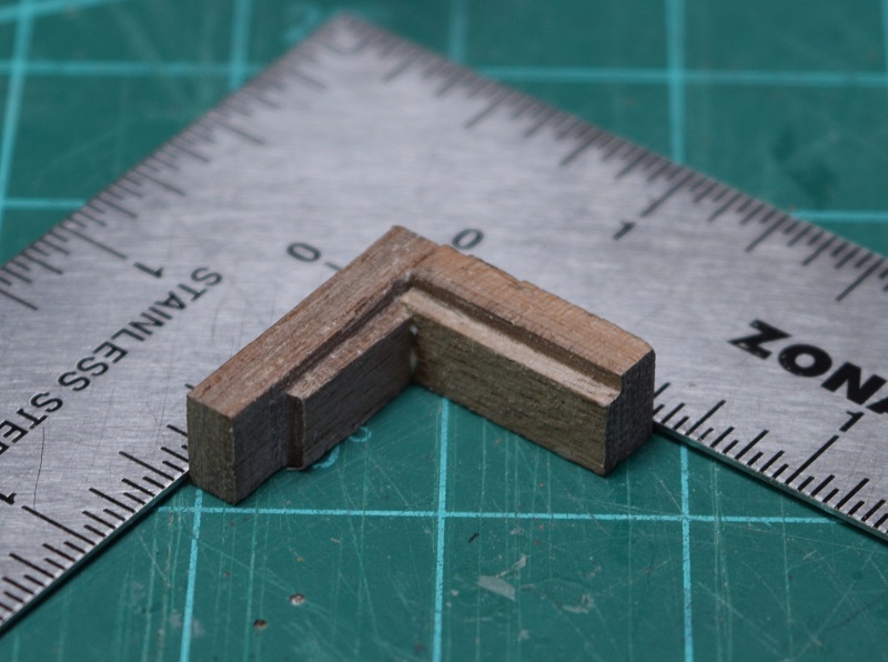 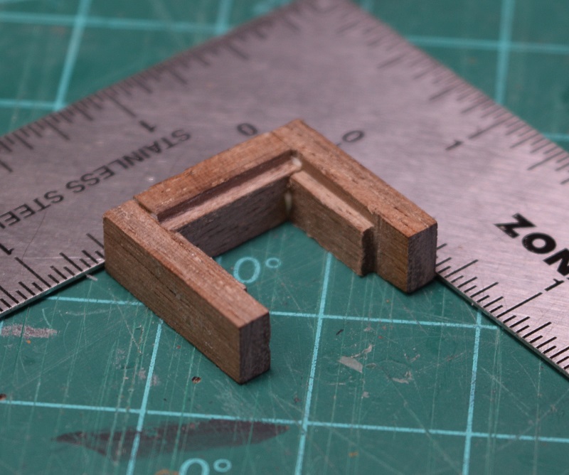 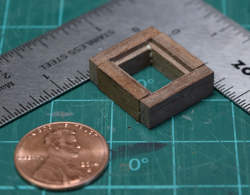 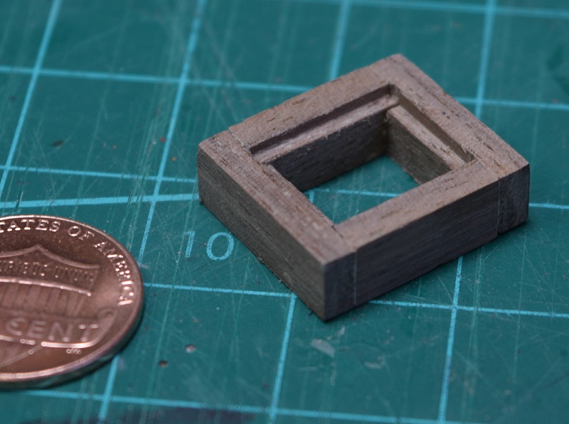 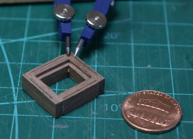 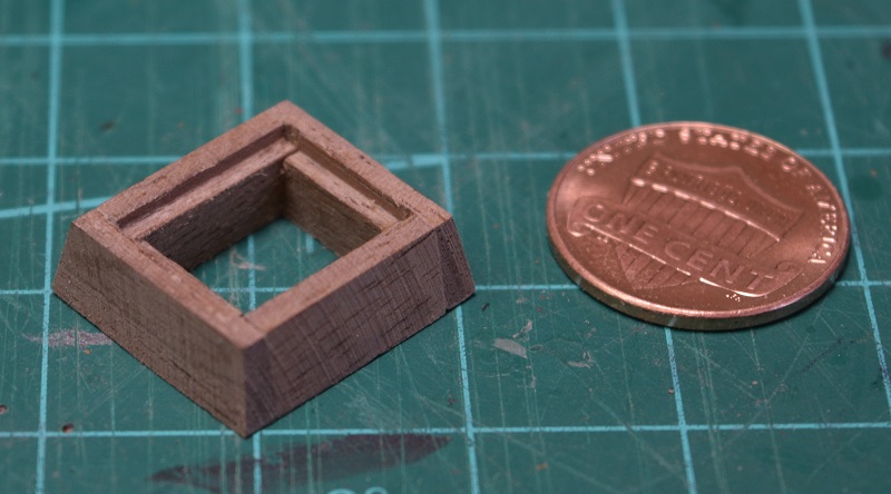 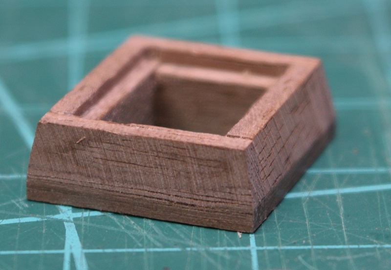 Now that we have the coaming complete, it's time to build the covers. In this case it's got a center bar, and two small removable plank covers. I used the kit walnut for the coaming and the center support, and used some cherry wood for the planking. A small brass eyelet? and ring are fit together, chemically blackened, and glued into small holes drilled in the planks. The crew would grab those to yank the covers off. 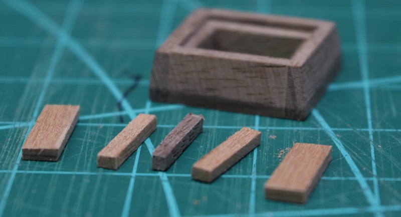 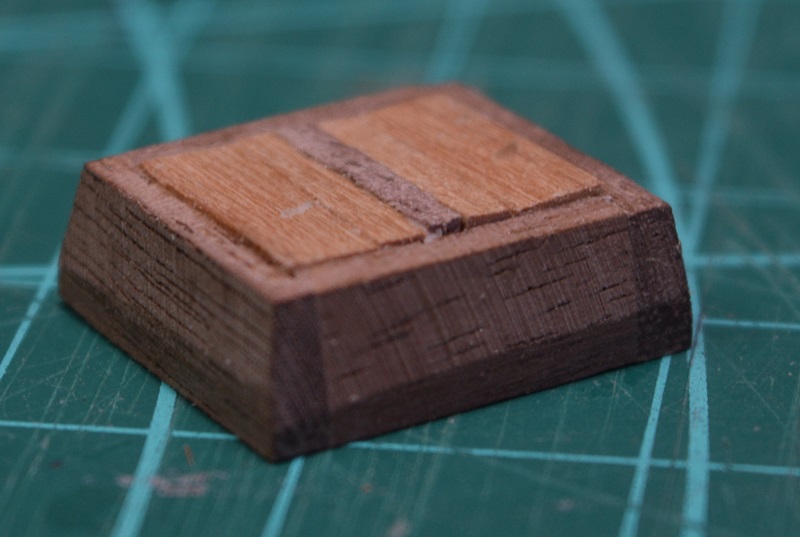 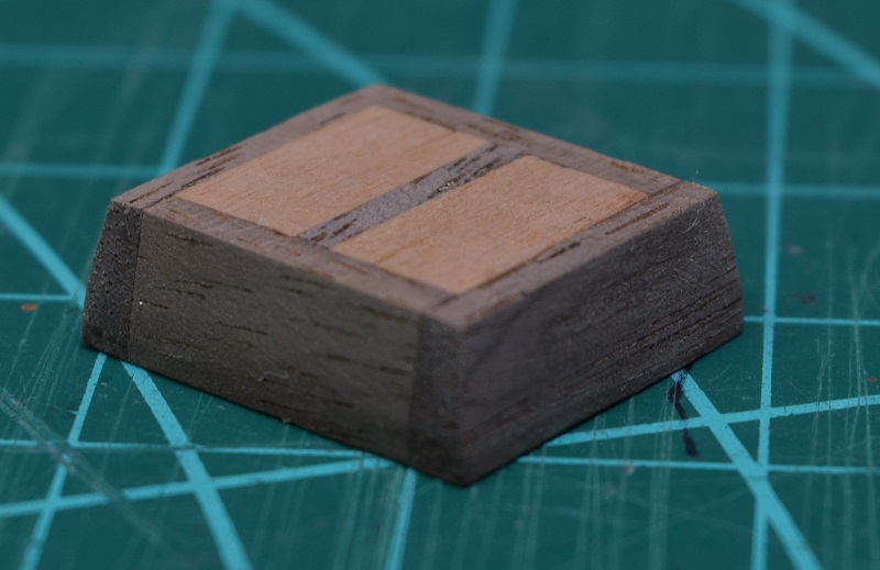 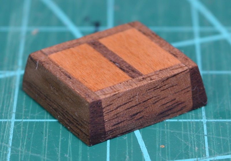 So that's how the construction of the main hatch pictured in the last update was done also. Only difference between the two is overall size. The companionway though, is a different beast. Like the hatches, I start out with just various sizes of strip wood, and make a coaming which will be the base of the companionway.  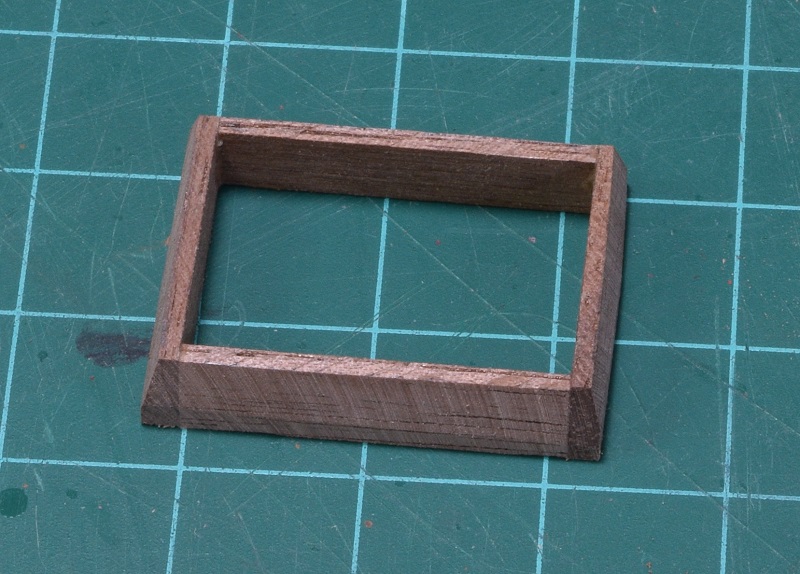 With that out of the way, I start working on building the 'walls' of the companionway, starting with the back wall, since it is the simplest one. The planking will be cherry like the hatches, but it won't be planked until the frame is all done. 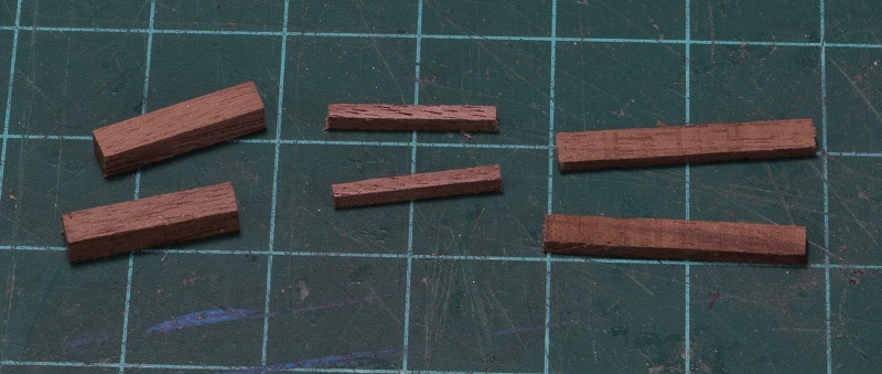 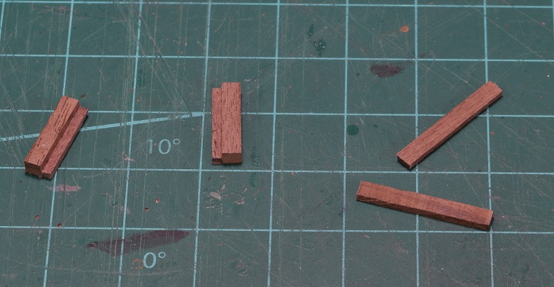 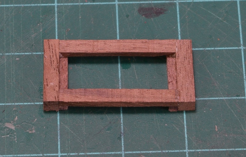 Next up is the front wall. It's much more complicated because of the double door design, but it's still got square corners so I tackle it next. Like everything, it starts out with bits of wood that form the main frame with thin wood forming the surface that the planks will attach to forming a recess inside the frame. 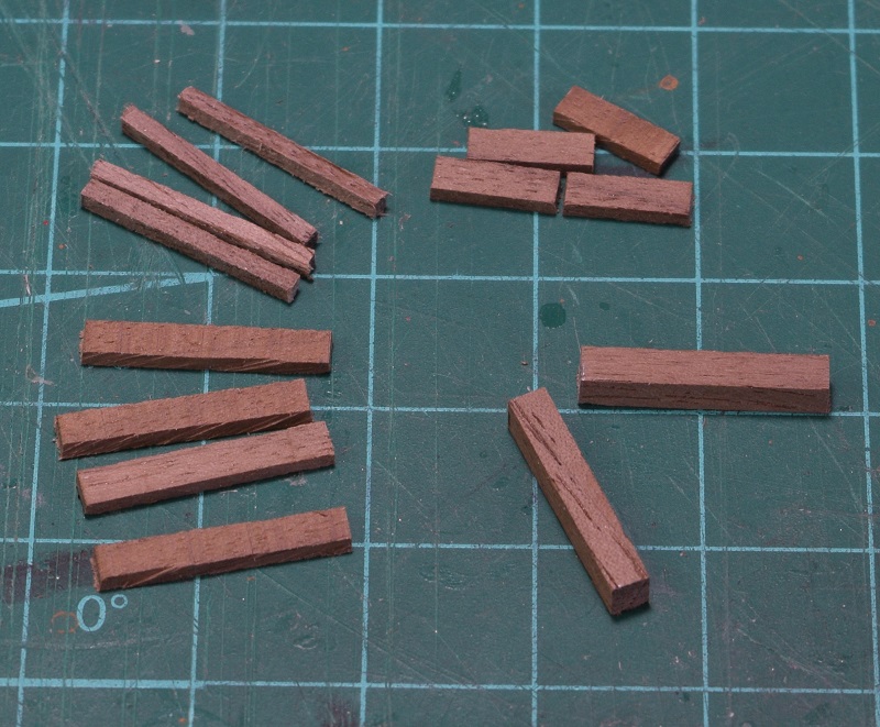 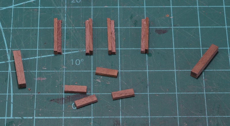 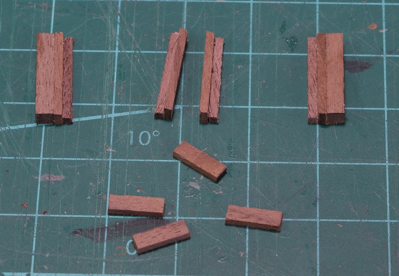 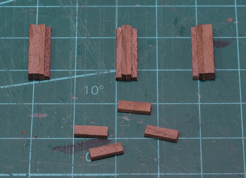 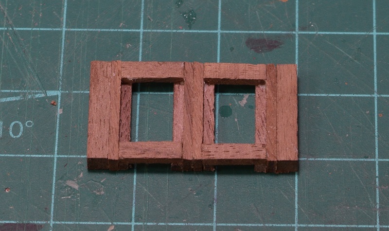 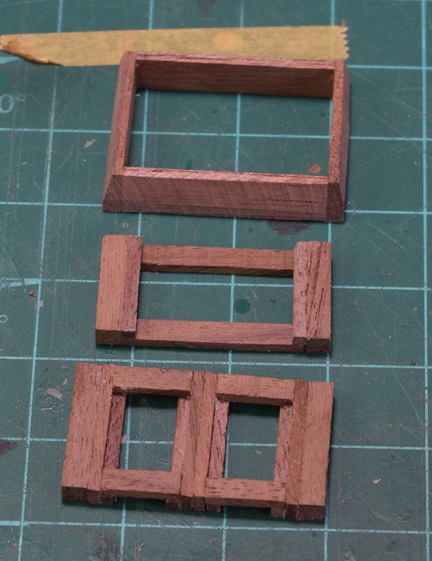 As seen in the last photo, I now have the coaming, the back and the front walls. As you can see, the front wall is 'taller' than the back wall. Because of that, of course the side walls are not rectangular, the top is at an angle. I decided that the easiest way to make this work is to put what I currently have all together leaving only the angled top to custom fit to the assembly. This meant adding the interior bracing that the planks would land on to the existing parts as well as the 'base' of the wall attaching them together. 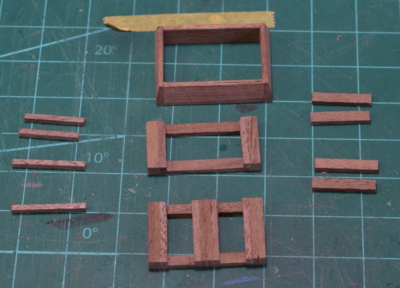 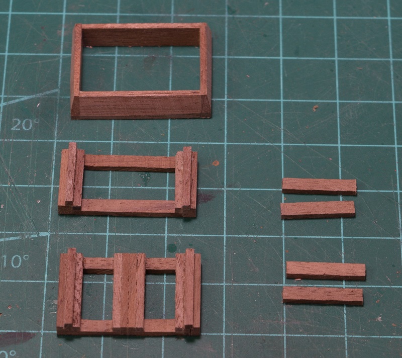 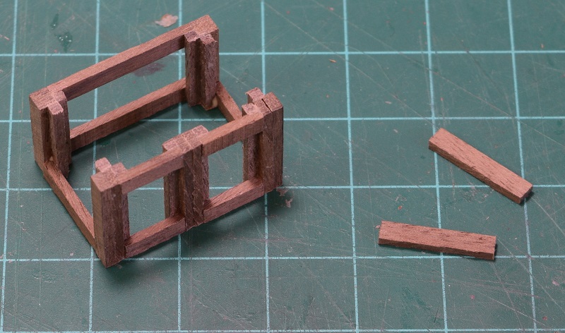 Now I could make the tops of the side walls and have them properly fit. I then started adding extra interior pieces of wood for the planking to glue to top and bottom and began adding the planking for the walls. 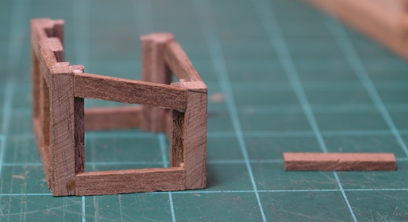 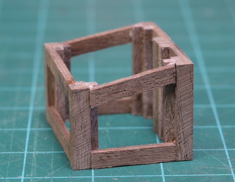 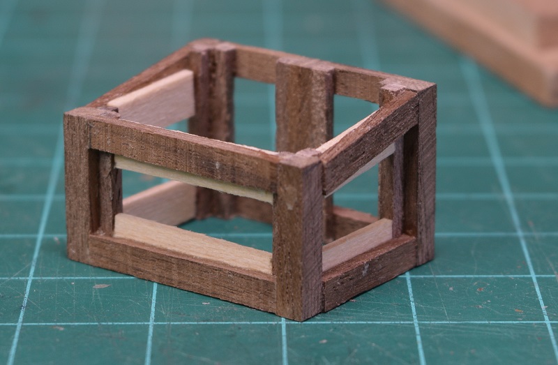 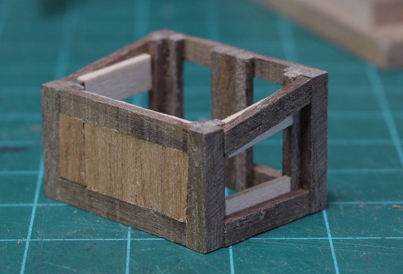 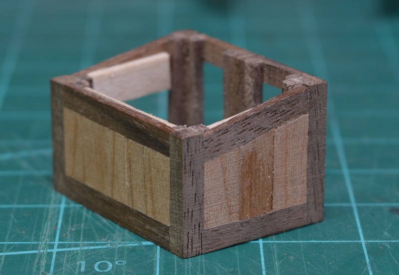 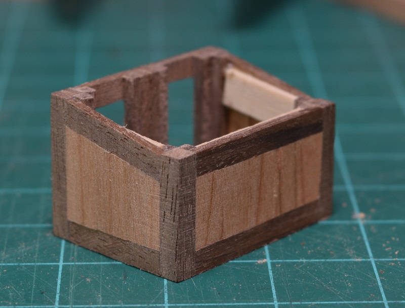 Once all the wall planking was done, time to attach the walls to the base (the coaming). 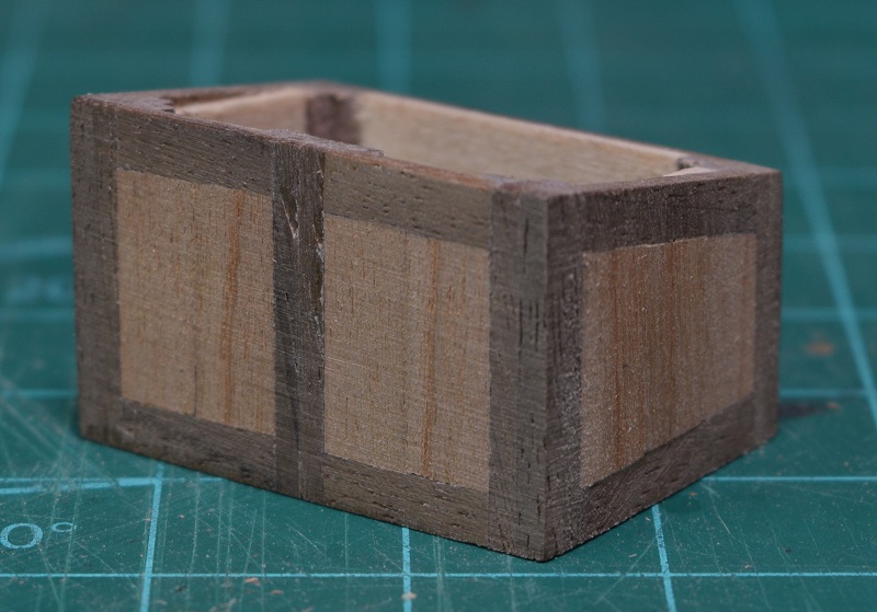 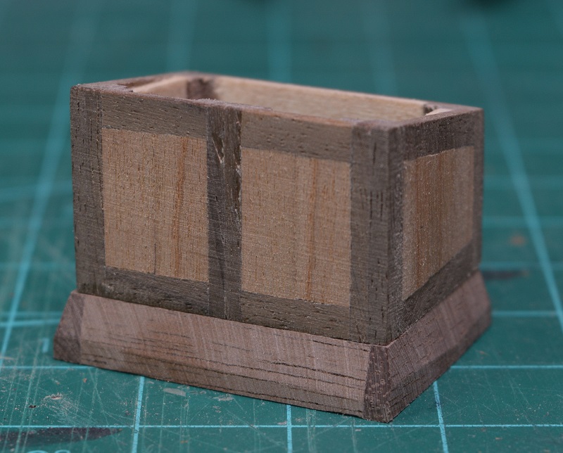 As can be seen in the final picture above, the tops of the vertical wall supports are now magically matching the angle of the side walls. This was done by the simple method of sanding them down on the flat piece of sandpaper until the top was completely flat. Of course the companionway can't be left open to the sky, it needs a roof, and the design of this roof is quite simple. 5 planks glued edge to edge. The real companionway would have the first two planks fold back on hinges to give more headroom to people using the companionway ladder (the companionway is only about 4' tall in scale). This is typical of sailboat access to lower decks. Everything is kept fairly low to the deck. After gluing the planks together (kit walnut was used) I cut little bits of brass out to make the hinges. The fake little hinge pivot was made using bits of brass rod. It was all assembled and then I used tiny droplets of CA glue to simulate the bolt heads and then it was all painted black. The door hardware was made by bending black wire to shape and drilling small holes to stick the wire into and gluing it. 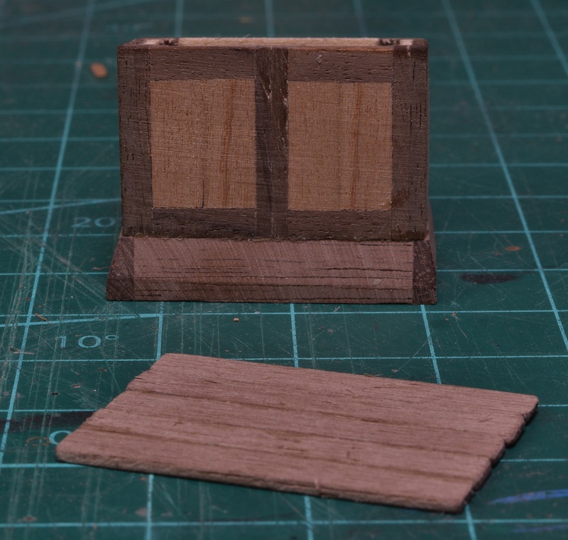 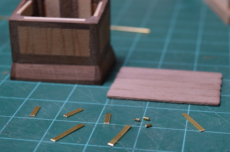 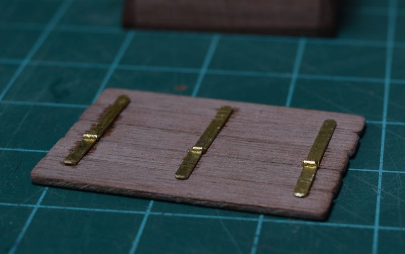 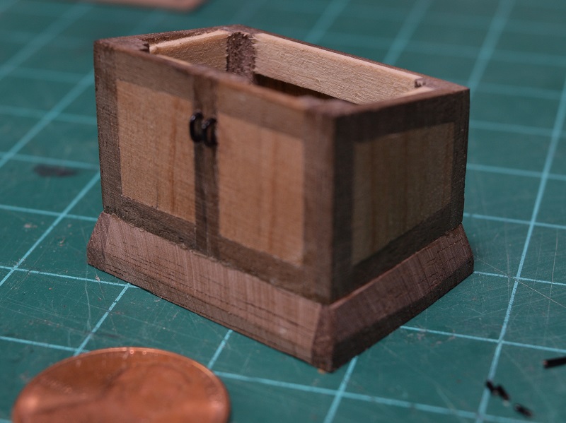 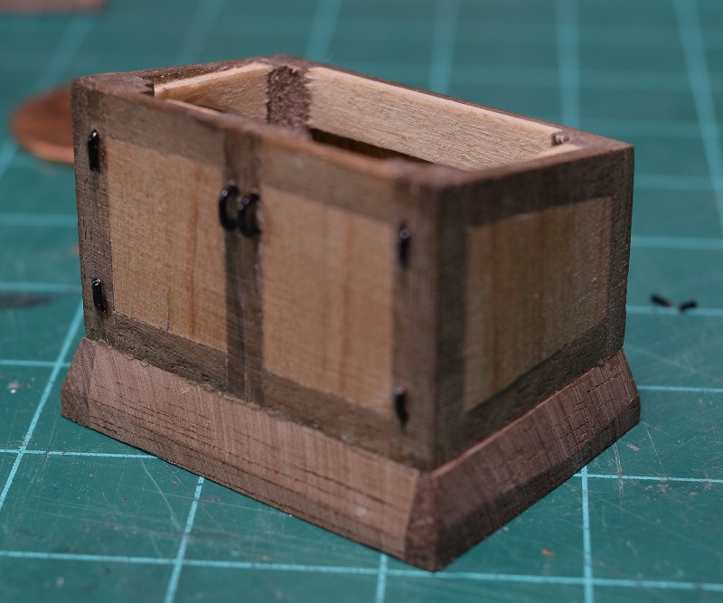 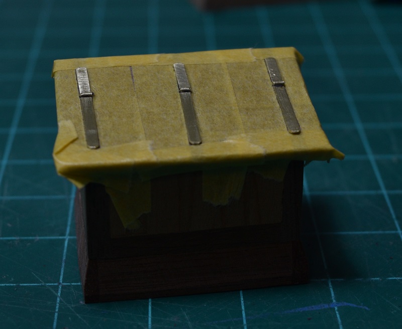 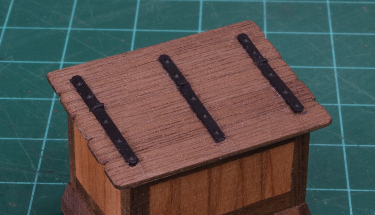 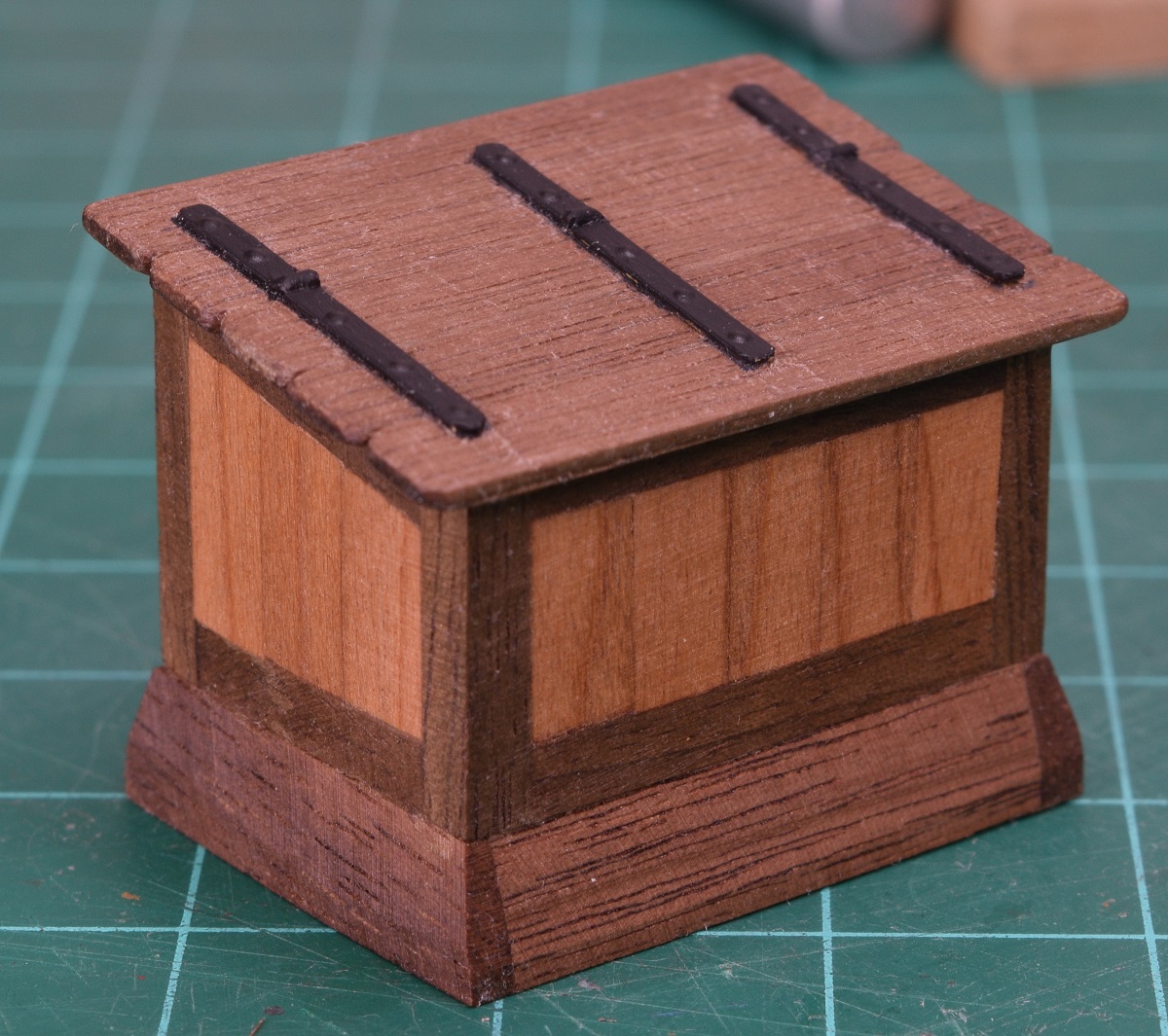 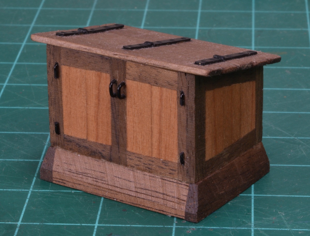 I went back when I finished making this companionway and counted bits, it has 73 parts, not a single one of which is pre-made. So I suppose the hatches and the companionway are really my first little scratch built models! The final hatch is the grated kitchen hatch, which is made just like the others, a coaming is made, and then a grating is made to size to fit in it. My first one was made to the size the plans showed, but that left the grating looking really strange. 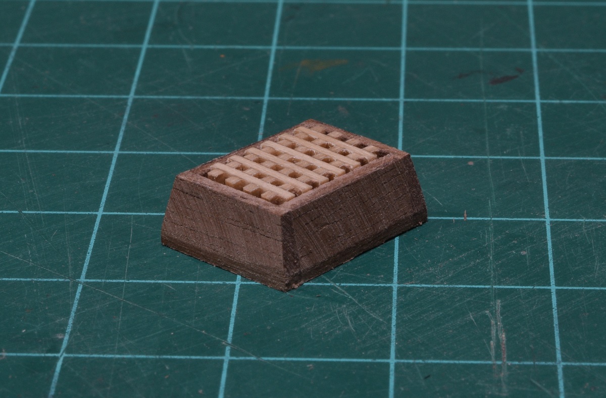 The grating on this type of hatch is removable, so it would never have the grating itself not have an outer frame like this. So I tossed that one in the bin, and built a new one, but backwards. Instead of building the coaming first, I built the grating the way it should look first, and then fit the coaming to the grating before beveling it. I probably go over this a bit in the actual original build log so you might see this again! 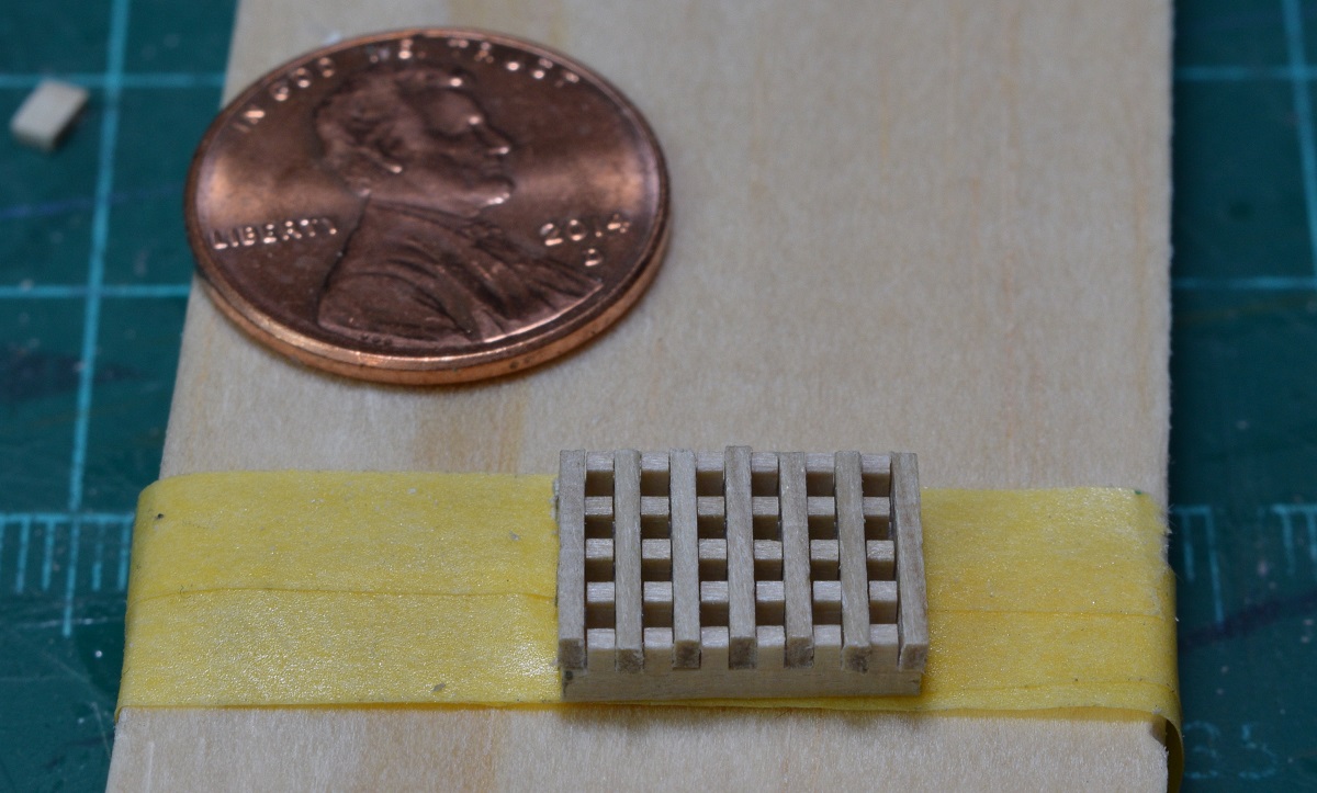 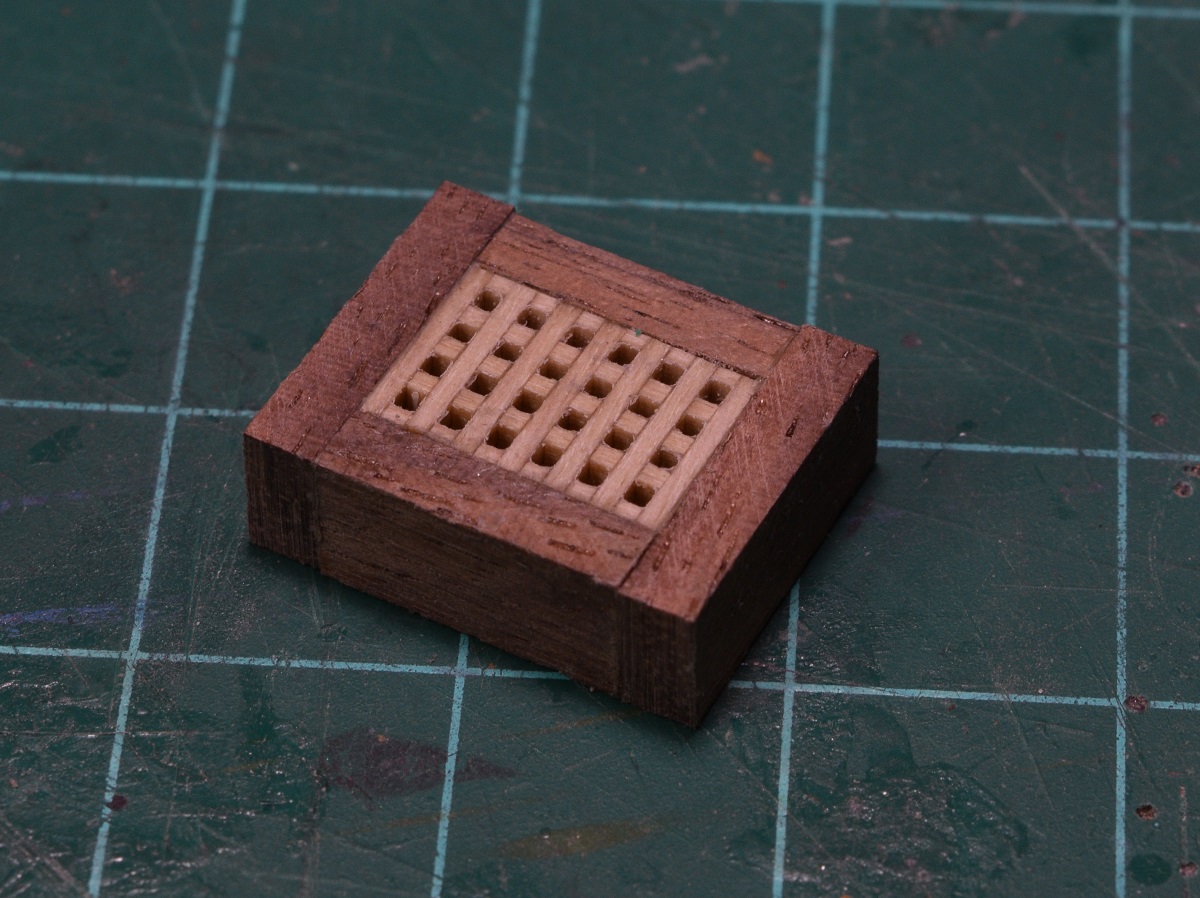 And all the furniture (including the ugly kitchen hatch that I eventually toss and remake) sitting in their approximate locations on the deck. 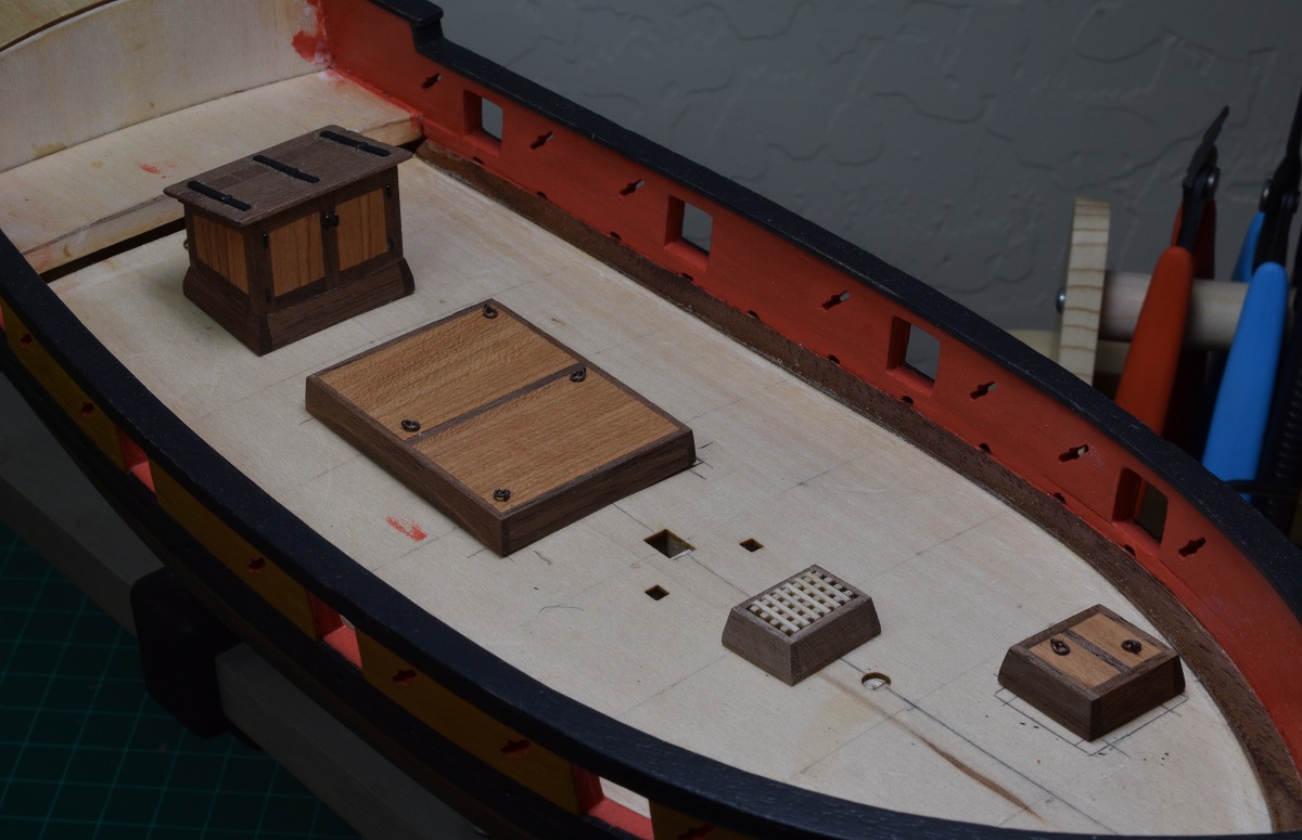 Ready to start the deck planking! Edit: Fixed links The Locator fucked around with this message at 17:58 on Nov 1, 2020 |
|
#
?
Nov 1, 2020 17:47
|
|
|
SA Note - next update is a little bit out of sequence for you guys because you already know about the kitchen hatch re-make, when during the build it happened after deck planking had started. I mention it seeming 'off' to my eye in the original build log in a general conversation, not part of the log. The deck planking is the first 'major' departure from the kit/plans for the build. Previously I've used a few small parts like the cherry wood for the deck furniture, and the boxwood for the wales, but it's pretty much been made from the kit up to this point with those minor variations. For the deck though, through some research into what a deck would properly look like for this period, I came up with my own planking pattern, and for the wood, instead of using the basswood from the kit, which is a fairly soft wood, I am completely replacing the wood with a lovely white wood named holly. Let's start planking the deck! So I figured out what is wrong with the galley hatch. It isn't the grating, it's the coaming itself - it is ever so slightly out of square, and I'm not sure why. Measured from 2 corners it's square, but from the other two it's not. I messed up a tiny bit somewhere, but it's enough that my eyeball catches it as being 'off'. As a result, the planking won't match up correctly unless I fix it, so the next order of business will be making a new galley hatch tomorrow night. I don't think I can make it with the grating having the outside edges like Frank suggests, as the grating material isn't the right dimension for it (works great across the short side, but doesn't work across the long side). I would have to go off-size on the plans to make that work, so I'm not sure I'm going to try. I'll take a fresh look at it tomorrow before I remake it to decide. I can't really explain why, but I really do enjoy doing the deck planking. It's going well so far, and I'm not going per-plan at all, rather I'm sort of emulating stuff I've seen in various builds here. We'll see how it works out long term, but I like the first little bit. 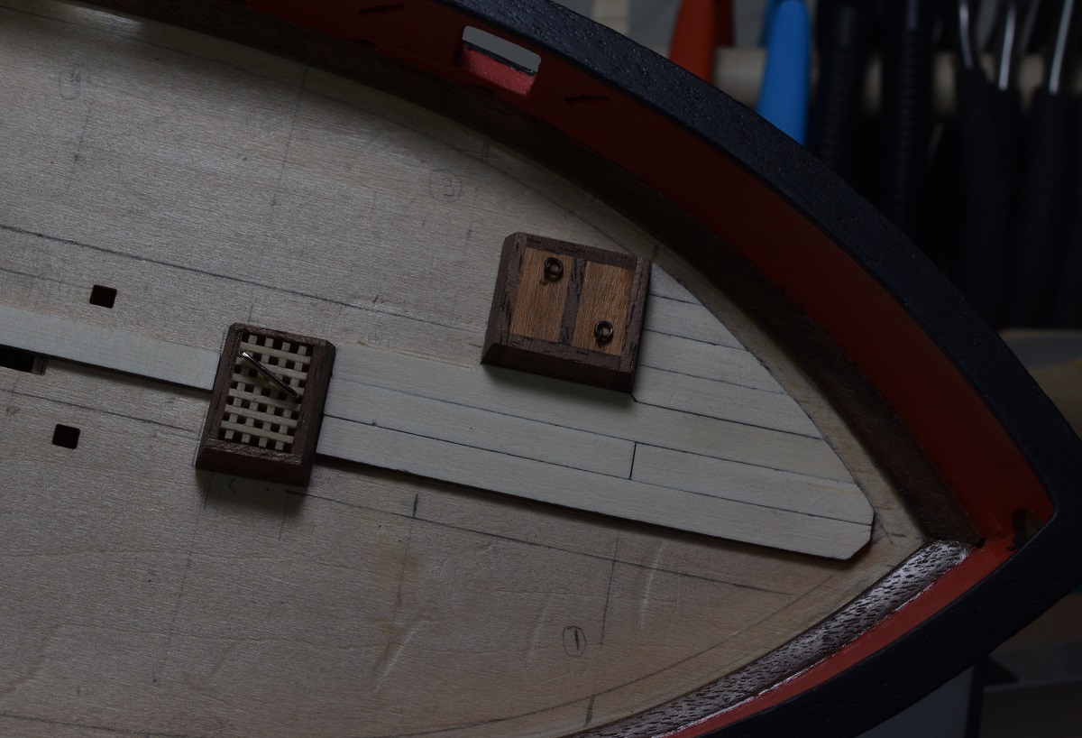 The hatches are not glued, they are just being used to the planking fitment, which is why I need to remake the galley hatch now, because I need it to be right before going any further with the deck planking. ------------------- SA Note: Next up was an update about rebuilding the kitchen hatch with the proper grating. I'll skip over the duplicate part of that and pick up with the fitting to the deck. After completing the new hatch assembly, I checked the measurement on deck. It was slightly larger than the original galley hatch, so I used a chisel and carefully trimmed back the already glued deck planking, filed the new edge flat with a riffler file, and then trimmed the final bit needed off of the single plank on the other side until it was a snug fit. I then slapped on a coat of poly, and ta-da! Here is the new galley hatch sitting in it's future home. 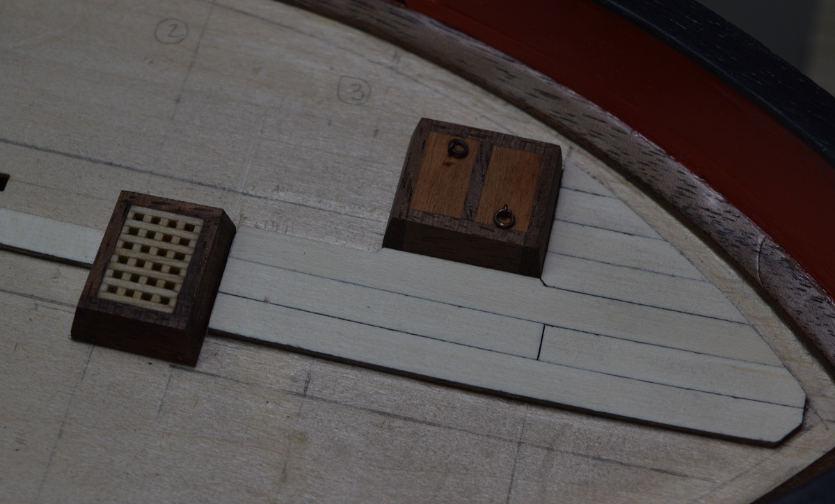 Puttering along with the deck planking now, the custom shaped planks alongside the hatches are pretty slow going, especially since I've had to remake 2 of the 3 along the way, but I think the end results will be worth it, I'm really liking it so far, and this holly is just wonderful to work with, it just blows basswood away, even ignoring the 'looks' part. 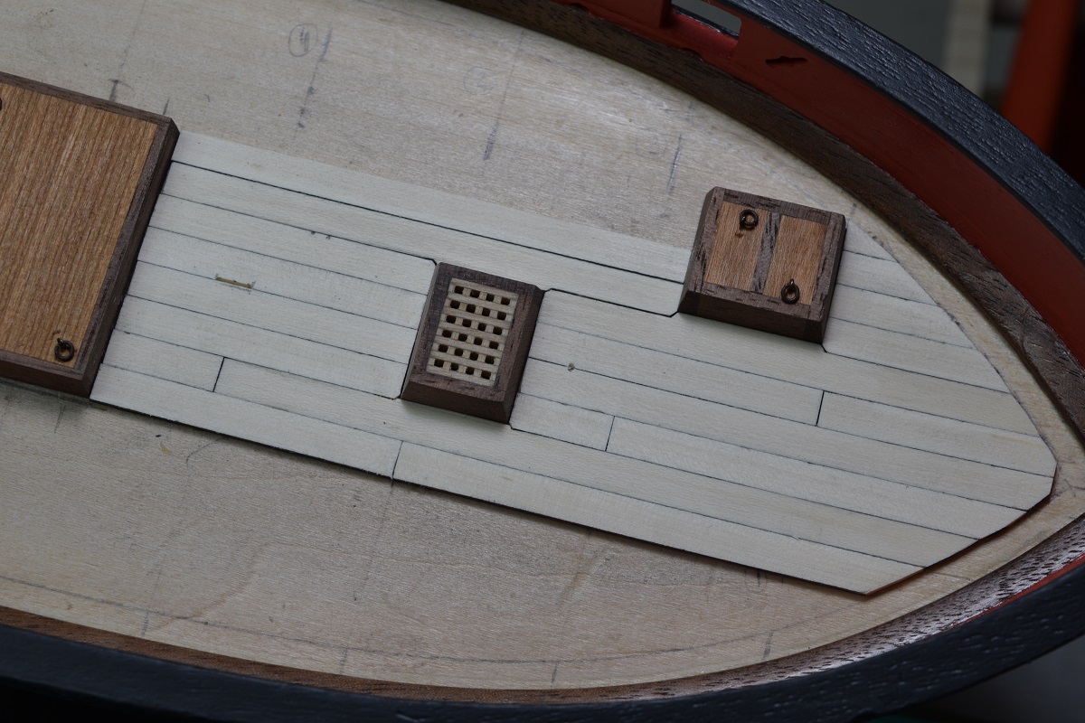 I think I'm going to place the margin planks very soon, instead of waiting until after the deck planks are in, as I've decided to go with hook & scarf planking into the margin, instead of nibbing, as that wasn't prevalent in ship building until 40 or more years after the date of this ship (see discussion on nibbing in the planking sub-forum). Since hook & scarf deck planks don't require the margin plank to be cut into, I think it will be easier to get a neat mating to it with the deck planks if it's in place first. ------------------------ Still pleased with the results, and haven't had to remake too many things (yet), but from here on out almost every plank will be hand cut from wider stock, so the potential for terrible results will increase greatly! I hope to cut the margin strakes, and maybe even finish the main deck planking tomorrow, but we'll have to see how slowly it goes as I cut all the custom fit edge planks. 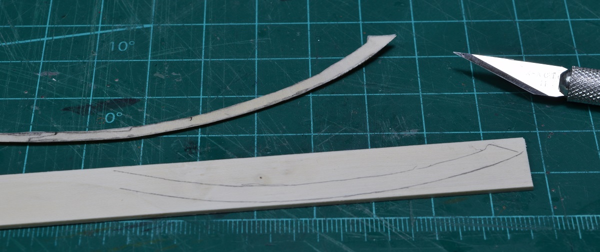 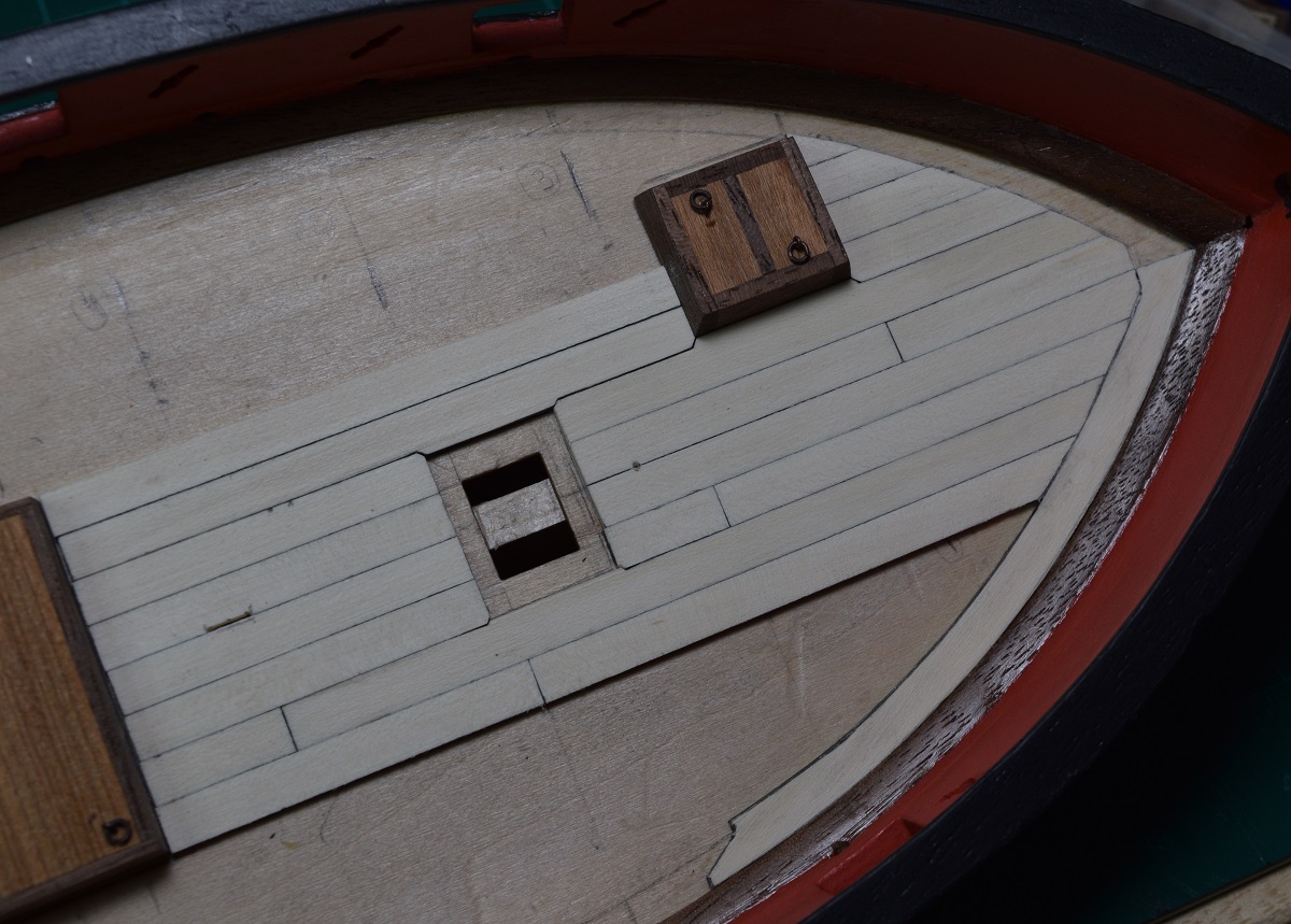 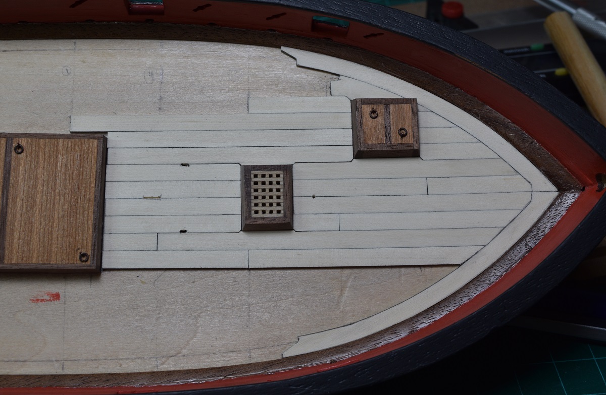 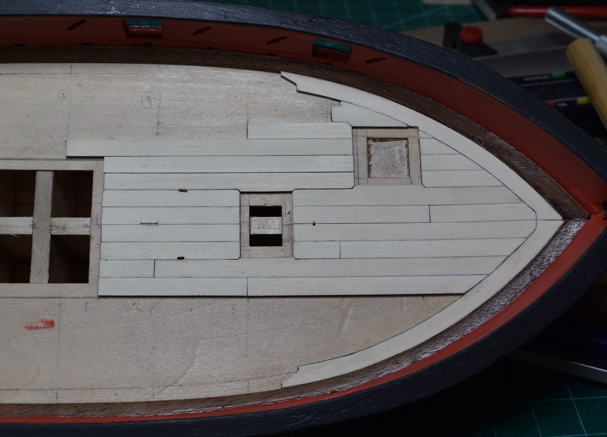 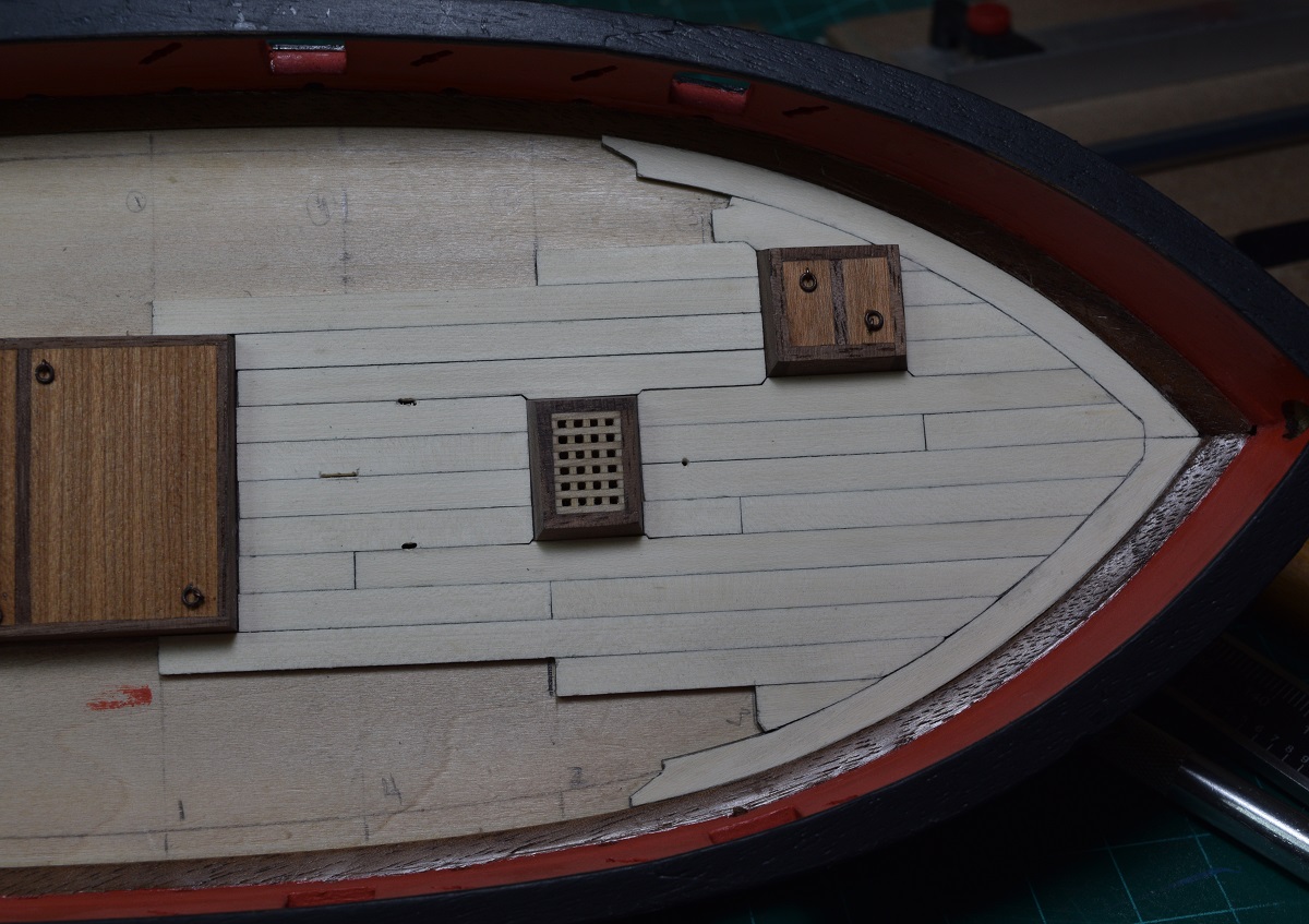 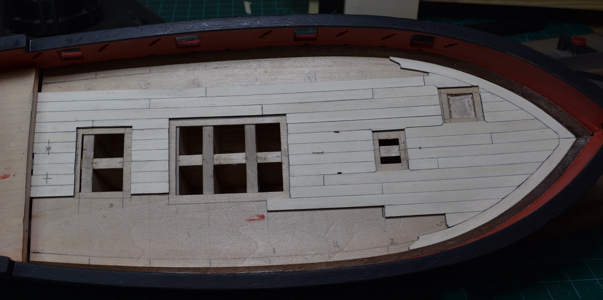 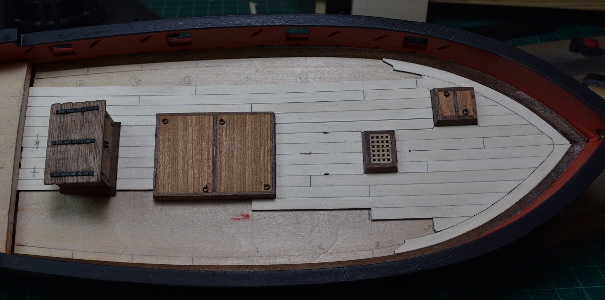 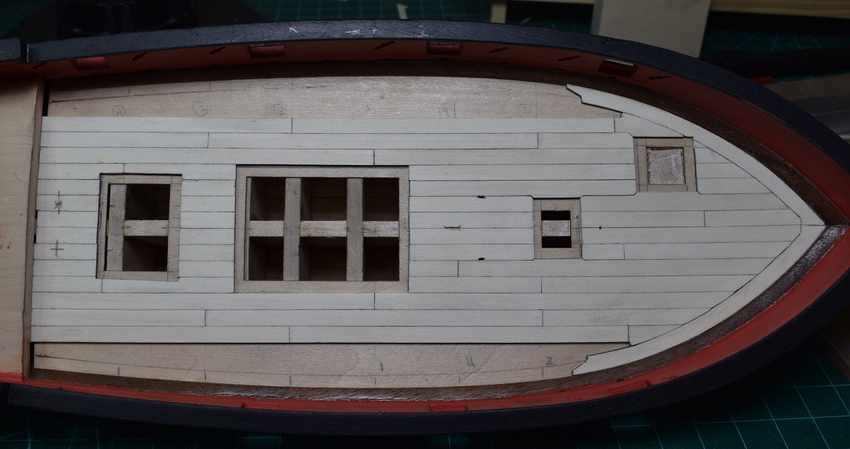 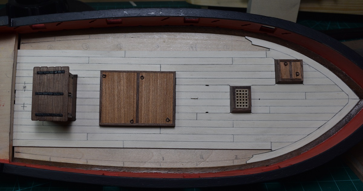 ---------------------- The main deck planking is all placed. I learned a number of things doing this, and in retrospect I would have done a few things differently (where the butt-ends landed, I should have started the hook & scarf at least one, and probably 2 planks earlier), but overall I'm fairly happy with the final results. 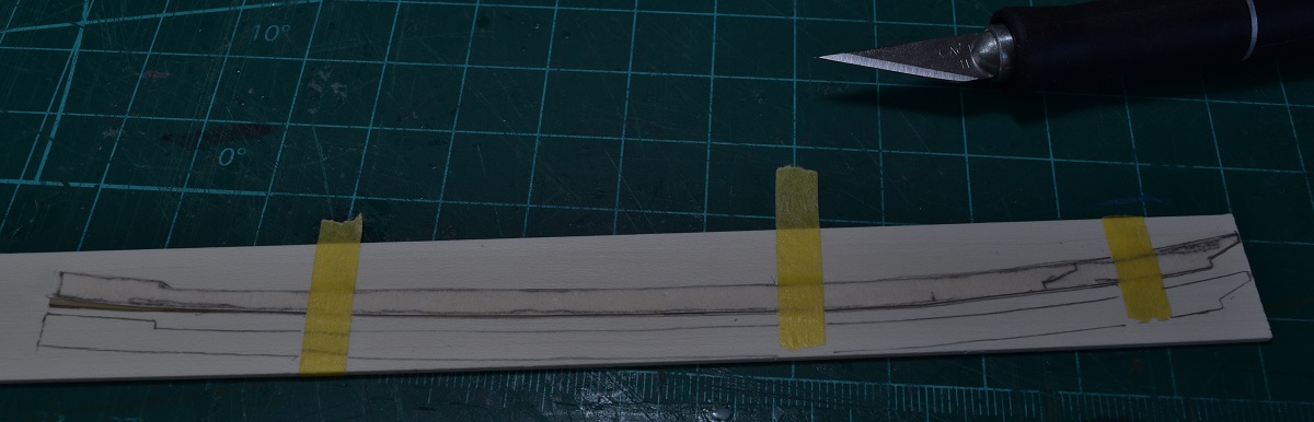 Now I need to plank the quarter-deck, and then do a full scraping and get a couple coats of poly down (oh, and open up the holes for mast, stove pipe, etc.) before drilling a bunch of little holes! I also need to make some small adjustments to the main hatch, and re-poly all the deck furniture which is all still just sitting in place, not glued. 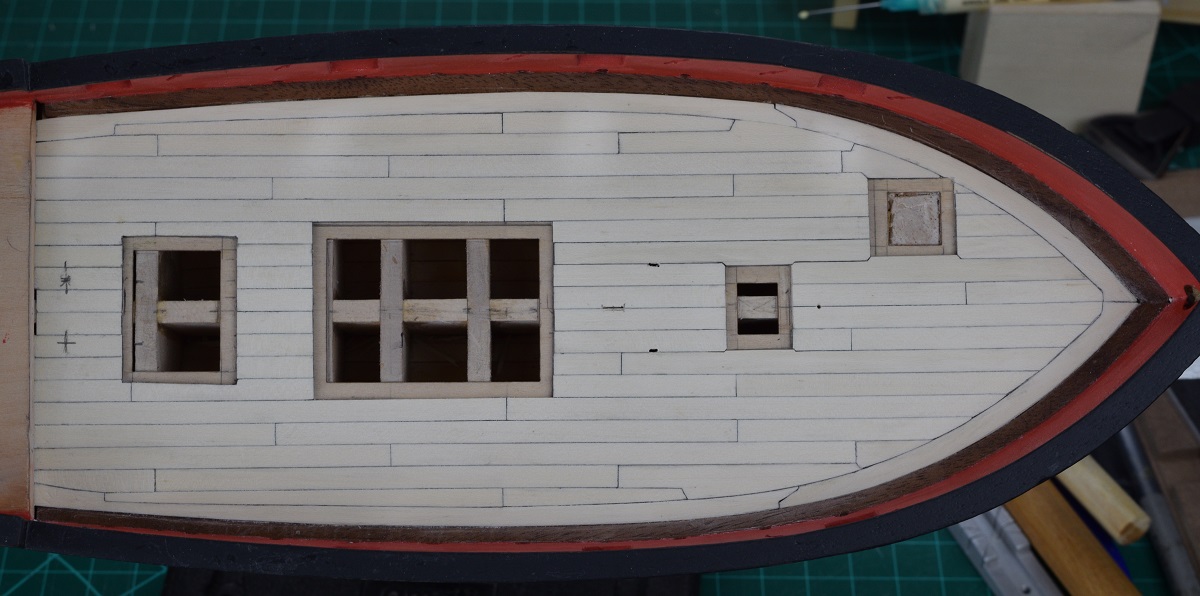 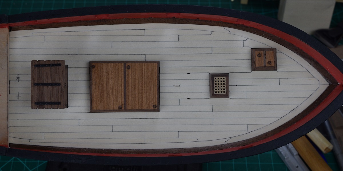 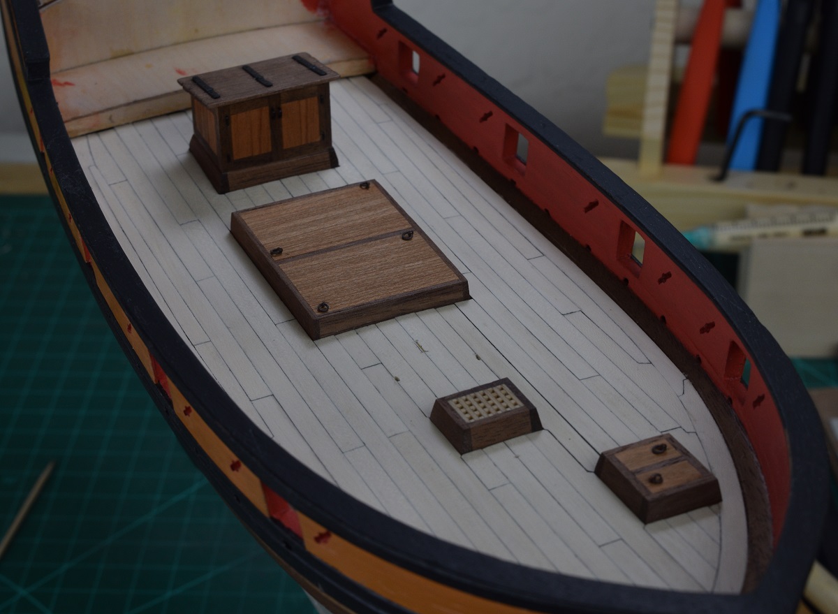 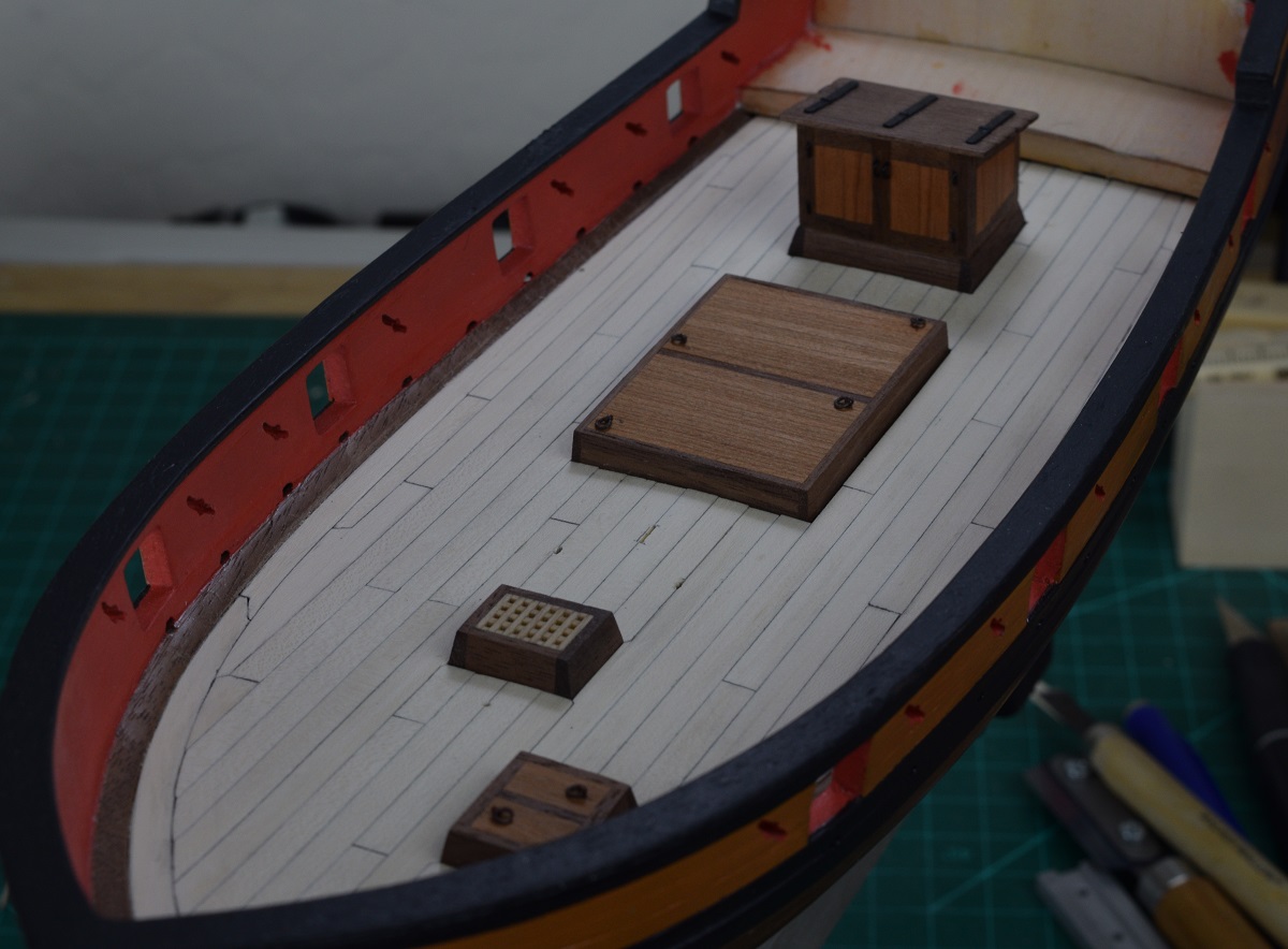 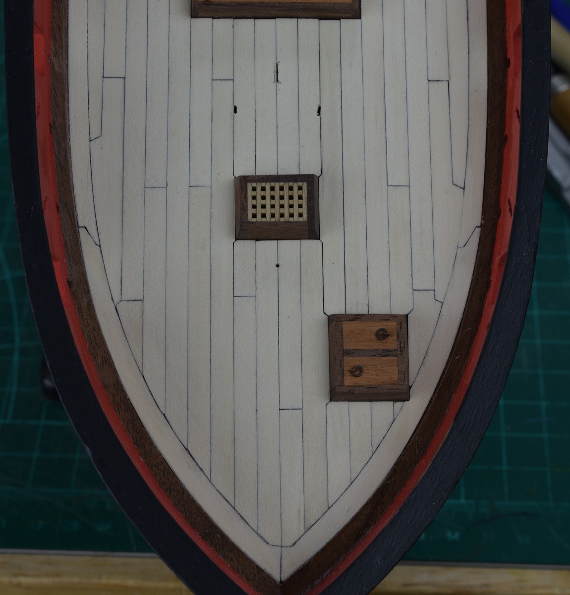 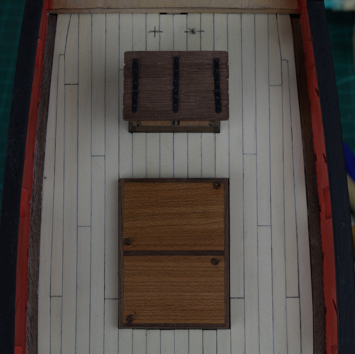
|
|
#
?
Nov 2, 2020 02:41
|
|
|
I've actually accomplished some more things on the AVS over the last few days, in the form of completing most of the quarter-deck. Today I completed the quarter-deck, and then began drilling holes. Ended up with 510 holes (I think), and only after it was completed and I was editing the photo's to upload did I notice that I missed a pair of holes on a butt joint. Oops. I also managed to knock one out on the quarter deck, so after the poly has dried I'll have to add the 2 missing ones and repair the one that came out. I got going on things and didn't take any in-progress photo's of the quarter deck, or the tree-nailing except for the first shot. SA Note: Tree-nails (also Tre-nails or Trunnels depending on who you ask) are the round spots on the planks where there is a wood plug placed to cover up the heads of whatever method of fastener is used to secure the planking to the framing underneath. The fasteners can be nails, rivets or bolts, but the holes are always plugged with wood plugs. Sometimes the plugs are obvious and sometimes almost invisible. I went for a subtle look. I drilled holes and then filled them with a wood putty. 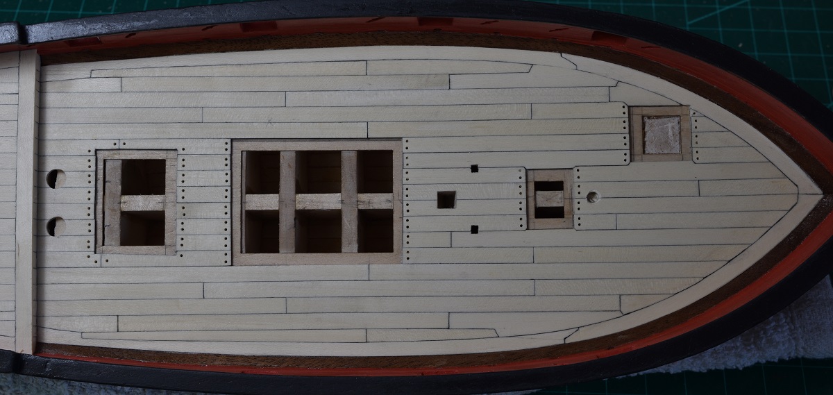 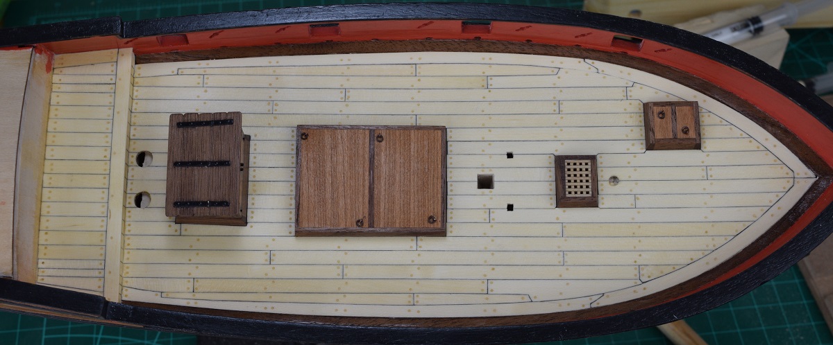 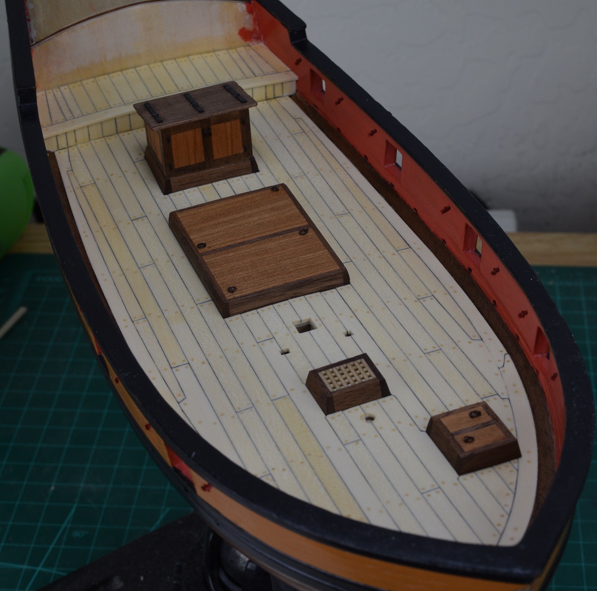 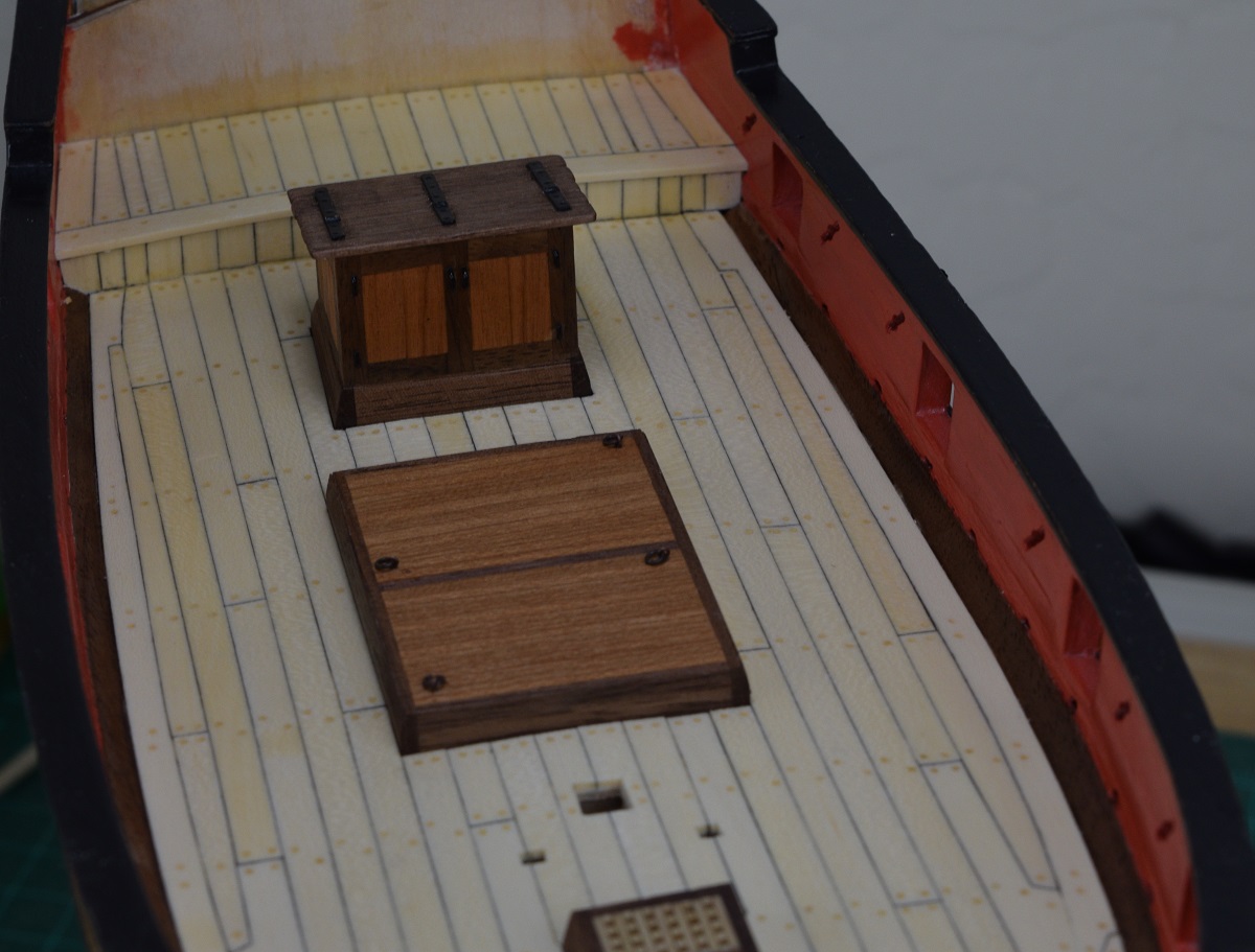 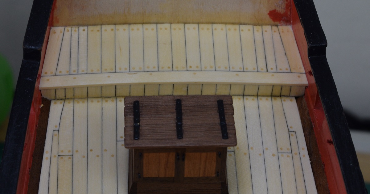 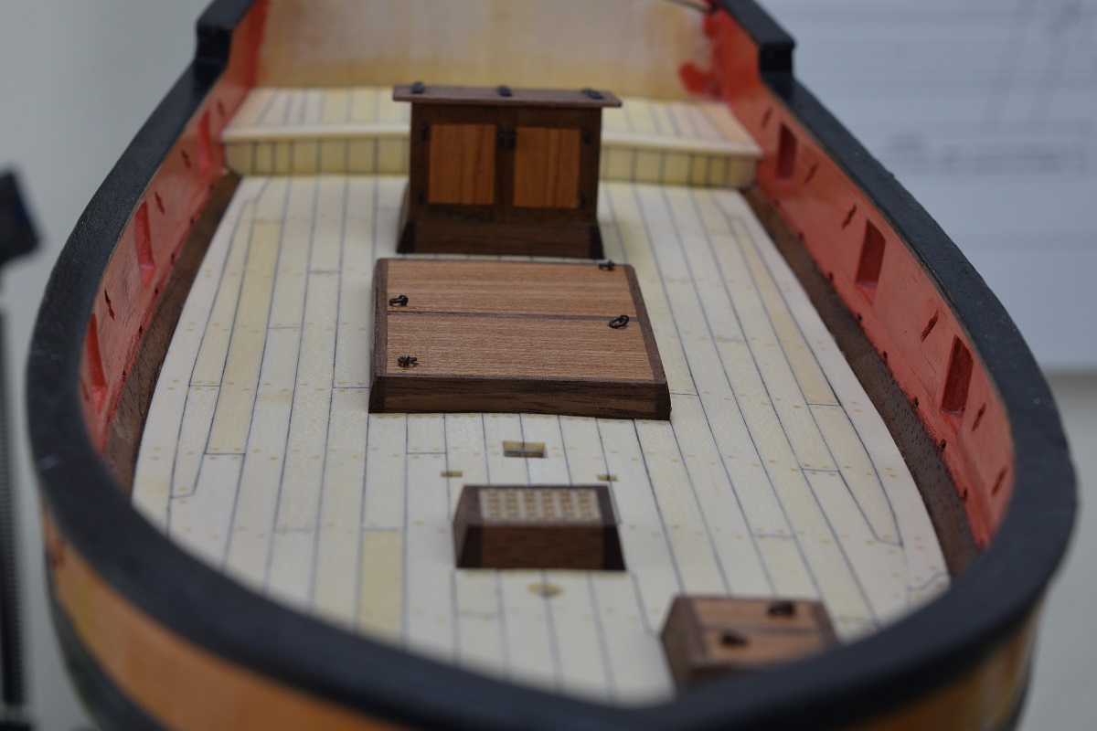 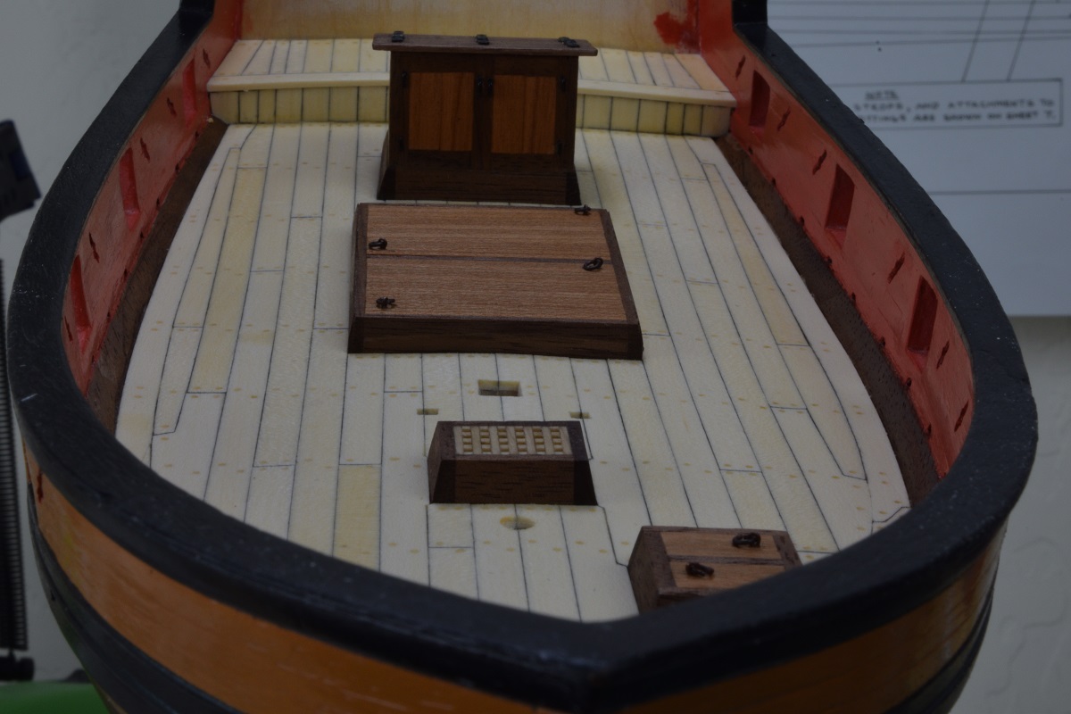 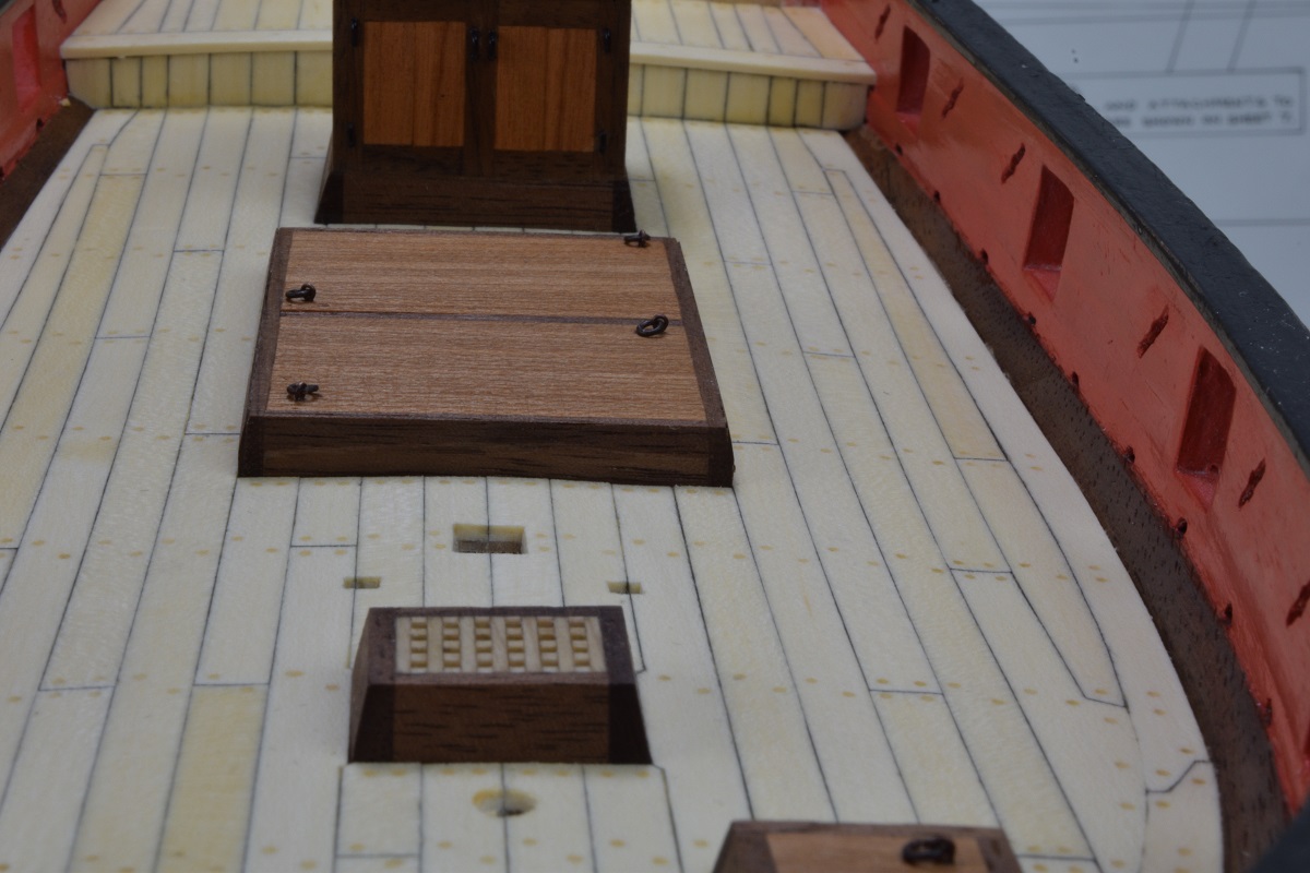 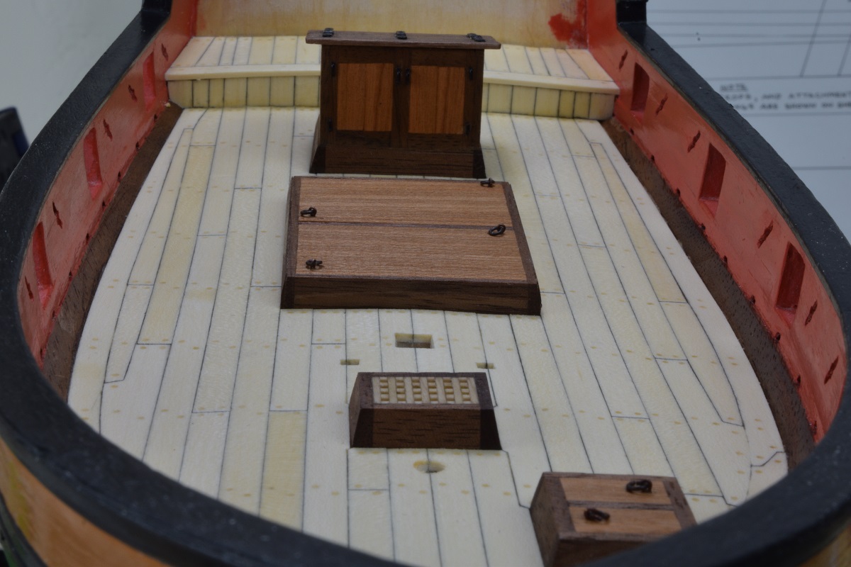 I got the quarterdeck wall mostly done. It still needs to be finished and have details added, but the wood is in. I am again using cherry for the door paneling. I do not have the base trim in yet either. 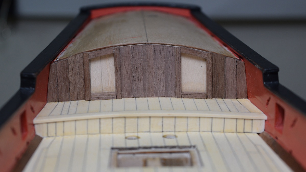 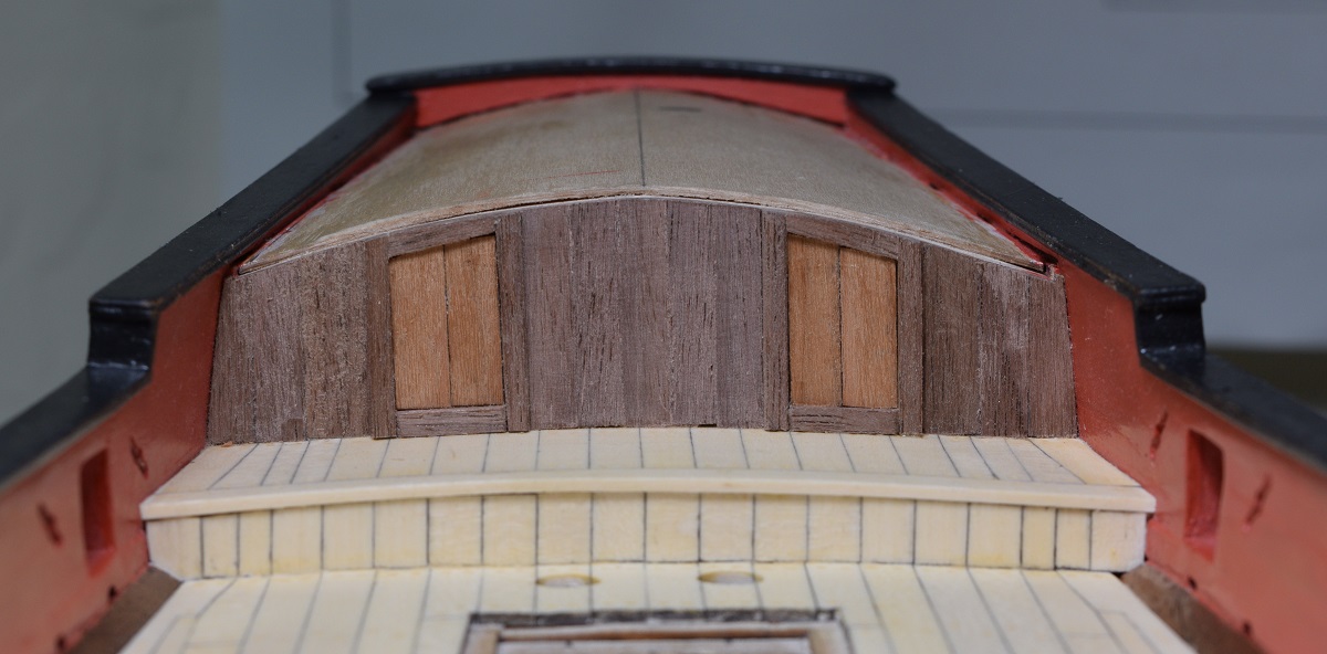 Few more details added as I continue to put off cutting the tapered planks for the poop deck. Added the bottom molding and the door handles and hinges for the quarterdeck wall. 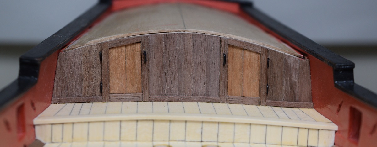 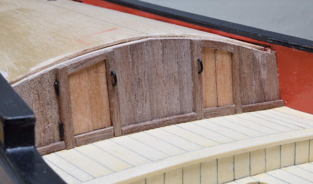 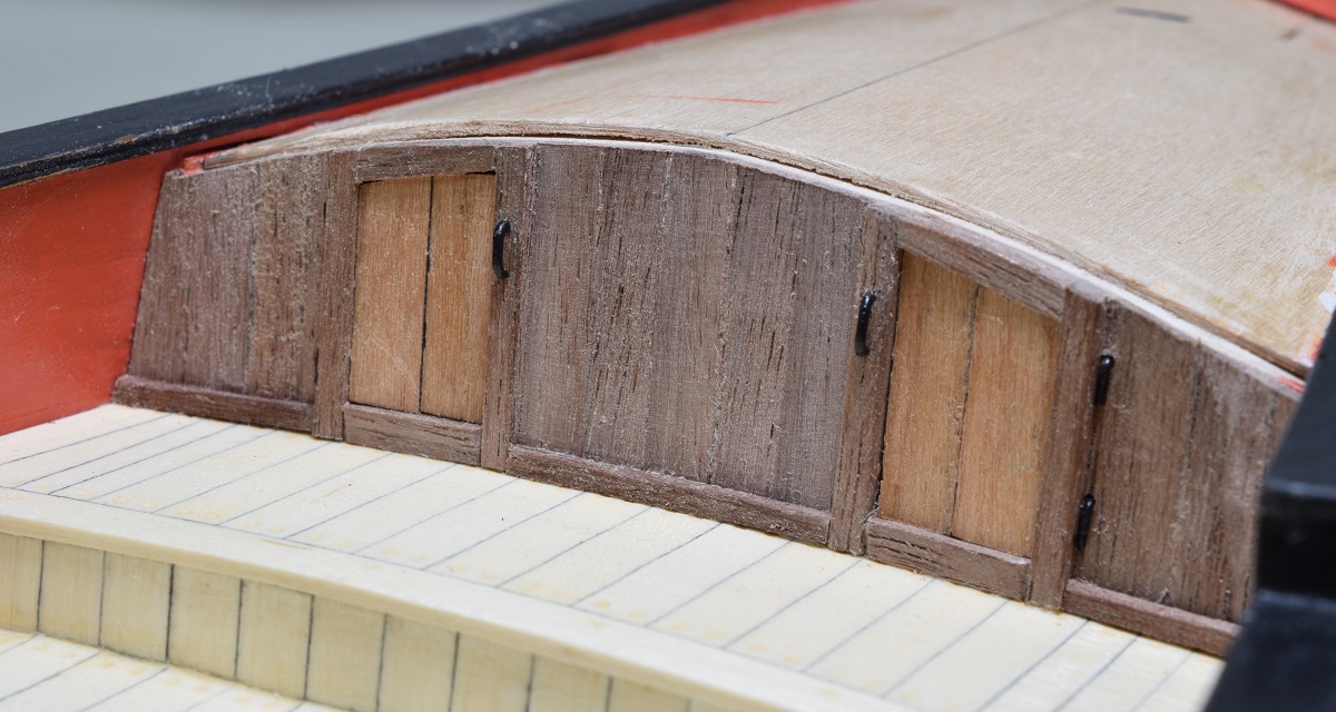 It's amazing how terrible the unfinished wood can look in macro photographs.
|
|
#
?
Nov 3, 2020 03:30
|
|
|
So the deck at the back of the ship is called the poop deck. The poop deck on this particular model ship is planked with long parallel planks, but since the deck is wider at the front than the back, that means that every single plank needs to be wider at the front than the back. Yay! I found a very simple jig in another AVS build log that works quite well for making the planks so they don't have to be done completely by hand, 26 times. First up, I cut 28 pieces of plank to the appropriate length. I use a simple jig that I made to cut the hull planks to 4", and just measured and cut a new slot for cutting these planks: 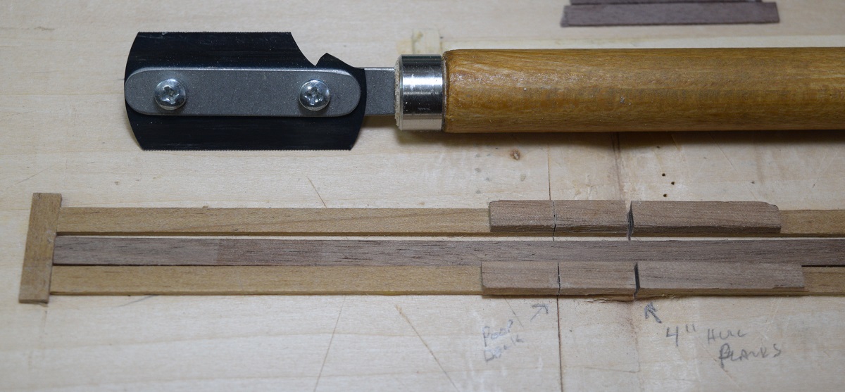 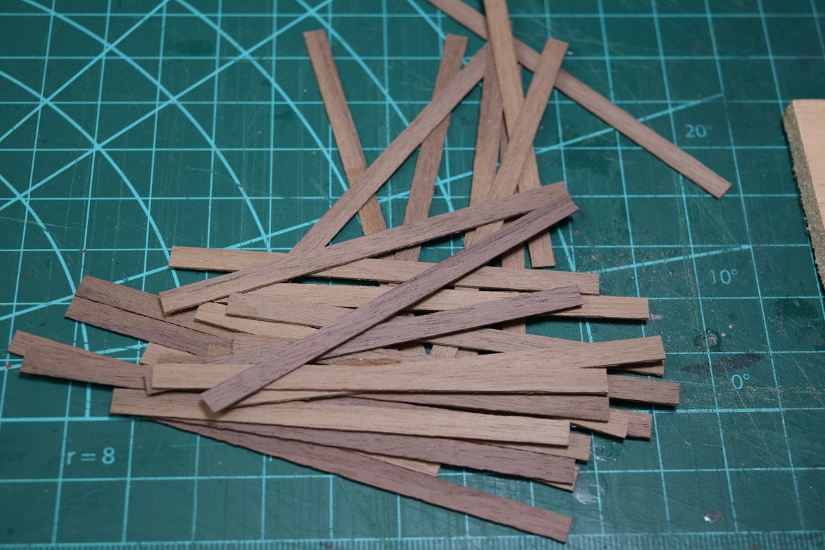 The angle jig is surprisingly simple, but I don't think I would have thought of it if I hadn't seen it in another build log. I apologize for not giving proper credit, but I can't seem to locate it again right now. The jig is made up of a 1/4" piece of wood that the deck plank lays against, 2 x 1/4" end pieces which are cut to length (sanded to final length after glue is dried) to give the proper taper, and a couple pieces of .030" (deck plank thickness) of planking placed to hold the deck plank in place, and also to support the straight edge used for cutting. 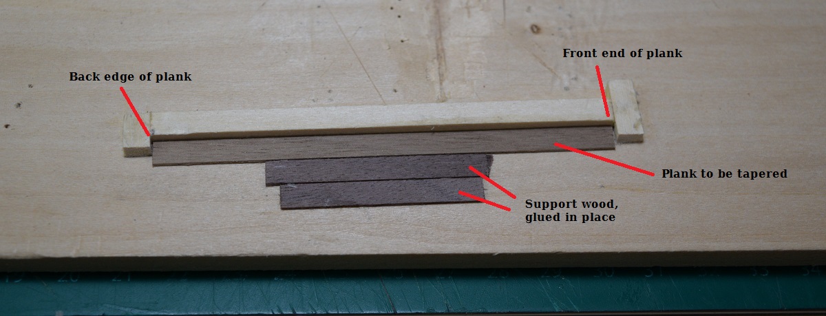 Place the plank into the jig, hold a straight edge up against the end 'stop' pieces, and then using very light pressure on the blade, simply cut along the straight edge to make tapered planks. I used a very thin steel straight edge for the actual cuts, the clear plastic one is for the photo only to show how it rests on the support planks. 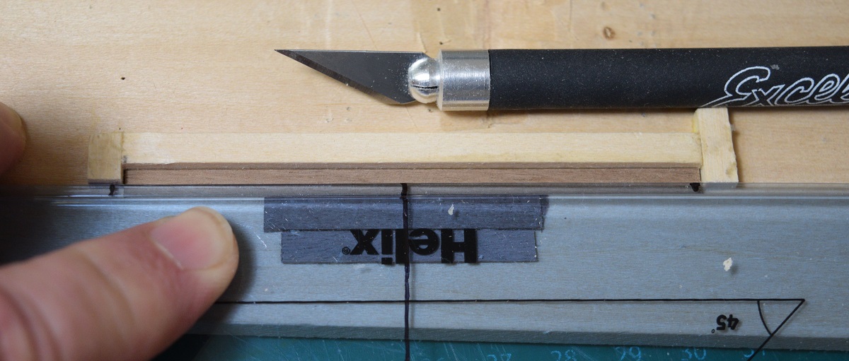 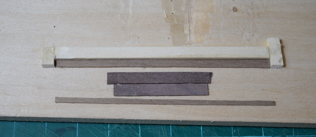 Then, start placing planks! 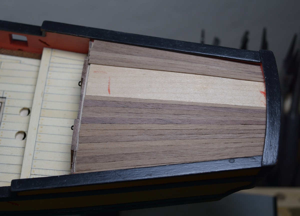 Didn't take any other in-progress shots, it's just normal planking, but care must be taken to bevel the edges, as the curve of this deck will cause significant gapping if the planks are left straight edged. Once complete there is a ledge left at the front end of the deck. 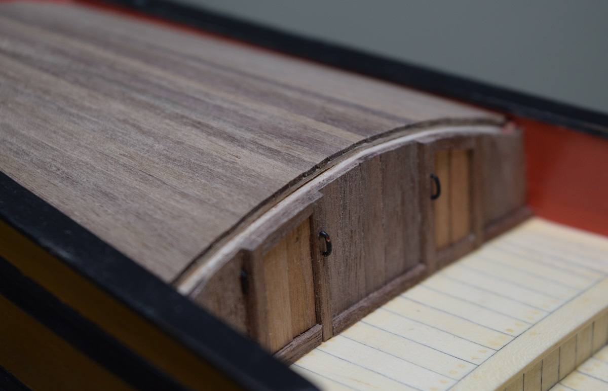 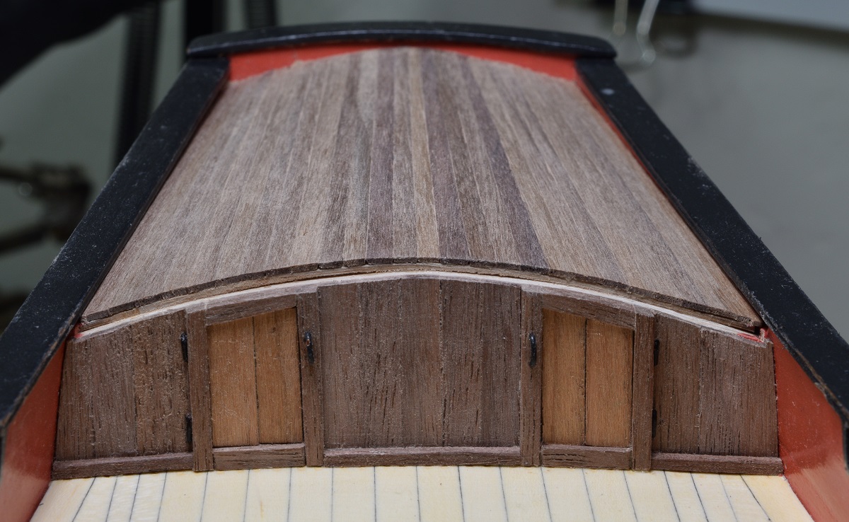 This ledge is a place for a moulding to go, which is supposed to be made out of walnut. However, I happened to have a piece of swiss pear that was almost exactly the right dimensions to make this moulding, so of course, I had to try it. I used a heat gun and pre-bent the curve into the wood so that it laid evenly all along the top edge of the deck, and then I beveled the back, and rounded the front. I also used a very sharp 2mm chisel to fine tune the front edge of the deck until I was happy with the fit along the edge. 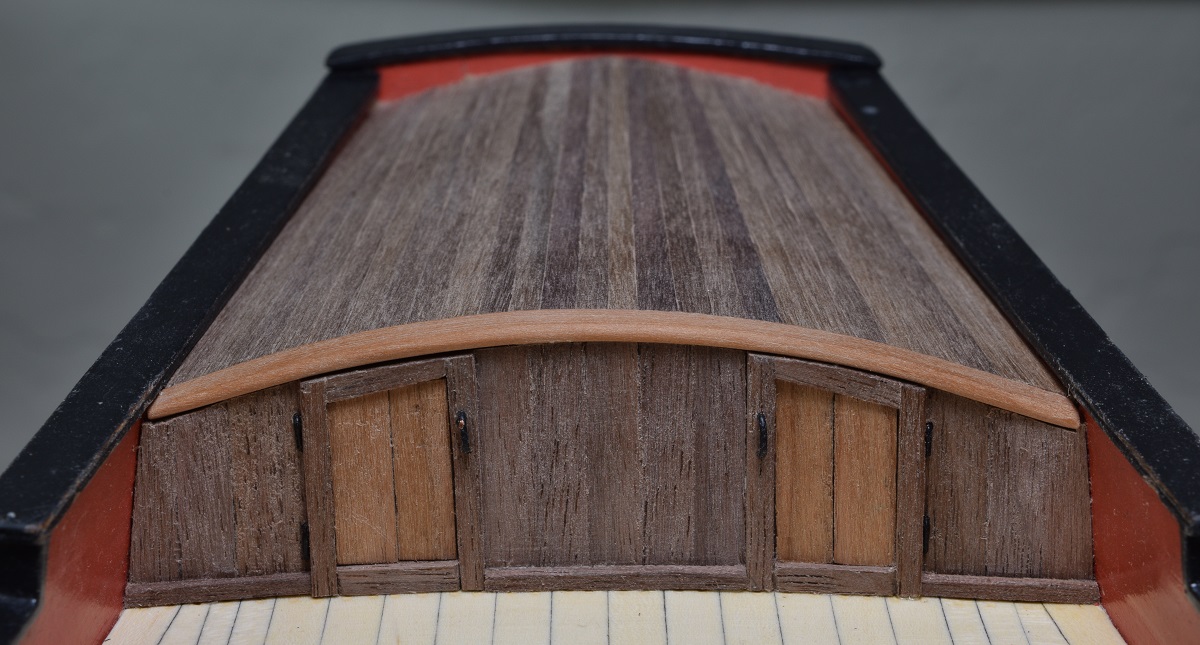  And finally, I sanded to 320 grit, and applied a coat of wipe-on poly which is still drying in this photo. 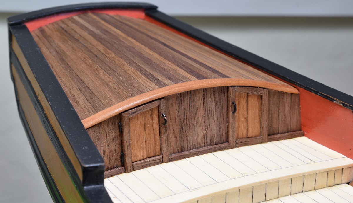 There are some fitment/gap issues along the top edges on both ends of the quarter deck wall, but I don't really see any way to fix them as they are built into the ship from mistakes made earlier in the construction, so I'm just going to move on and hopefully they won't be very noticeable after the ship is finished with so much other stuff to catch the attention of the observer. -------------------- Next up was to begin working on the gun carriages, for real this time. Due to a huge amount of work at the job that pays my bills, I was only getting one of them done every few days. So really really slow. First I assembled one to make sure that the slightly larger than the kit carriages from Syren would work ok. 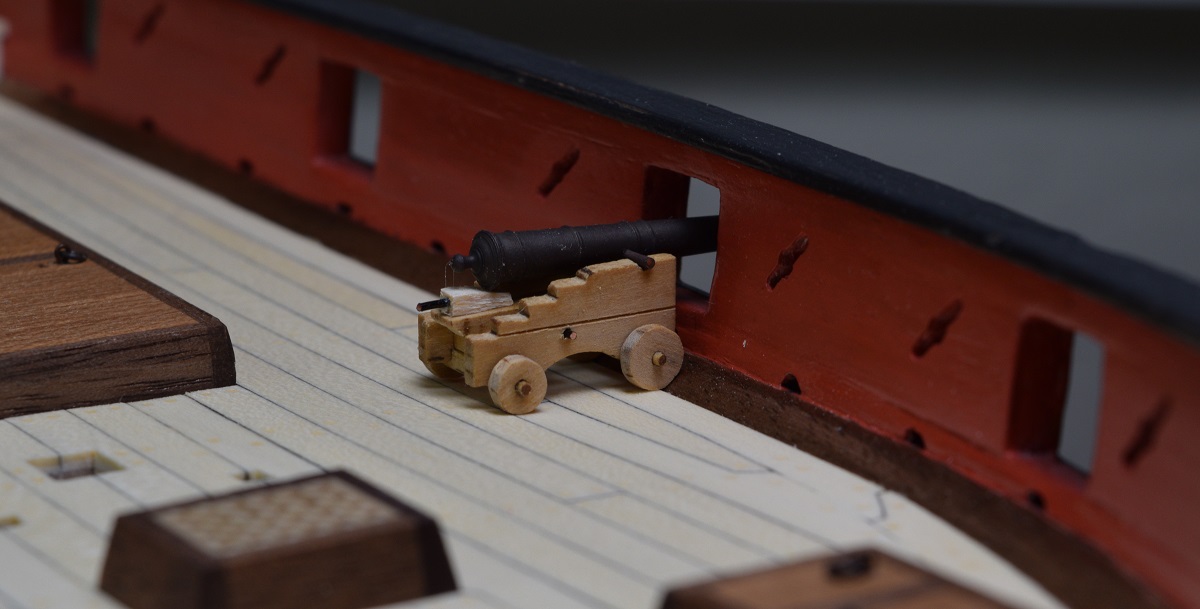 Looks fine to me! Of course after this it occurred to me that a smart person would have painted the parts before assembly. I finally got an air compressor, so I laid out the rest of the parts and primed them. New toy! 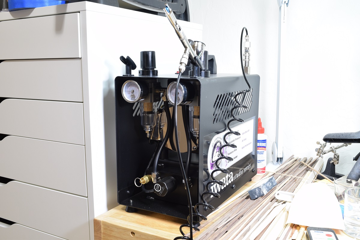 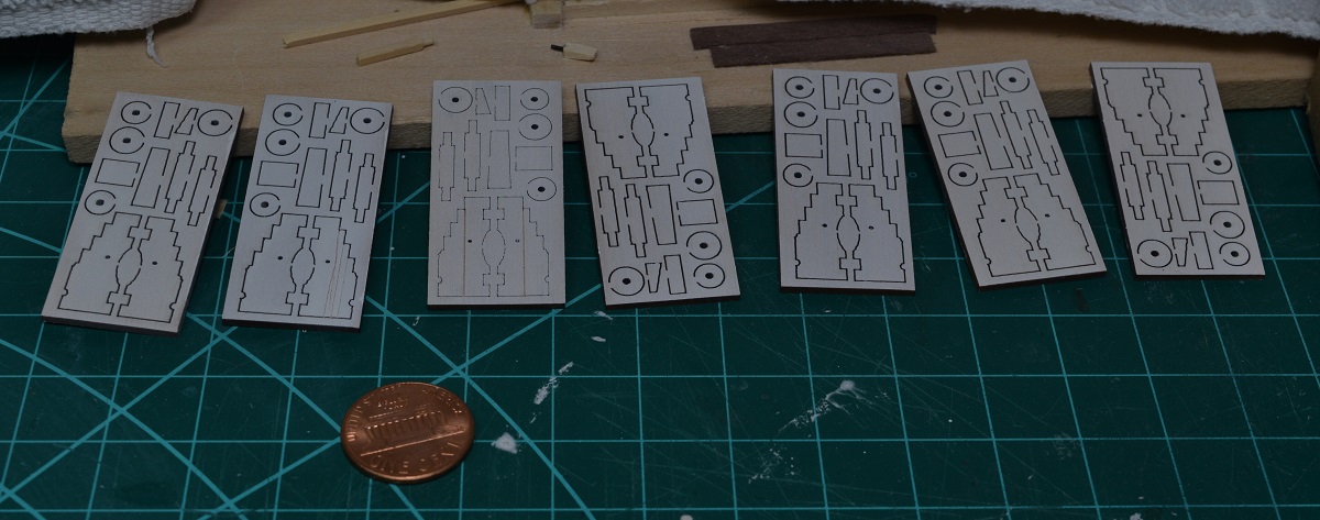 I then painted them all, but didn't take any photo's, and began assembly. Late in the assembly process I did snap a couple pictures, but they are mostly pretty boring. 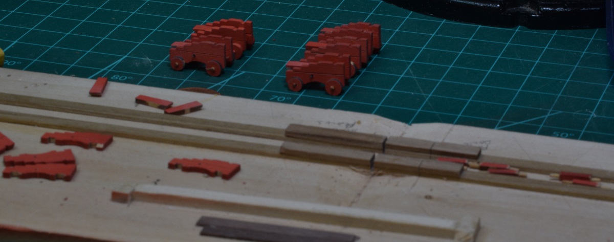 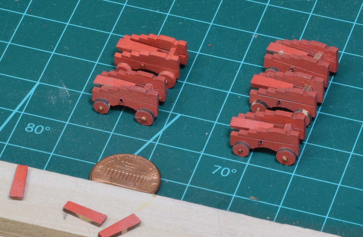 I got carriage #6 done finally, so I figured I'd stick them on deck and see how they look. No quoins, so the barrels are a bit high in the gun ports. 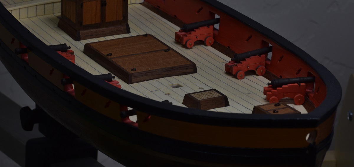 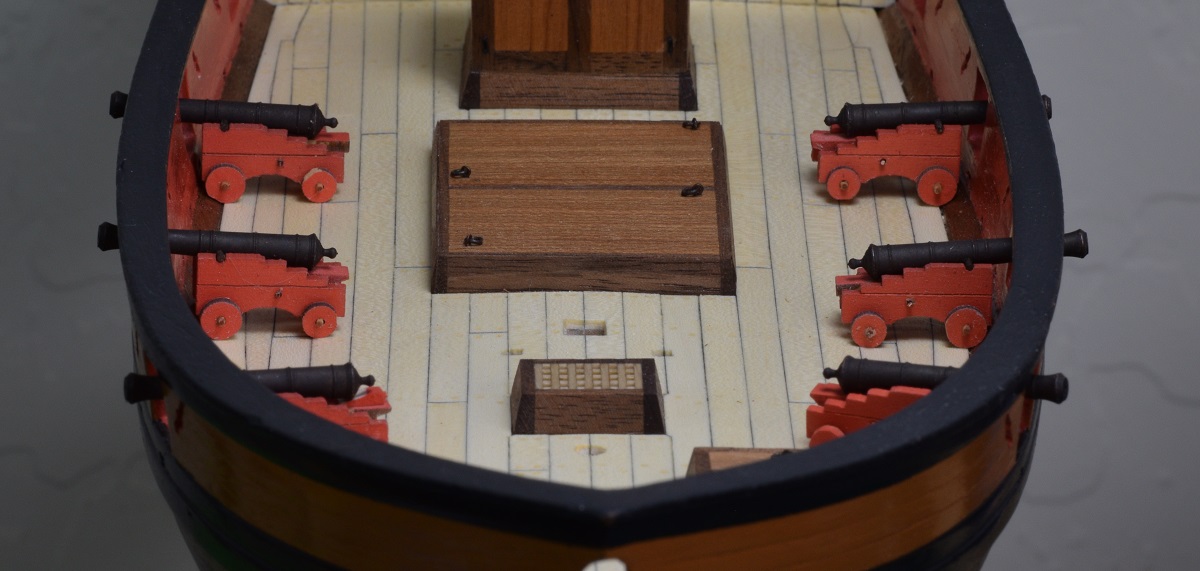 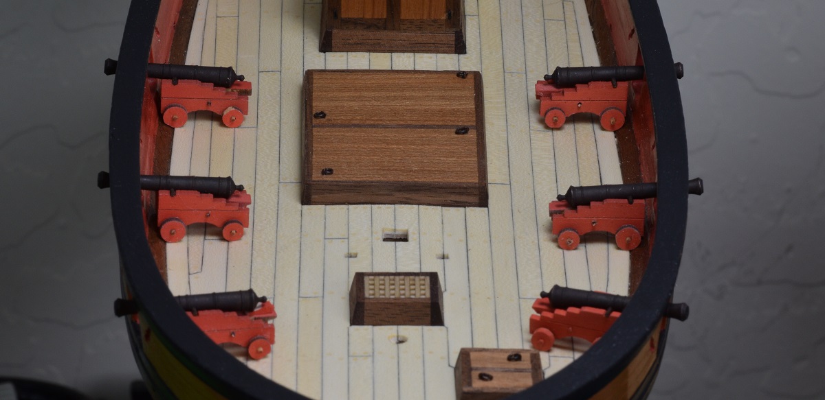 Lots of work still to do on these, I have to respray them to get the parts without paint covered, make the quoins, add all the eye-bolts, then make the caps to hold the guns on, glue all the various bits in place and do paint touch-ups, etc. Oh, and I also need to complete the finish on the hull & deck, right now there is only a single coat of poly on everything, and I need to buff that and add another couple of coats before I start putting stuff on the deck that will make it difficult/impossible to do later on. But, it's good to see at least a tiny bit of progress after the almost 2 months since I finished the poop deck.
|
|
#
?
Nov 5, 2020 05:12
|
|
|
The learning trials of ship-building continue. Each little gun carriage gets 5 eye-bolts, which means I have to drill 5 little tiny holes (#78 drill). I started with a pin-vise and I discovered rapidly that the boxwood which these carriages are made out of is a LOT harder than the basswood I've been drilling before, and it took 10 minutes to drill one hole through the side of a carriage, and I had 29 more holes to drill. Ugh. Then a lightbulb went off and I remembered that a friend had gotten me this really awesome collection of little drill-bits that were very sharp but needed to be used in a press, since they are very hard/brittle. Well, I don't have a drill press yet, but I did just recently get a little Proxxon mill, so I chucked up the #78 bit, and then clamped the first carriage in the tool-bed vise. So awesome, got the 29 holes done in less time than the first one, and they are much more precisely located than they would have been.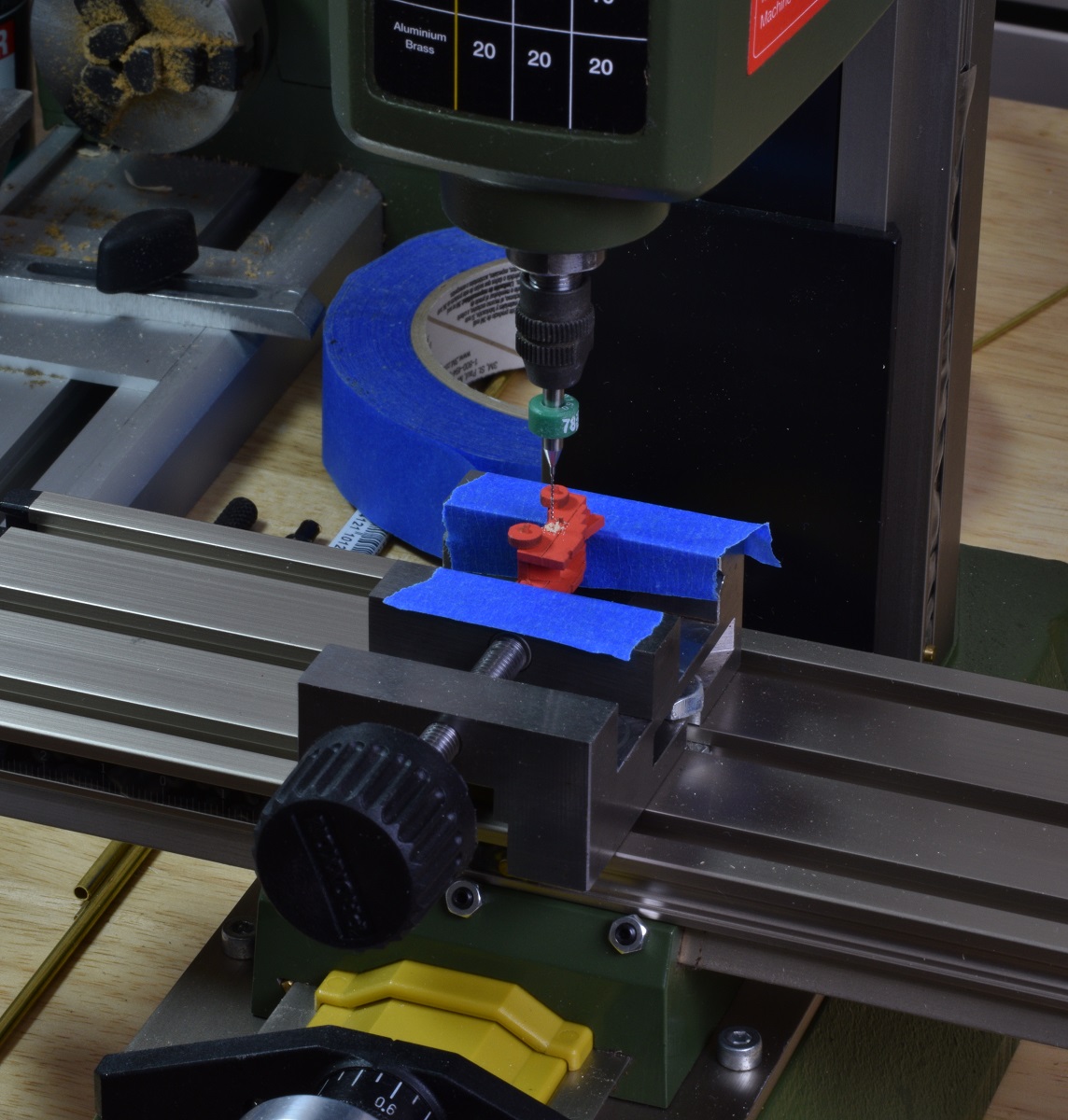 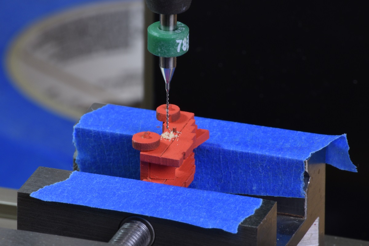 Next up, I cut down the eye-bolts and glued 3 of them into each carriage. The other two for each carriage get a ring that the breech line will go through later on when they are rigged to the deck. These eye-bolts and rings are tiny and I ended up doing all this work wearing an optivisor magnifier thing. 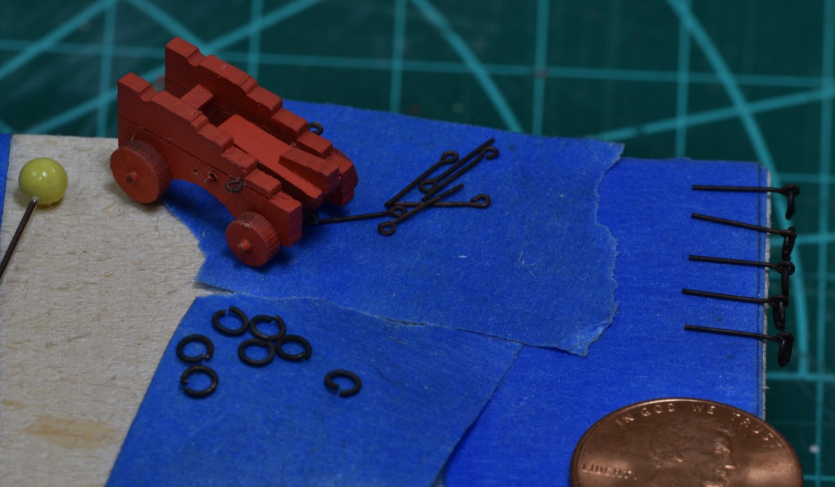 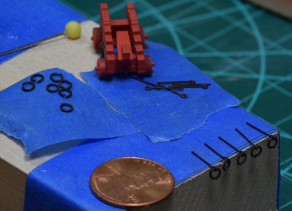 I assembled all of the rings to their eye-bolts and used a tiny drop of CA glue to join the ends of the ring. Probably didn't need to do that. Then I decided to just finish one gun assembly because I wanted to see it done. I used very small strips of manila folder to form the trunion caps. These were supposed to be made out of brass, but I made both brass and the paper ones, and the paper look better as I can't seem to get a nice smooth curve out of brass at this small scale. I put in the eye-bolt / rings on each side, added a handle to the quoin, and painted the rims of the wheels black to simulate iron bands. I was planning to add some more bolts and other details, like the retaining pins on each axle, but these things are so small that I decided I wasn't up to the task, so I think this is how the guns will all be completed, other than some clean up and touch up painting later on. 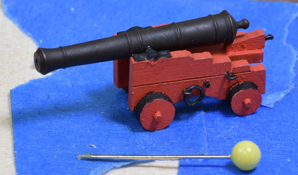 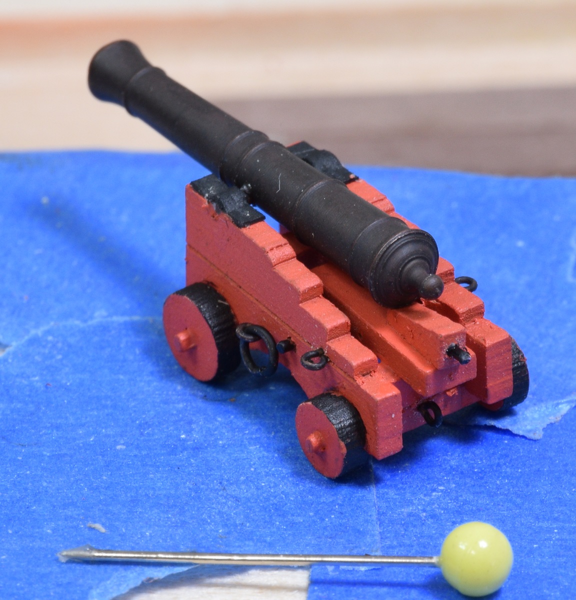 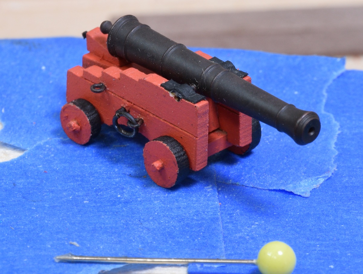 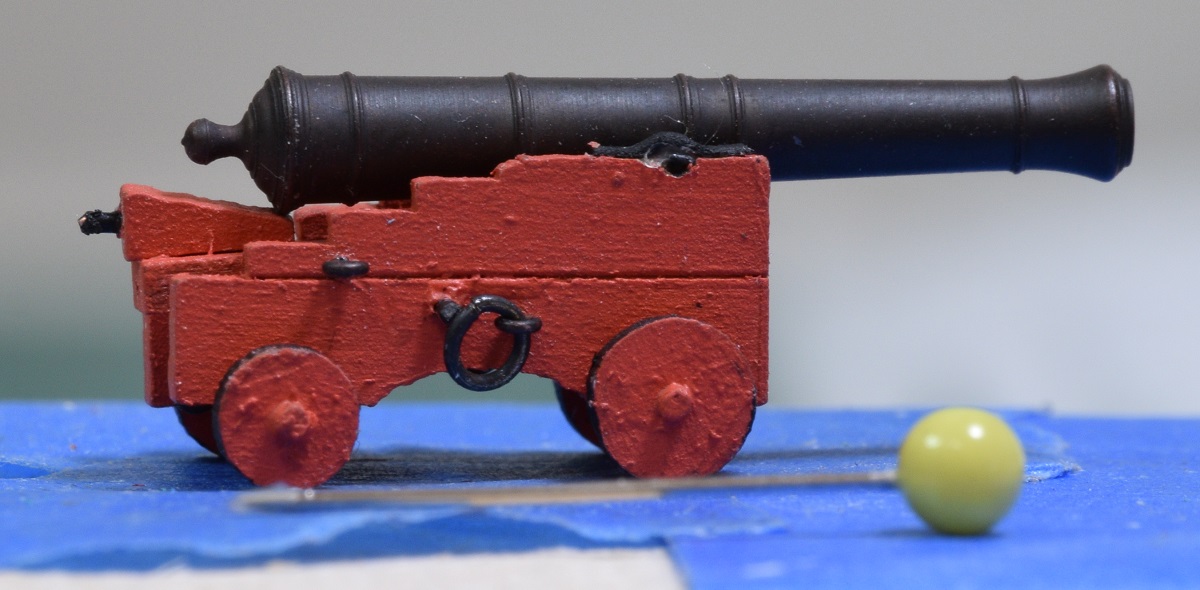 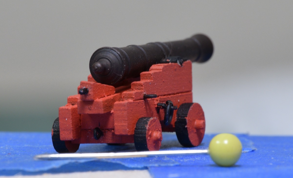 The paint looks really rough zoomed in this close, but even 6" away with my naked eye it looks smooth. Macro photography is both a blessing and a curse. I finished up the rest of the guns, and did some touch up painting on all of them. 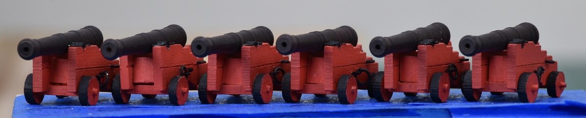 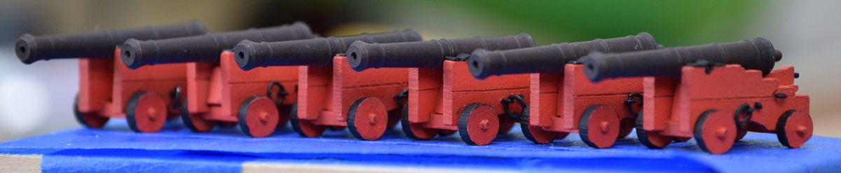 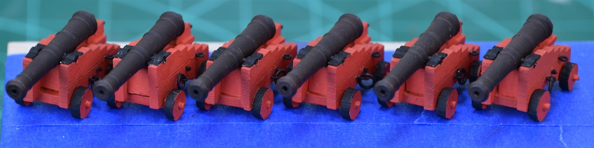 Next I tackled the rudder. I completely forgot to take any pictures of this in progress, but it starts out as a laser cut walnut piece with no taper. To make it into a proper rudder, first it has to be tapered front to rear (it's about 1/2 the thickness along the back edge as it is at the front), and rounded at the front. Then the lines have to be measured out and etched. This is to simulate the fact that a real rudder wasn't a single piece of wood, it's built up out of multiple timbers. In this case 4 pieces. Next I have to cut recesses for the pintles. This was accomplished with a very sharp, small chisel. 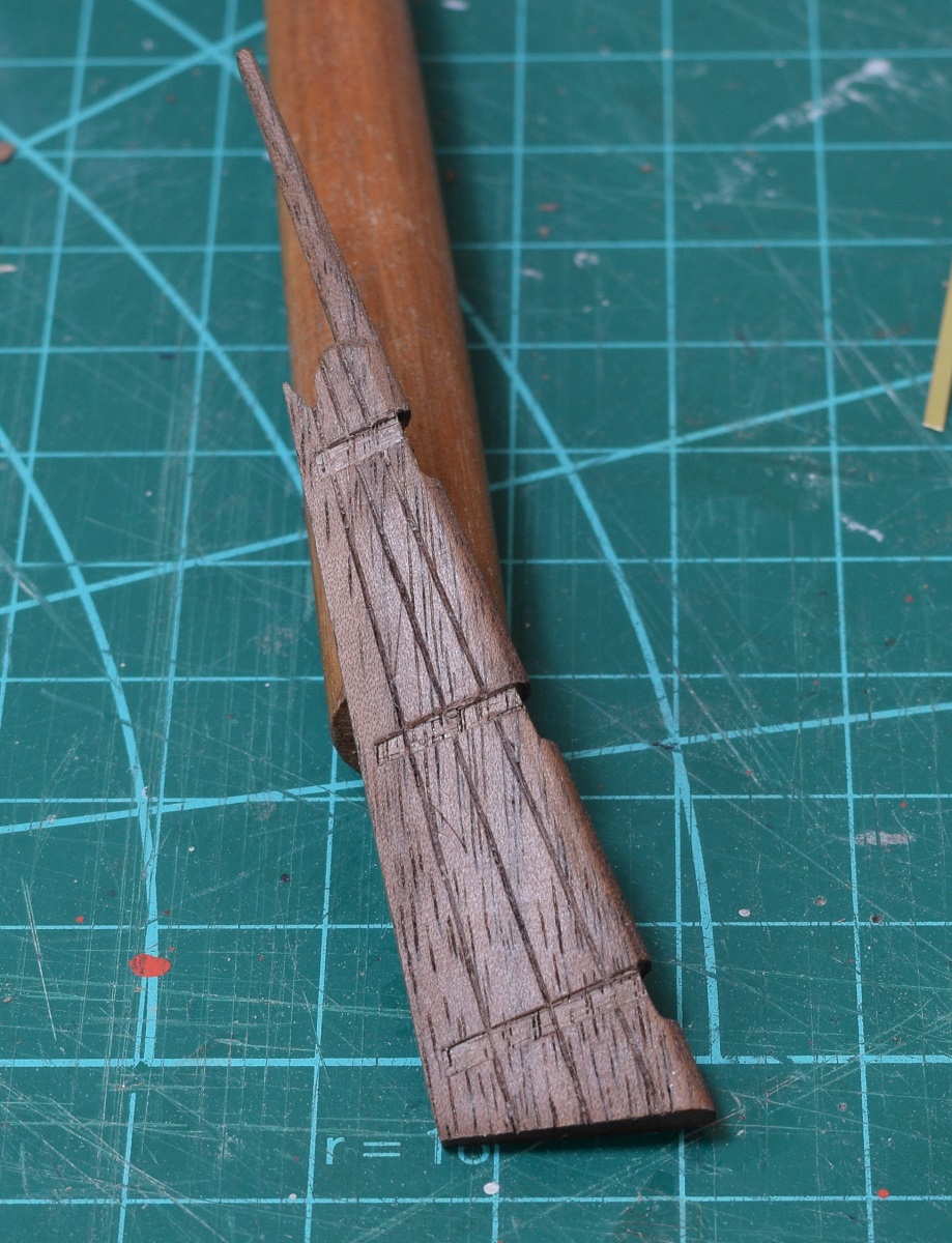 Next up, I got to learn something new! Soldering. I've soldered a lot of electronics before, but by before I mean 30+ years ago. Soldering brass using flux, silver solder, and a torch is all new, but for my first effort I think it came out ok. I made the pintle - brass pin soldered to the strap that will go into that recess I cut into the rudder. The hinge/pivot points on a ships rudder are called the "Pintle" and the "Gudgeon". The pintle is the part that goes on the rudder, the gudgeon is mounted to the sternpost on the ship. 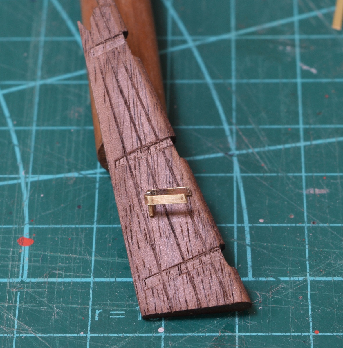 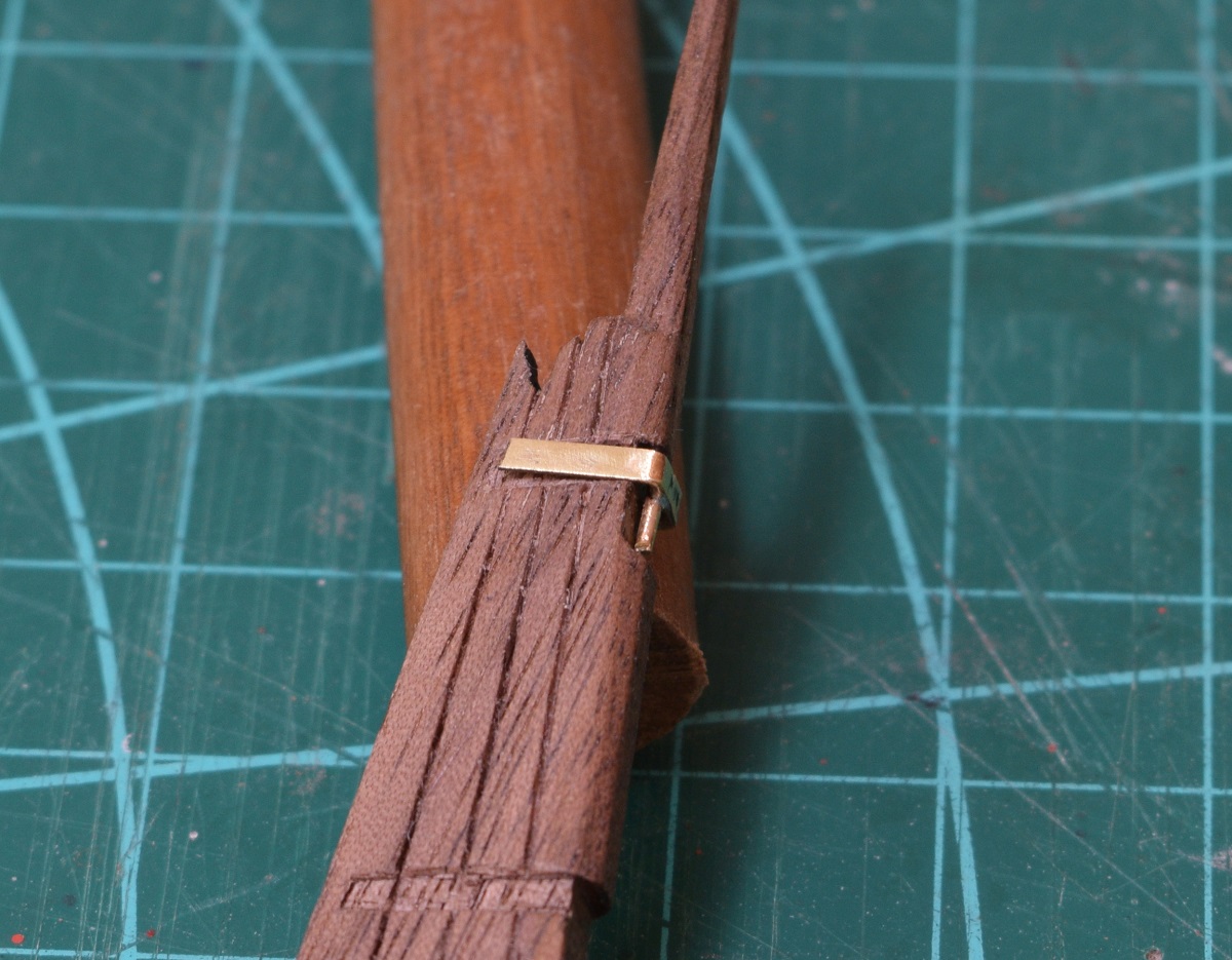 The plans make the gudgeon (the strap that the pintles drop into on the ship side) by simply using the brass strap, and letting the pintle drop into it. I decided to solder a tiny brass tube onto the gudgeon to make them work like a real one would. 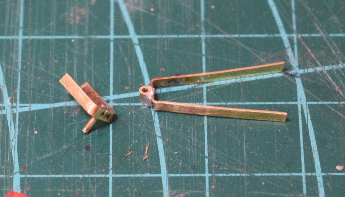 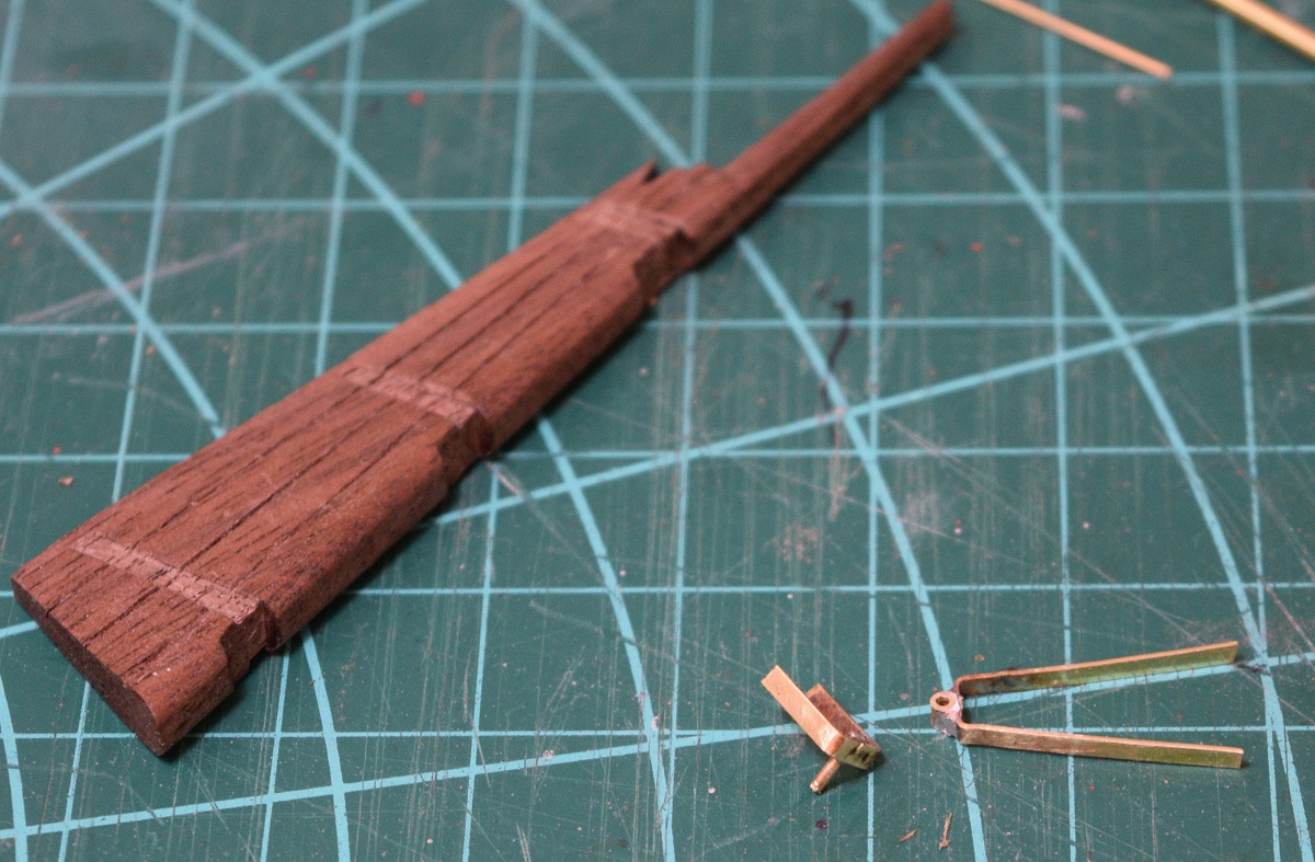 The pintle is too long currently, it will be trimmed later. 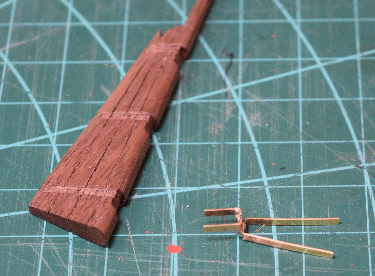 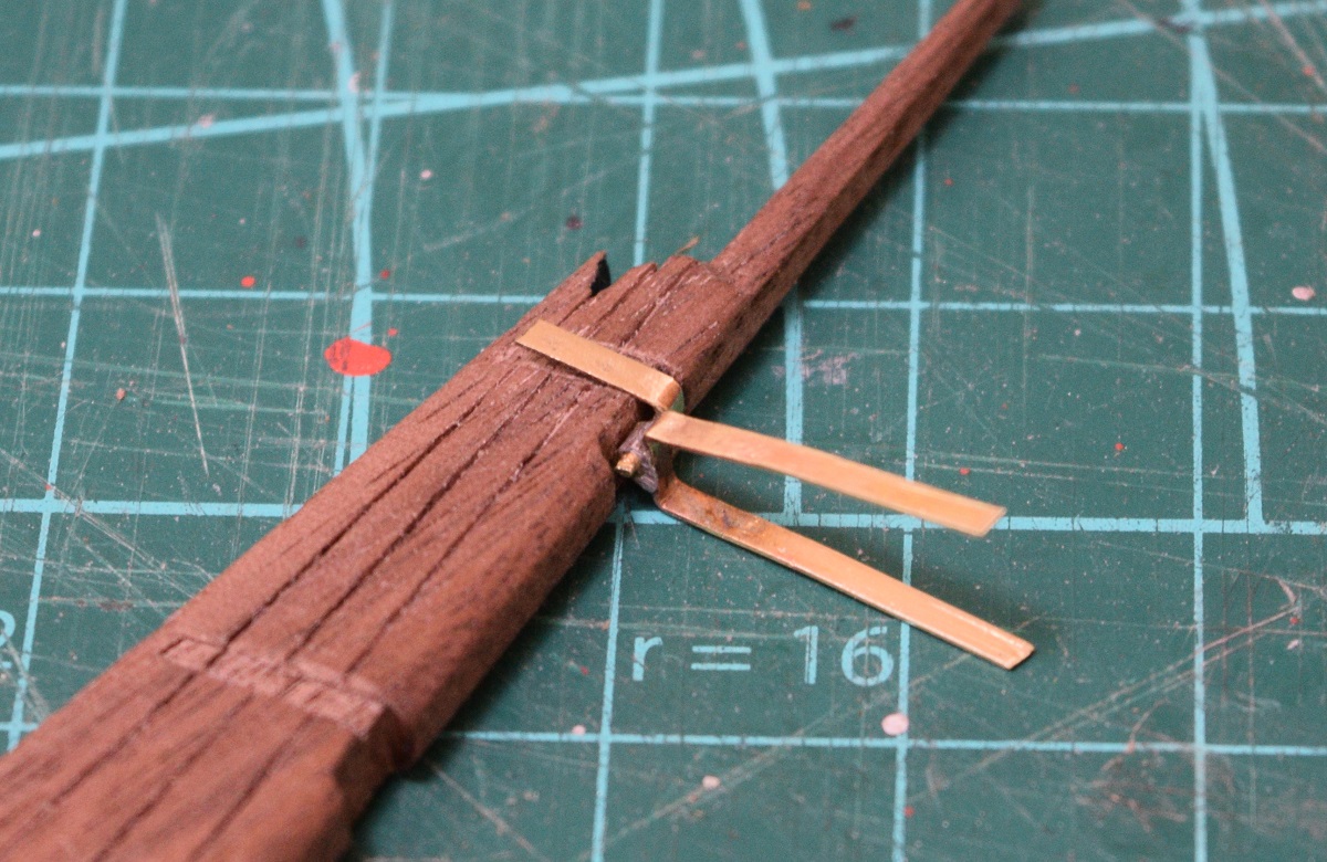 In theory the way I did this will let the rudder swing. In practice, I'll see how it goes when it's assembled to the ship and decide whether to use glue to 'fix' the rudder or not. Since the ship doesn't have a through tiller, and I didn't build it to allow the ships wheel to actually turn the rudder, it really isn't of much importance to me whether it will end up movable or not, but I was interested in building it this way because I've seen other logs done this way and I think it just looks much neater than simply dropping the pintles into the brass band of the gudgeon without any sort of receiver for it (that's how the kit is designed). Now i just need to make two more sets of pintles and gudgeons, but my eyes are bugging me so that will be for another session. ----------------- Oh yea.. I bought a little tiny mill because I've only spent like 10x the kit cost in stuff and that's clearly not enough. 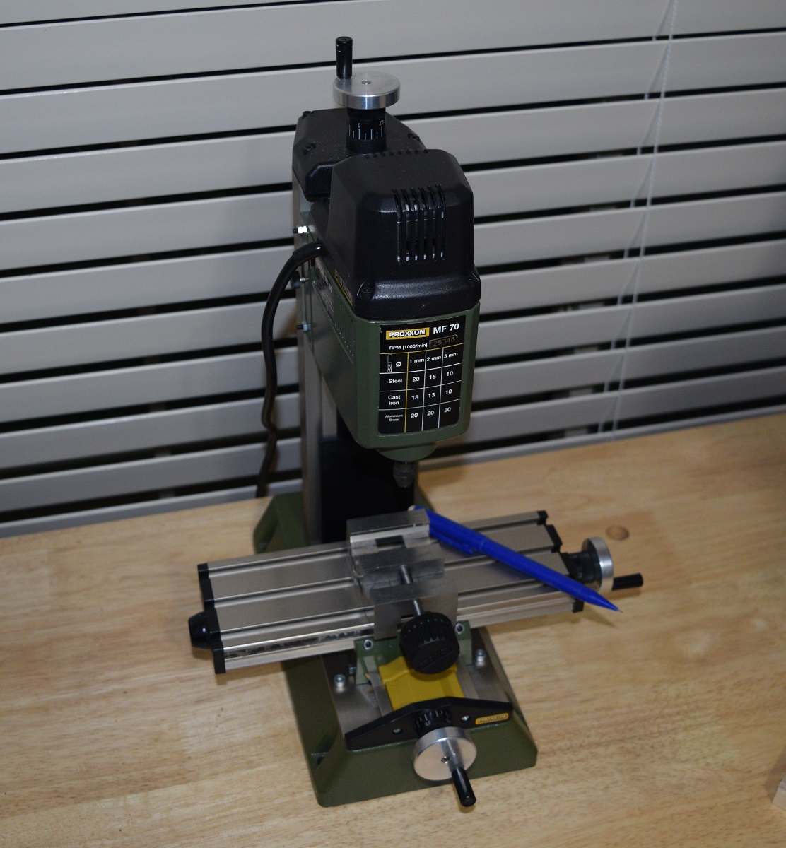 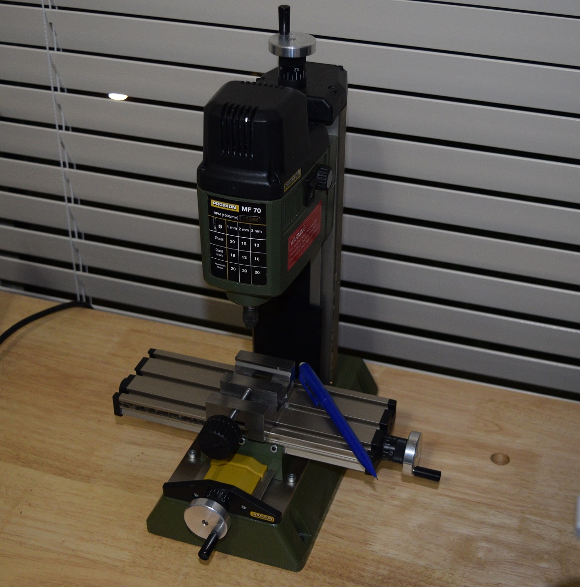 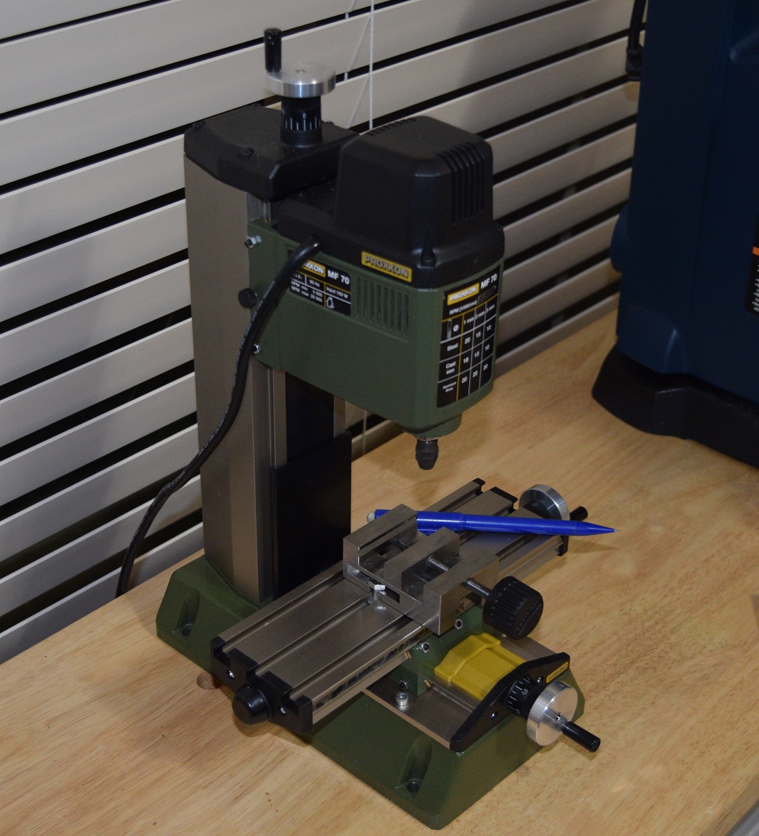
|
|
#
?
Nov 8, 2020 05:41
|
|
|
Finished all the pintles & gudgeons to mount the rudder, and then glued them into the rabbet's I cut for them in the rudder. Then I used a small drill and drilled indents into the brass to put tiny drops of glue to simulate bolt heads. 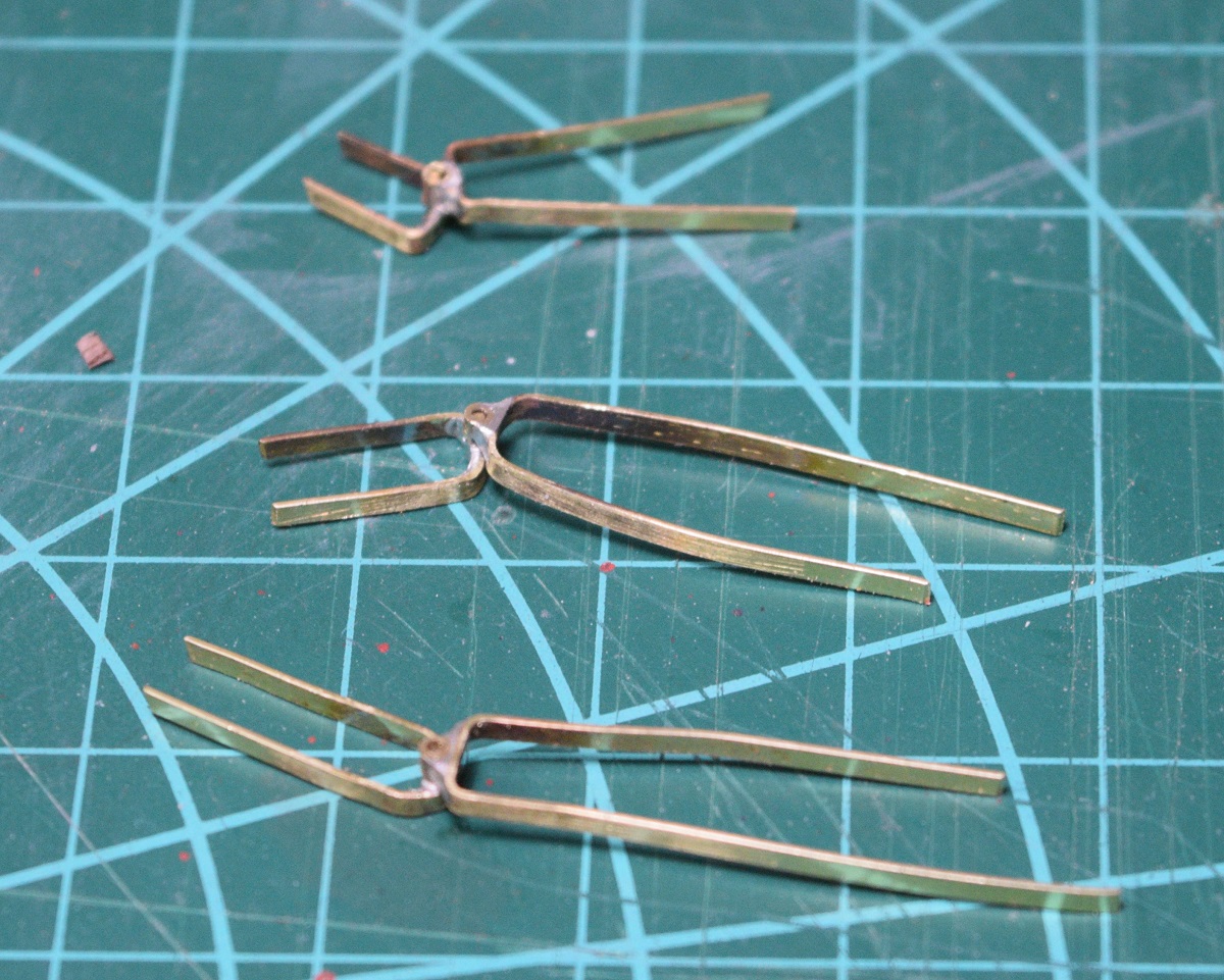 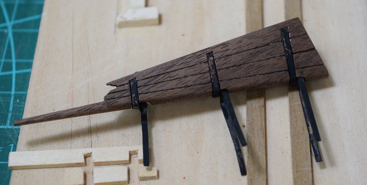 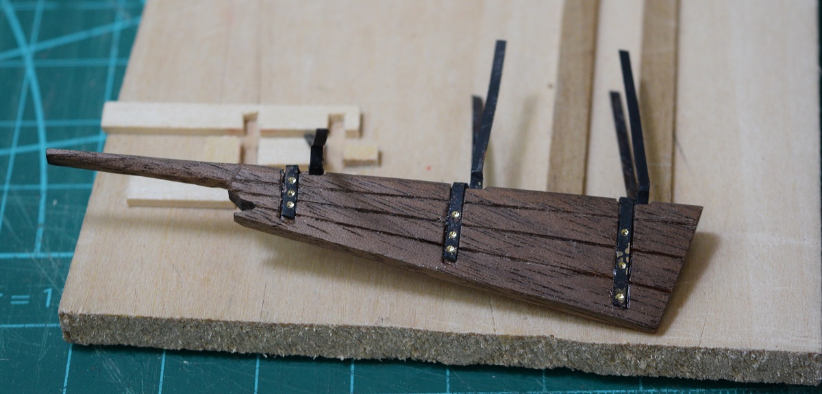 I forgot to take pictures of the in progress of that part, but it's not very interesting anyway. Today I mounted the rudder to the hull. It actually turns! 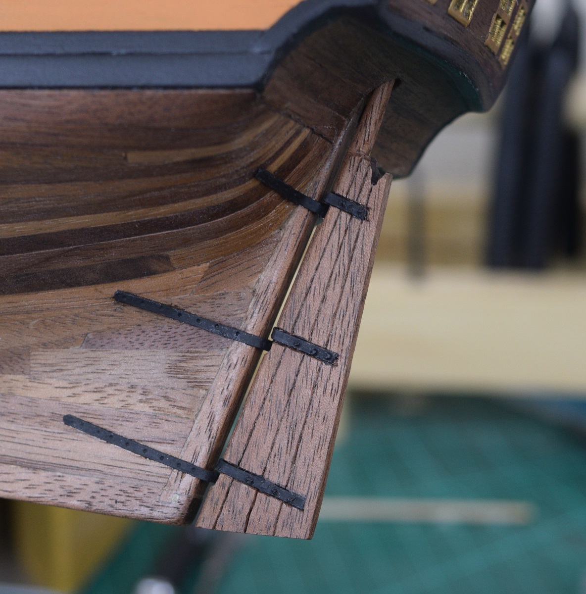 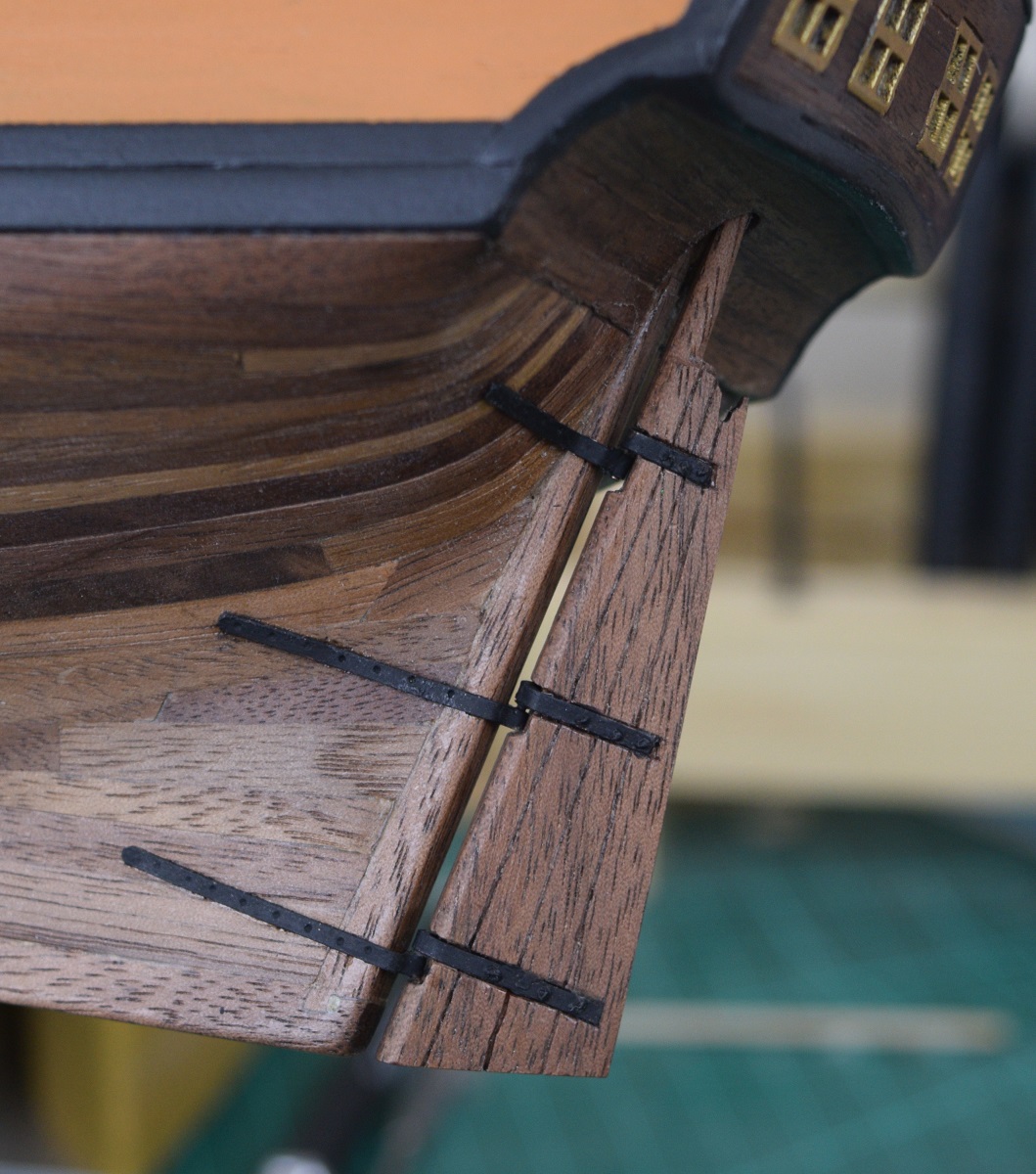 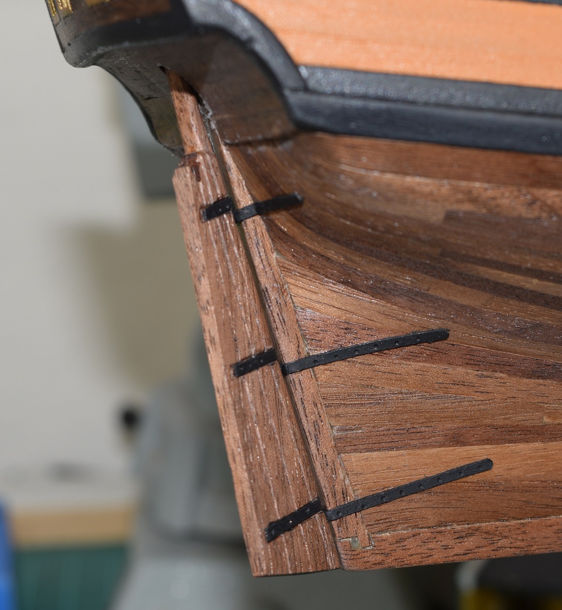 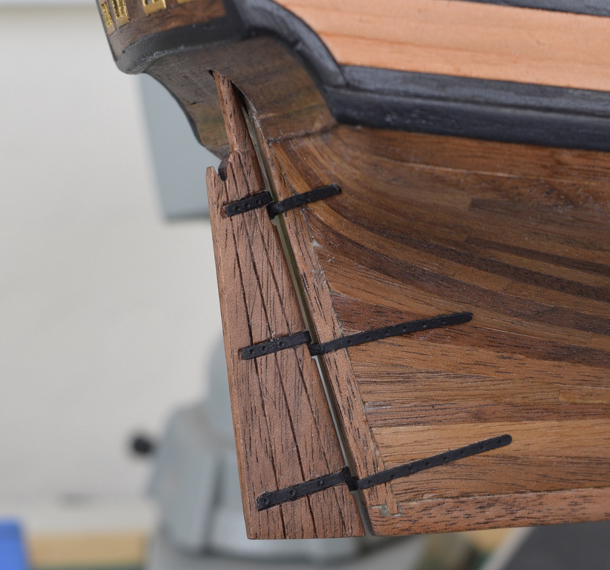 Next I move back to the deck, but before I can finish up all the various things that go on the deck, I need to mount all the eye-bolts and cleats while there is nothing in the way. The kit supplies white-metal casting cleats, and they are kind of ugly and I hate working with them, so I decided replace the cleats with the boxwood ones from Syren. I have finished one of them, and I haven't counted, but I think I need 30+, so this will take a while. They aren't terribly difficult, just time consuming. Each one has to be filed to final shape, then have a tiny hole drilled into it to place a short brass rod to make them stay in place on the ship, since glue alone wouldn't work and they'd get knocked off the instant I started tying off rigging to them. 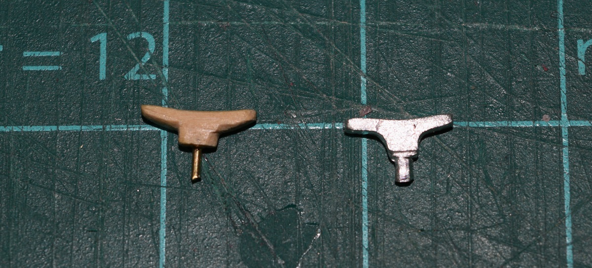 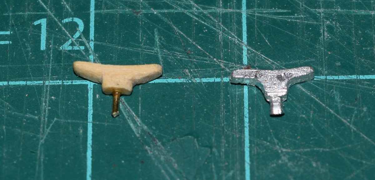 These things are pretty small, those squares on the cutting mat are 1/2". I hold them with jewelers needle nose pliers and use a small file to shape them. I then use a #72 drill in the mill to drill the tiny hole, and I'm using the small brass nails that I used for nailing the planking on the Carmen for the brass rod. I can get two of these out of each of those little nails, and I have a bunch of them left over. The mill is pretty great for this, since the top to bottom thickness of the cleat is only 2.3mm, so the mill lets me get a very nicely centered hole and not accidentally drill all the way through the cleat when working with such a small piece. A friend made a suggestion that I could glue the rods in first, and then use the rods to hold the cleats to shape them... unfortunately I got that suggestion after I finished all 30 cleats! Lol.. 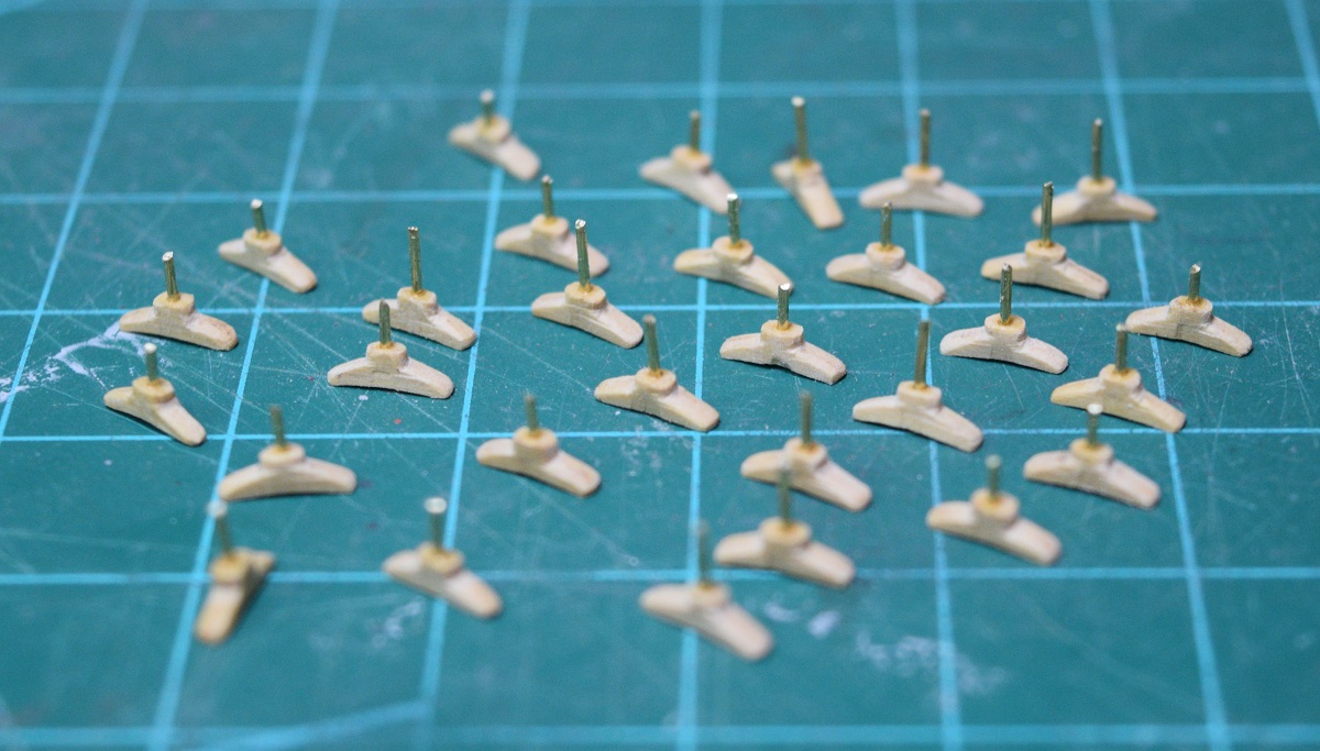 The best part is, that I just spent the better part of a day making cleats that when the ship is done, will almost all be mostly hidden under rope coils. ") I plan to stain these a darker color so they don't stand out as such light wood against the walnut, black, and red. SA Supplemental build log... on the making of cleats. Step 1 is pretty simple, remove the cleat from the laser-cut sheet that they come on and begin cleaning up the laser char. I started by sanding off the char on the flat bottom of the cleats. 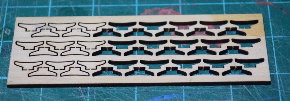 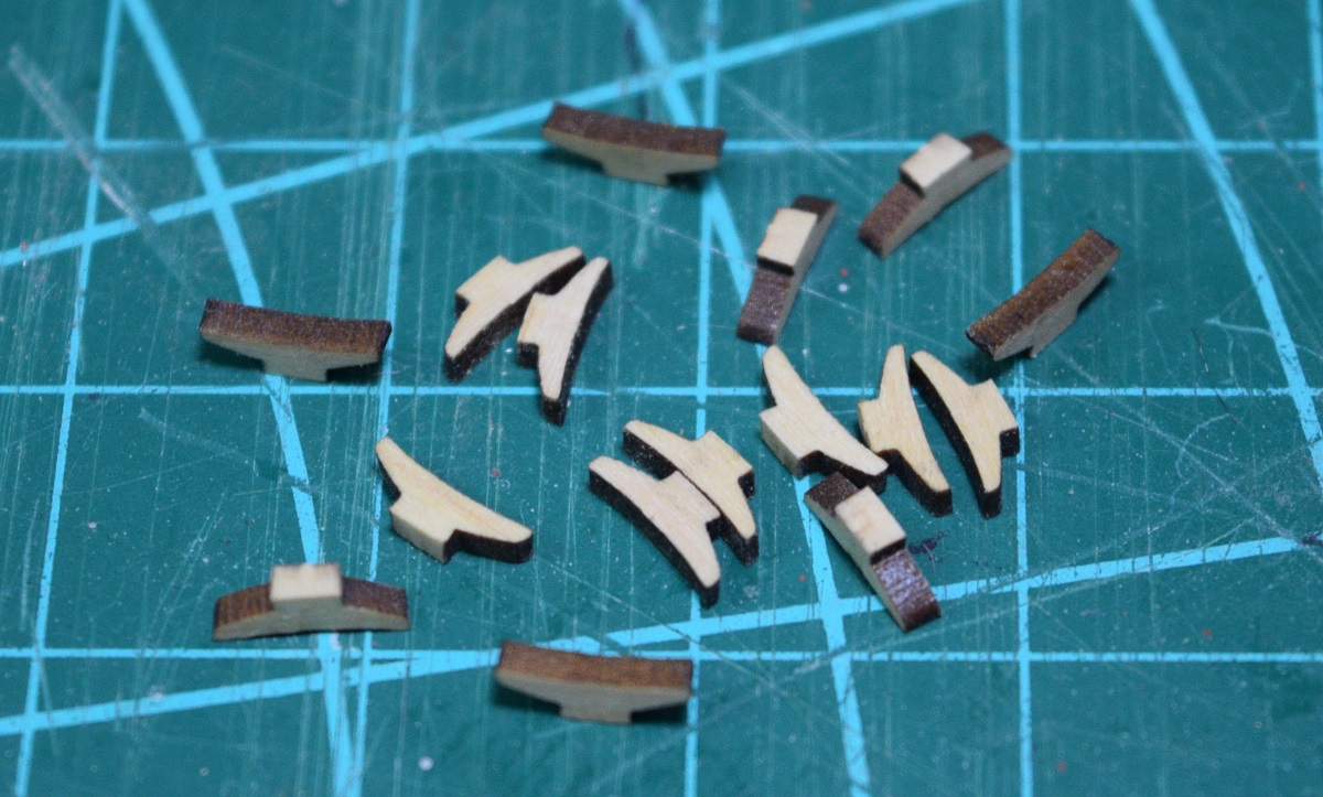 Next I shaped the bottom into the oval shape seen here by using a small file. Side-note - good files in these small sizes are stupidly expensive and generally come from Sweden as jewelers files. The 'hobby' files in these small sizes sold in hobby stores are complete garbage in comparison. One small file like this can run anywhere from $20-$50 depending on the exact shape and cut. 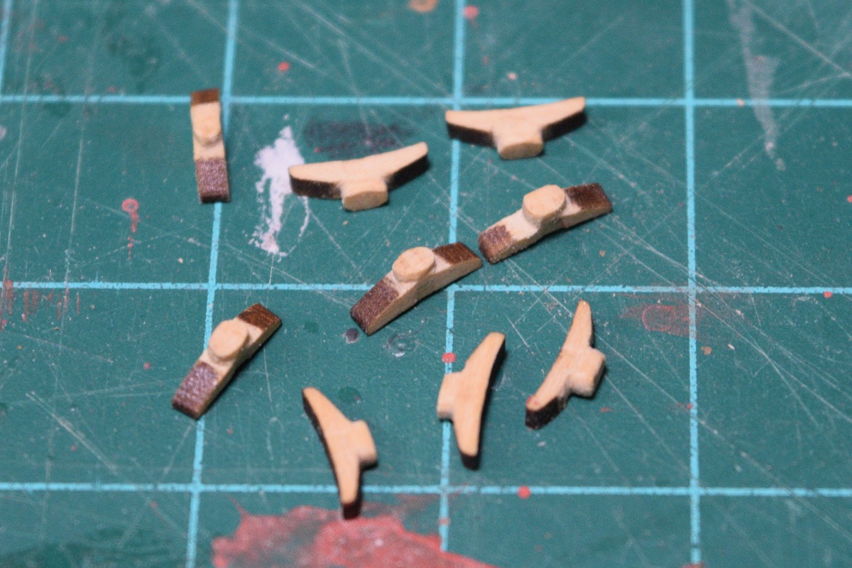 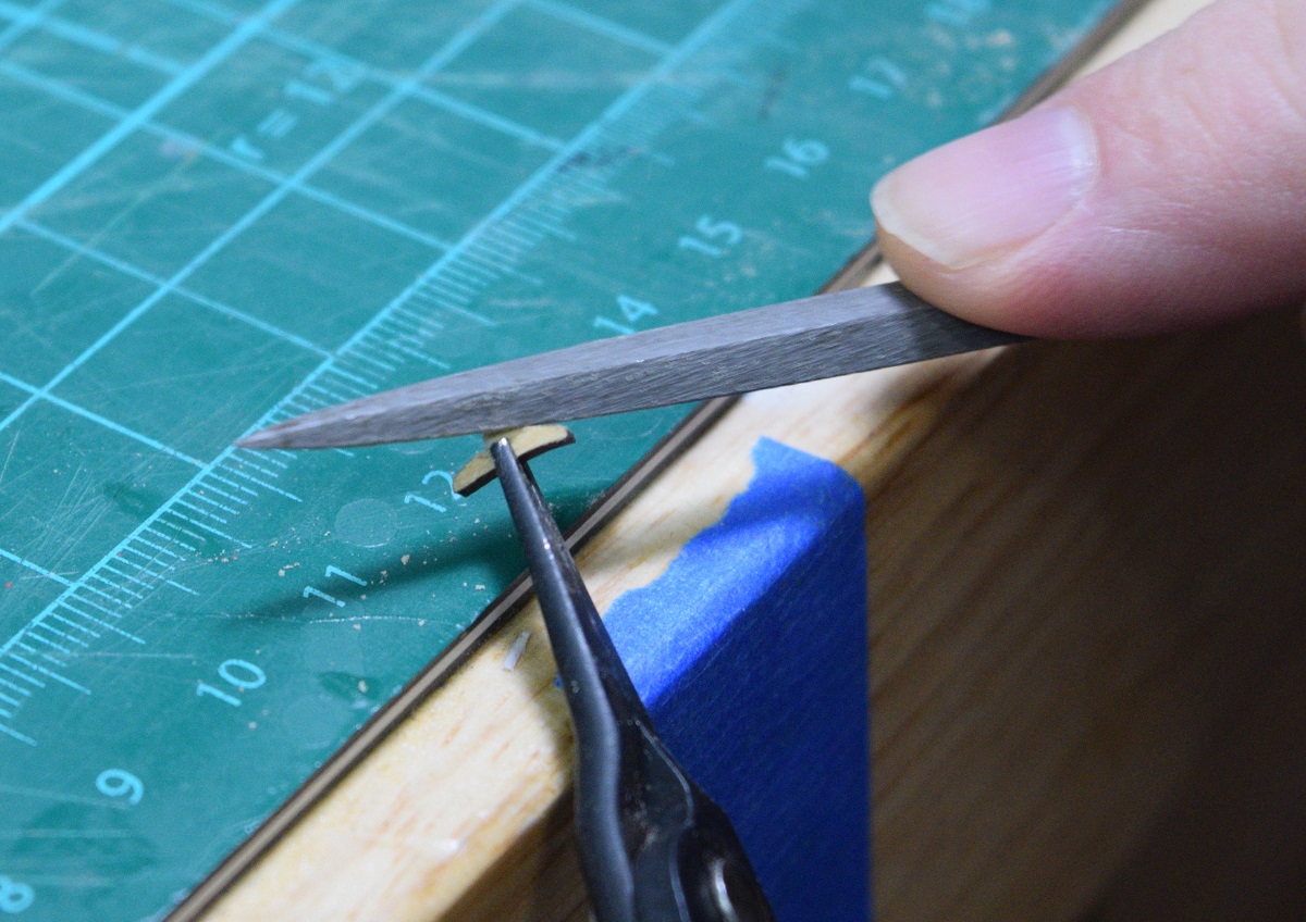 Next I rounded the edges and bottom of the cleat and removed all the laser char form the bottom and ends. 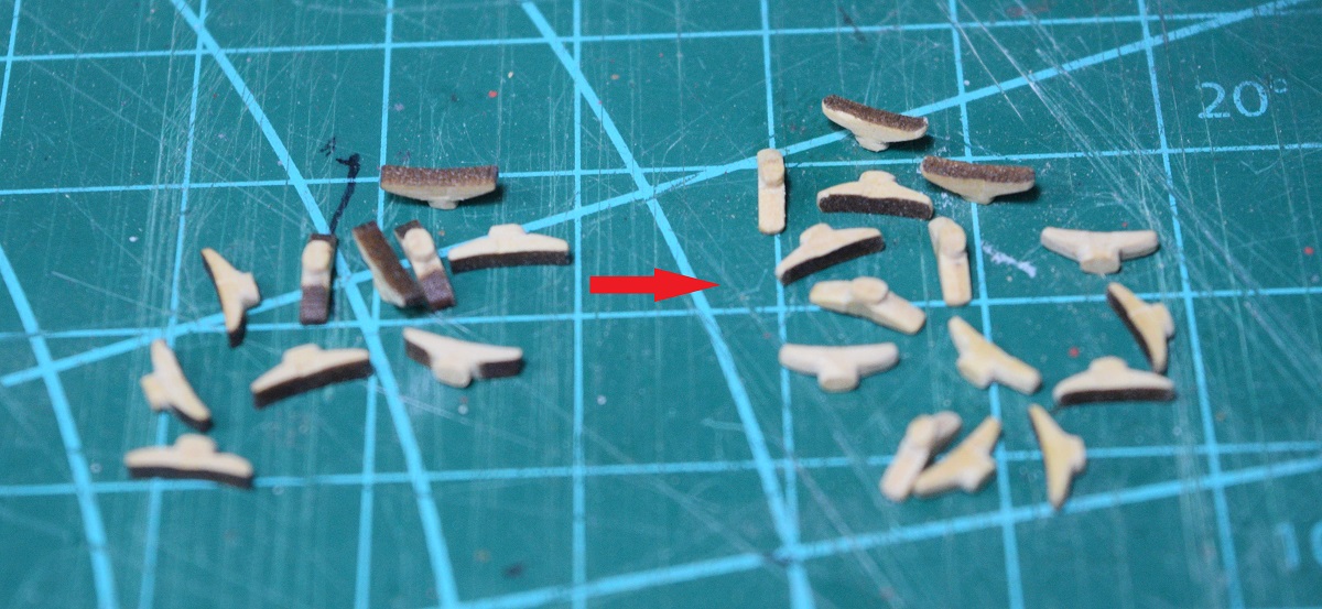 The last of the shaping, and cleaning up of the laser char from the top surface of the cleats. 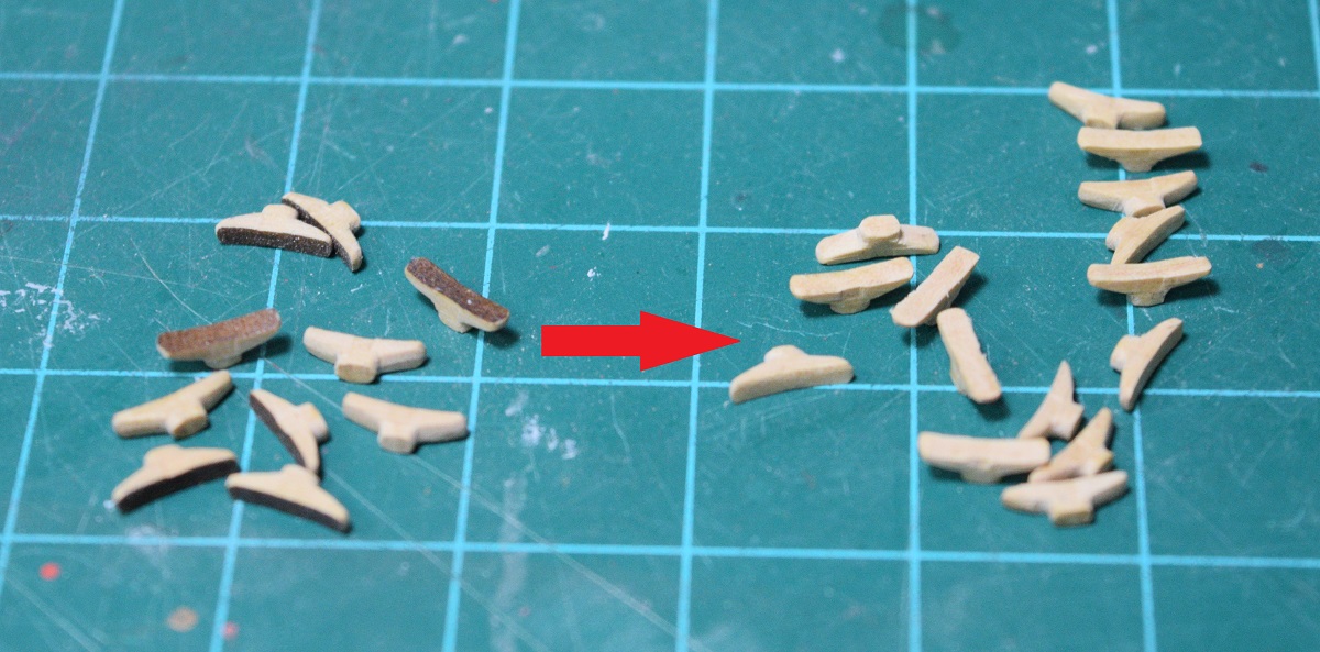 Each cleat goes into the mill and gets the hole drilled for the brass rod that will be used to secure them to the ship. 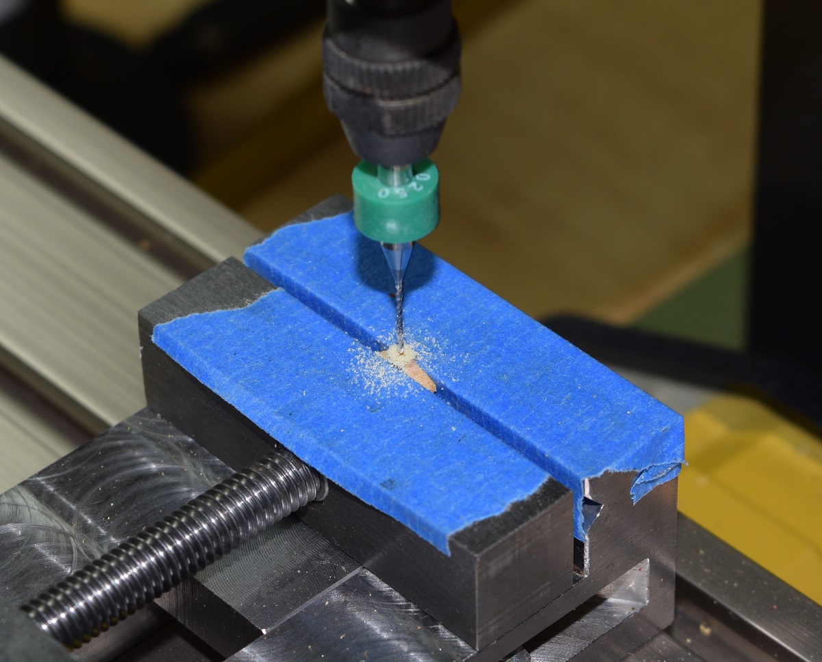 End of side-note on making cleats. ---------------------- I got the holes drilled for the eye-bolts in the cap rail, and trimmed them to size and placed them. They are chemically blackened, and don't show up in the pictures very well at all, so I didn't bother with photo's specific to them. I still have the eye-bolts in the outside the the hull to place, and the ones around the base of the mast. I am going to wait on those until I have the mast made and can test fit it so that I get the bolts placed correctly rather than relying on the plan location. I permanently place the eye-bolt with rings on the deck for the gun haul-in tackle. I stained the cleats with red oak stain, and placed 18 of them on the bulwarks and bow cap-rail. I opened up the bow-sprit opening to fit the bow-sprit, and to do that, I cut down the dowel for the bow-sprit to the proper maximum diameter where it goes through the hull. I cut the hawse holes, but still need to paint them. (Note: Hawse holes are the holes where the anchor line comes in through the bow) 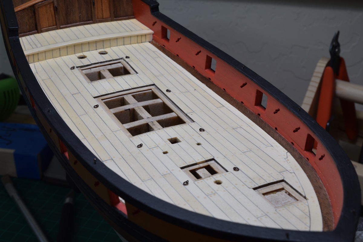 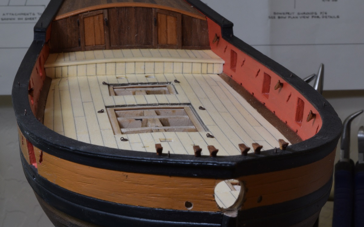 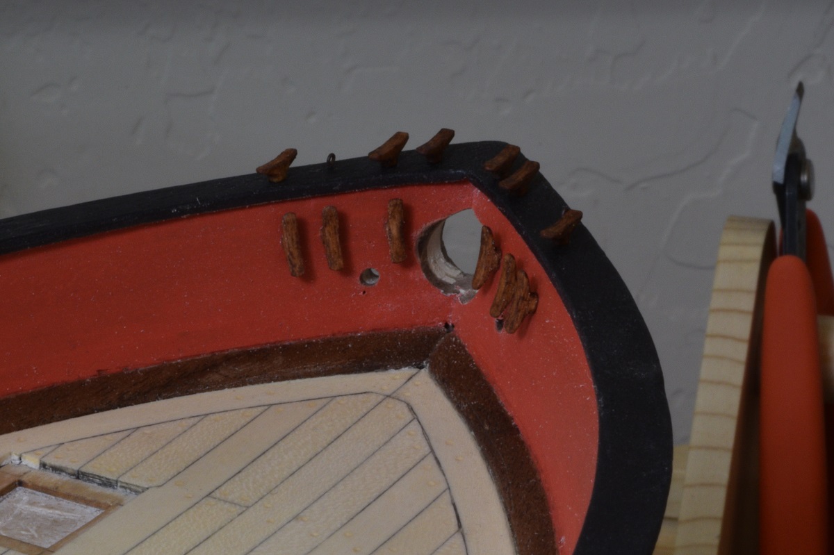 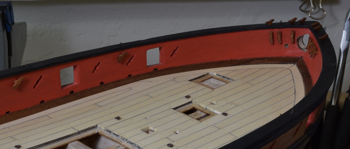 ---------------------- Pretty sure I'm going to like the results of replacing the kit blocks with hooks, blocks, and rope from Syren. If working with these doesn't make me go blind first. Note: Not a single thing in these two pictures except for the eyebolts is from the actual kit. Everything else related to the guns including the ropes later, is aftermarket. 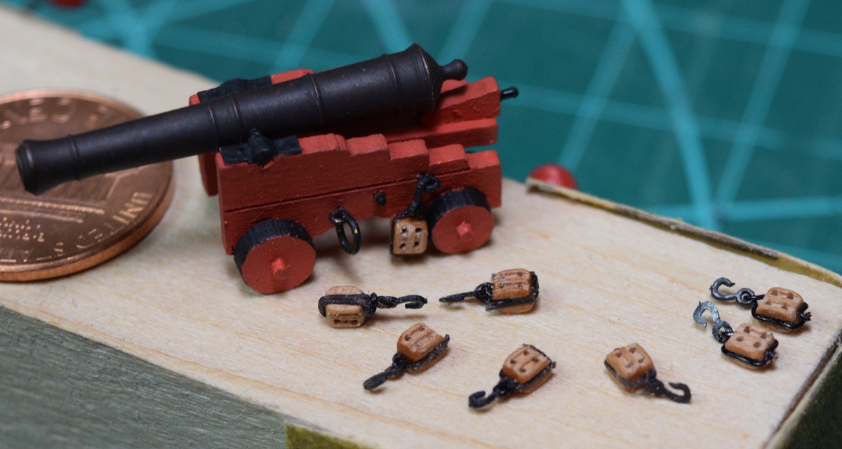 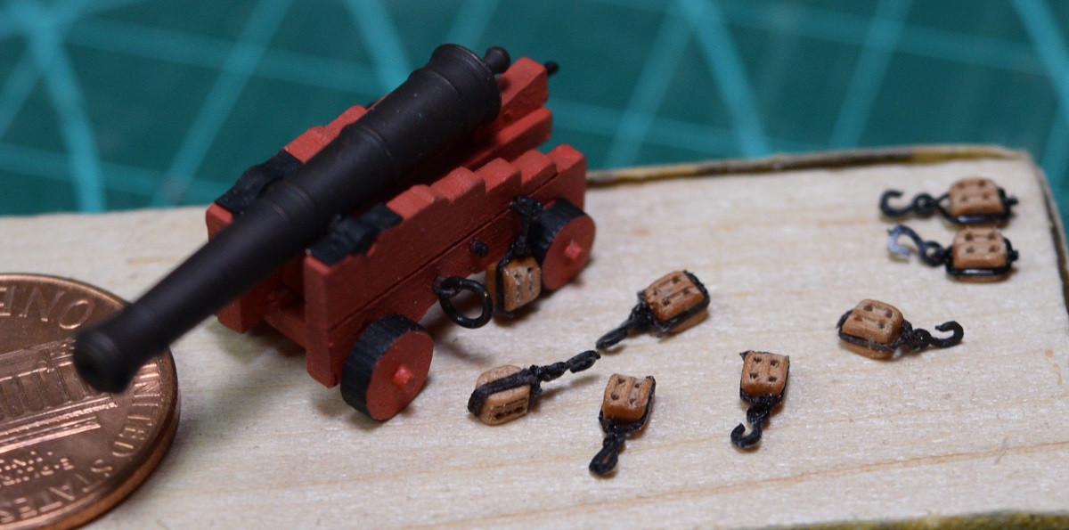 The two on the far right were stropped with 28 gauge wire. The wire was a pain to work with and the block are so small that they are quite easy to crush, so I switched to stropping them with .08" rope. I think they look better, and it lets the hooks 'float' much better as well. Very time consuming though, I'll be working on these for a while, and will probably work on other stuff rather than just sit down and try to finish all the blocks at once. The single blocks are barely more than half this size, so they should prove pretty interesting, since I also have to attach a rope to them! Note: Stropping is the rope or metal that wraps around the block itself which the hook attaches to. The Locator fucked around with this message at 00:56 on Nov 9, 2020 |
|
#
?
Nov 9, 2020 00:52
|
|
|
Moving forward with gun rigging, I made a breaching line and put it on a gun to test fit it.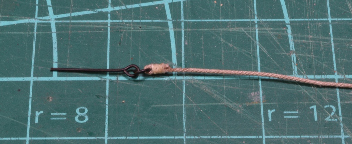 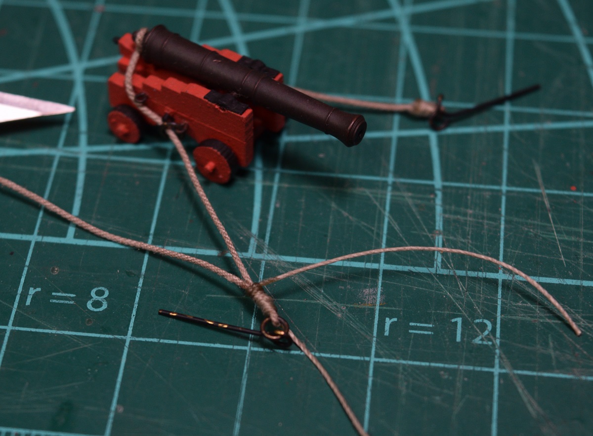 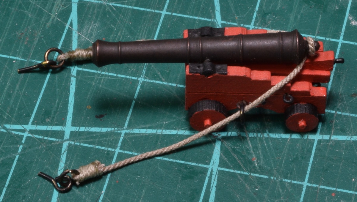 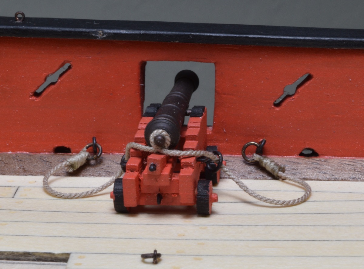 Oops, way too long. Need to pull almost an inch out of this rope I think. I am basing it being too long on the fact that if I pull the gun back until the breaching line actually stops it, I've run the gun back past the in-haul ring-bolt in the deck. I would expect the breaching line to take up tension and stop the gun just after the barrel comes inside the bulwarks, and before the gun starts tearing up deck fixtures. Surprisingly, I got the smaller rope I needed to rig the guns today, so I had to charge forward and rig up a pair of the single blocks so that I could make my first gun tackle. 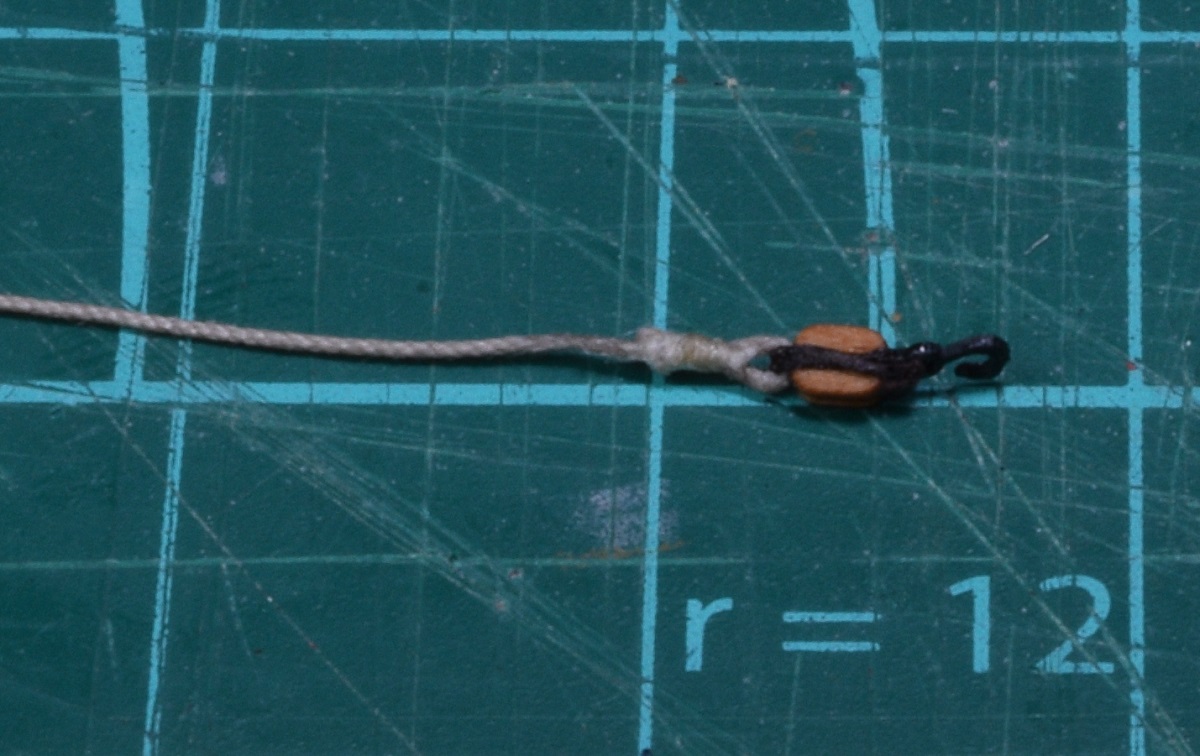 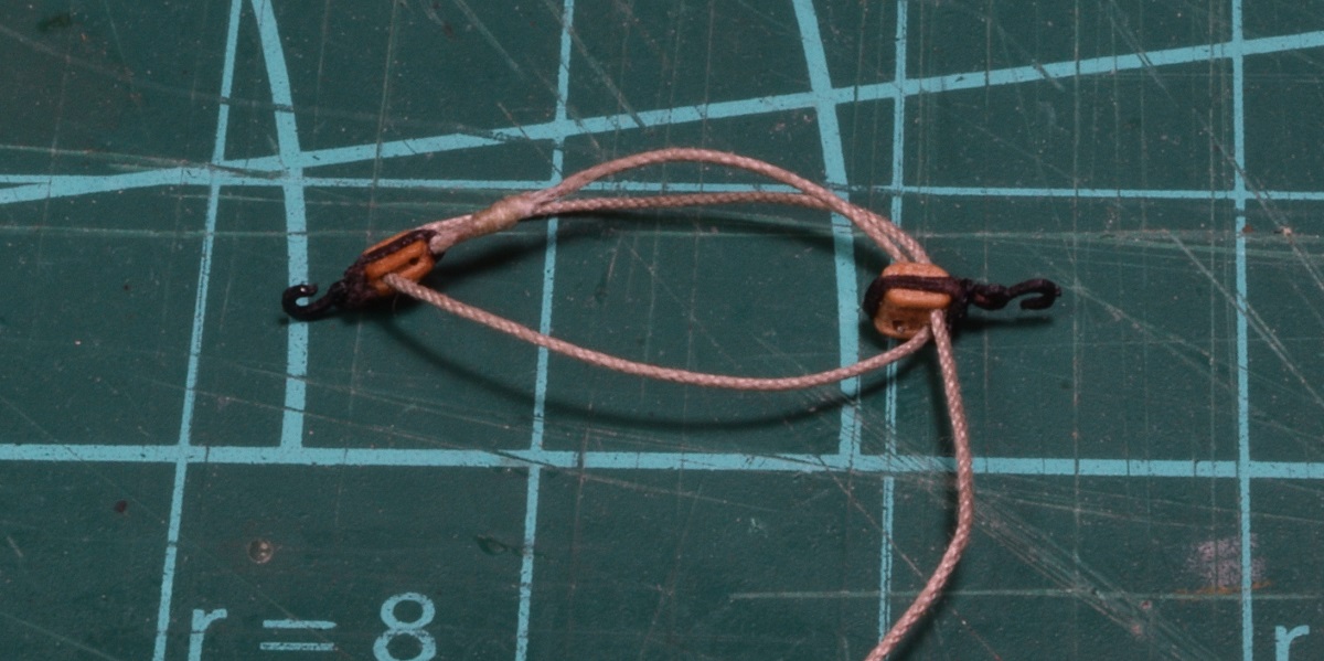 And of course I wanted to see how it would all look, so I plopped it on the deck. 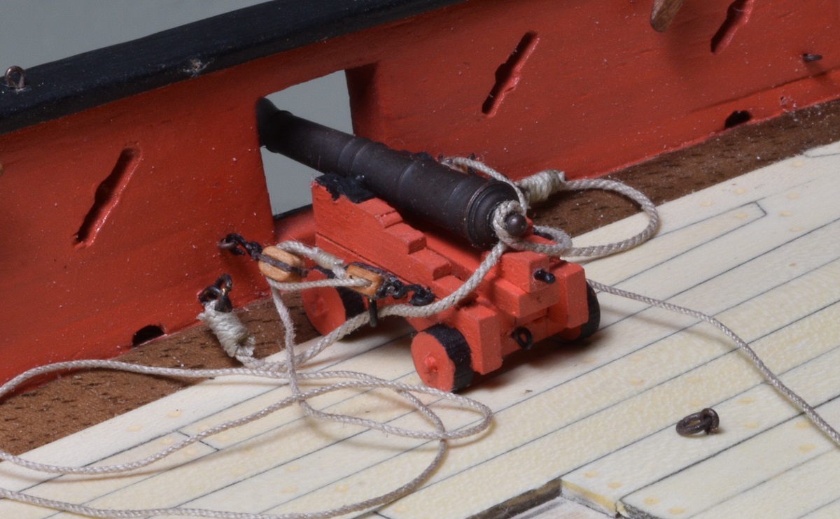 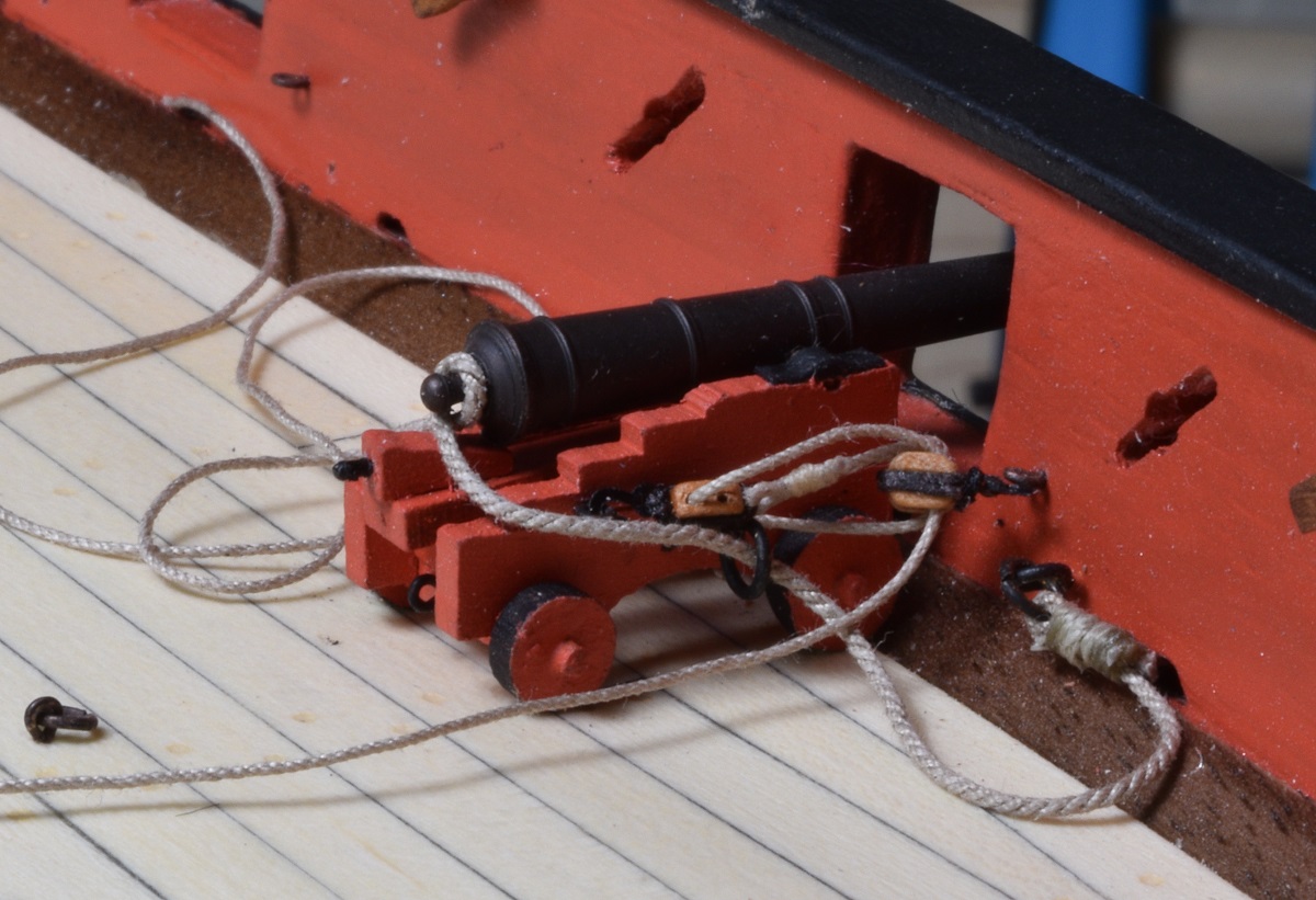 Unfortunately, I got a bit overzealous tightening the tackle on the right side, and while it's sort of hard to make out in that last photo, I broke off the hook that attaches to the bulwark, so I'll have to redo that side again. Also need to be careful of which way I have the hooks pointed when I rig the tackle, as that left side shows, when they are 180 degrees off from one another it doesn't look so great. Not a big deal I can just pull the rope out and re-rig it. ------------------------- Took a break from tiny little blocks tonight, and gave the captain a way to steer his ship. Seems like a reasonable thing to do, given that she has a rudder and all. I did not replace the cast wheel with anything aftermarket, as all of the wood wheels I've seen are really 'fat', and I don't think they look right. I have read several articles on scratch making wheels, but I don't have the right equipment to use any of those methods yet, so I just painted the kit one and used it. Not sure the color is right, but I don't have a lot of brown paints, so this is what I ended up with. 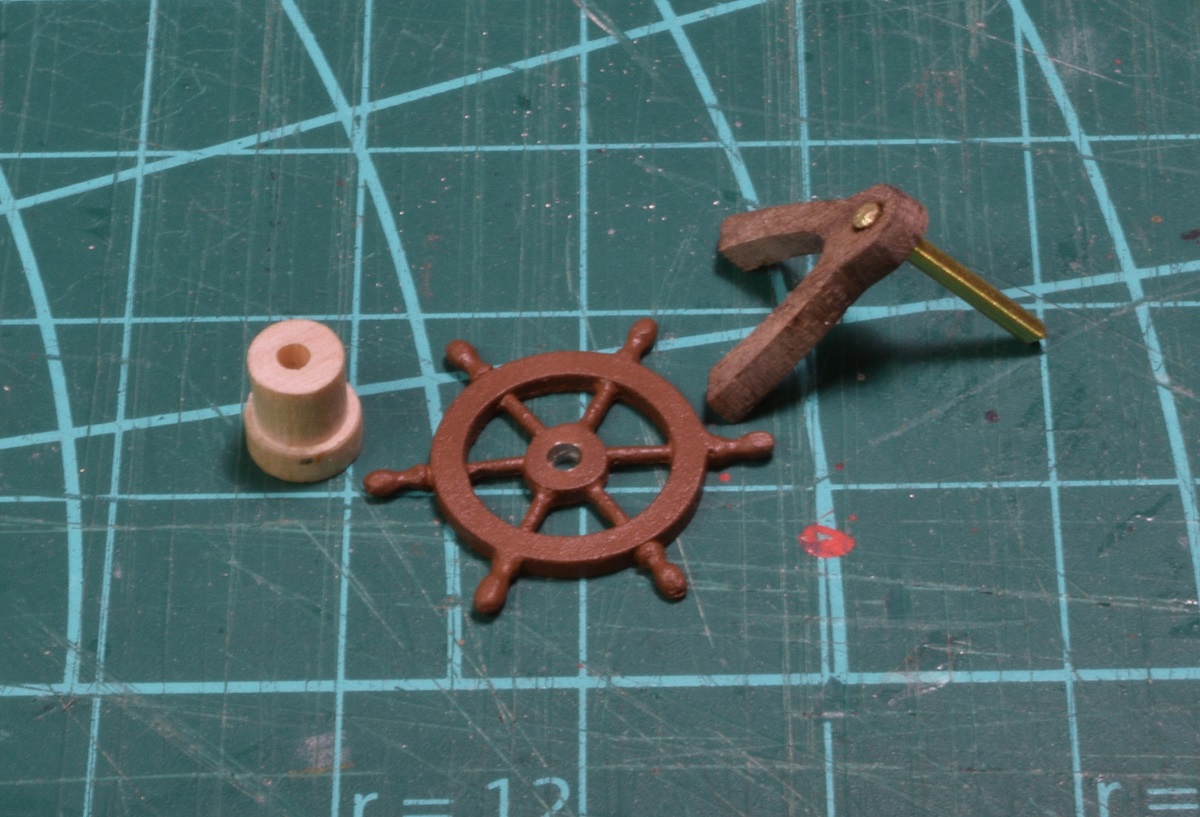 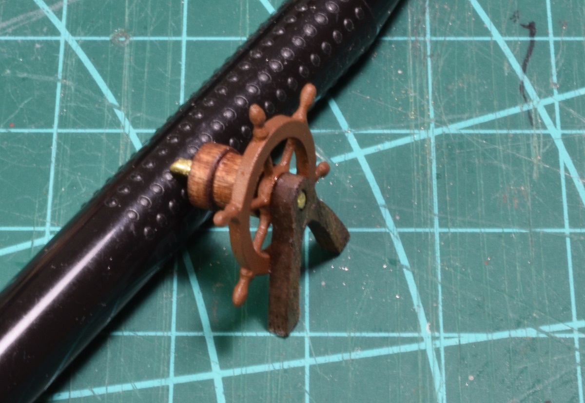 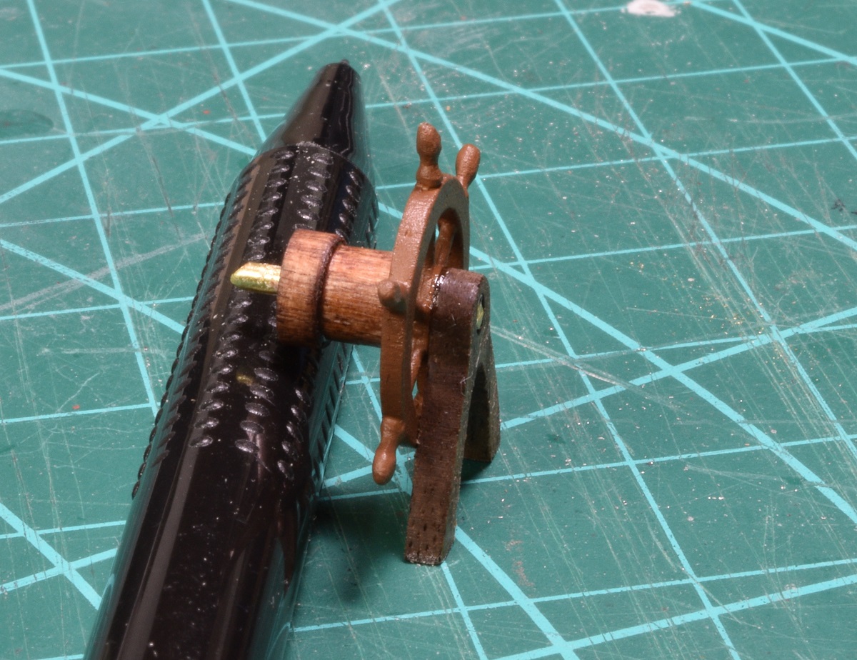  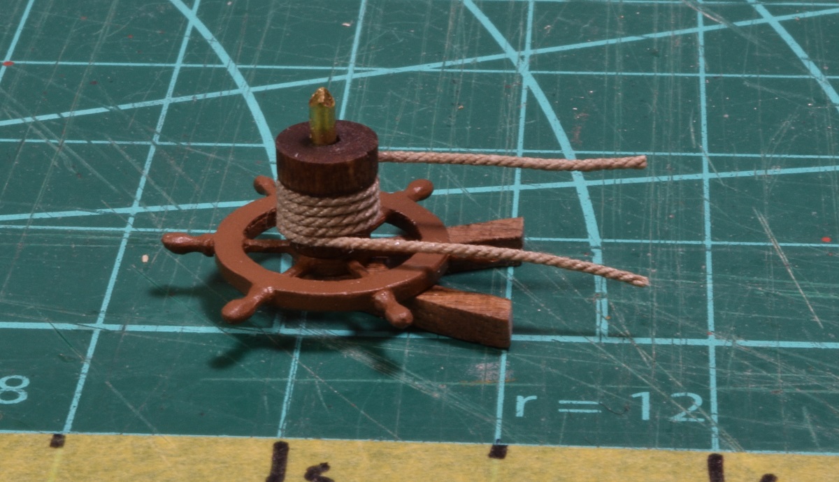 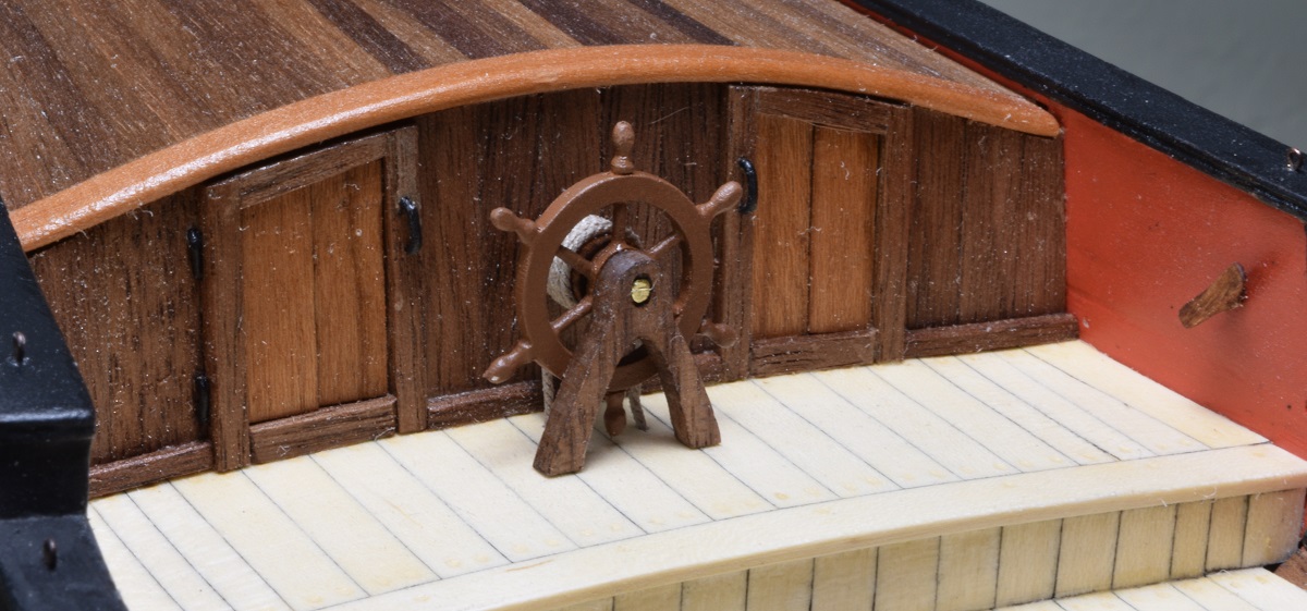 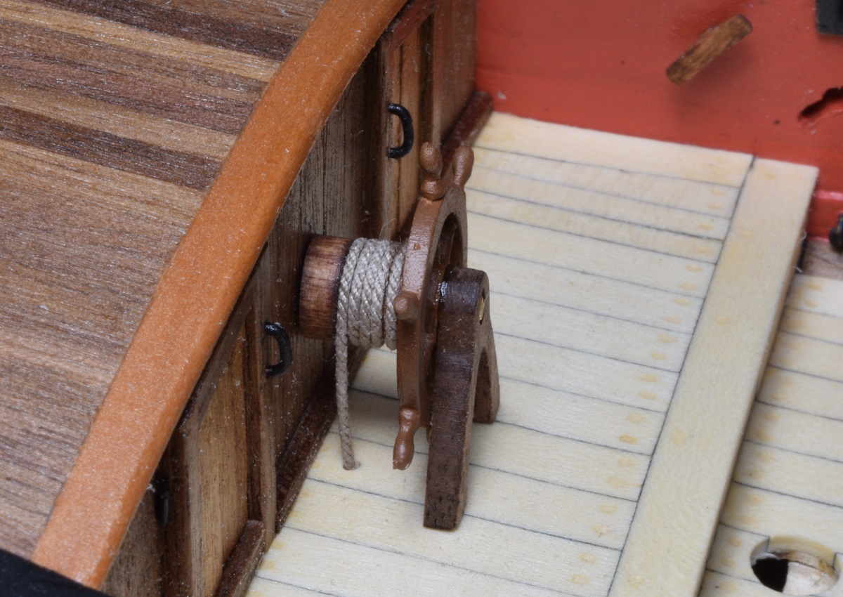 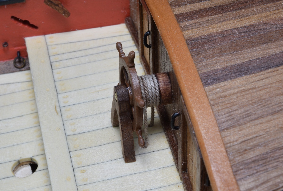 --------------------- I got a new toy yesterday, so today instead of working on getting the guns rigged so that I can actually make some forward progress, I made a side-trip to shaping the bowsprit. Well, when I was done I decided that it was terrible, because the grain in this 'beech' dowel was just huge and terribly obvious. So I made a jaunt down to Lowe's after determining that I didn't have any wood on hand that would work as a replacement, and I purchased some poplar dowels and square stock both. When I got them home and really took a good look at them in the sunlight, I decided that the best piece with the best color and lightest grain was one of the square stock. I cut a length off a little long, and chucked it up in the new toy and began turning the square wood into round wood. 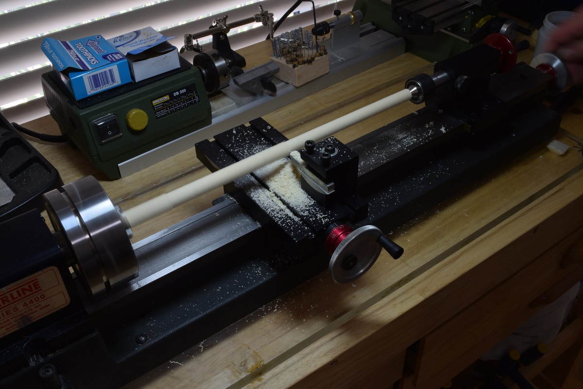 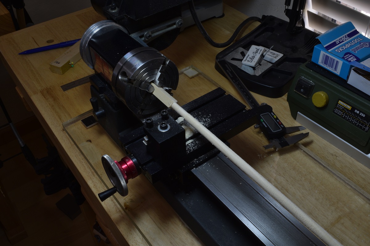 Here you can see how terrible the kit dowel was (grain is huge) compared to the rough shaped replacement I made from poplar. 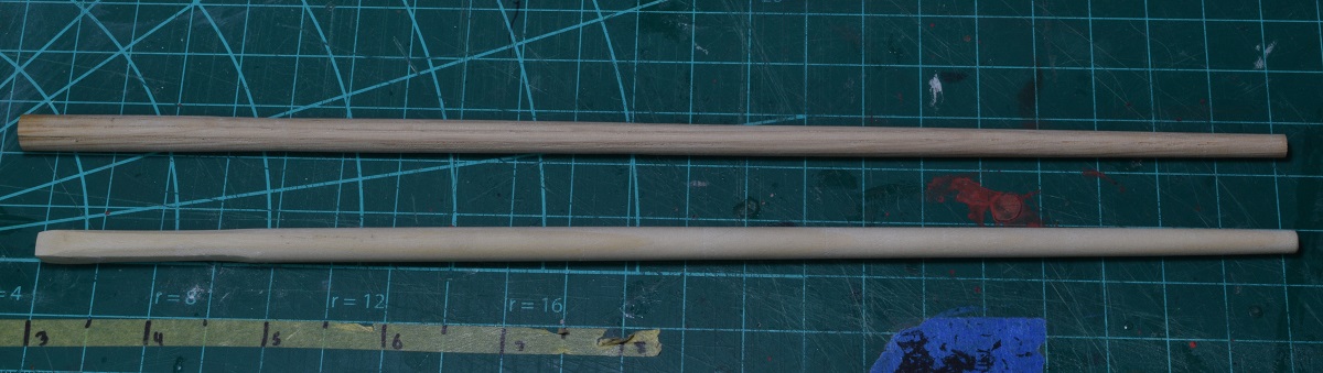 And I stuck it on the boat just to test fit it. 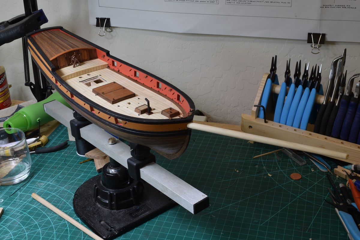 Next, I guess I'll get back to those fiddly little blocks, since there is no point in finishing the bowsprit since I need to get all the deck work done before I mount it. Bit more detail on the new toy. It's a Sherline 17" lathe. I was able to pick it up from a friend who doesn't care for the long bed for what he does and wanted the smaller one, and he picked one up with a bunch of accessories so I was able to get this one with a huge number of accessories also. He threw in a few how-to books and a dvd as well. I then bought a few key items that didn't dome with it like a 4 jaw self-centering chuck. 
The Locator fucked around with this message at 17:47 on Nov 9, 2020 |
|
#
?
Nov 9, 2020 17:45
|
|
|
Just how over-long is the bowsprit in that picture?
|
|
#
?
Nov 9, 2020 19:27
|
|

|
cakesmith handyman posted:Just how over-long is the bowsprit in that picture? It's not over-sized at all and that's only the bowsprit, it gets almost twice that long when the jib-boom is added on! Look at the box photo in the first post of the thread, or Google image search "Bermuda Sloop". Even better is that the boom for the mainsail also extends out over the stern of the ship a non-insignificant amount. This type of ship carried a ridiculous amount of sail for it's size. At the end of this build it will be rigged for 3 fore-sails. A stay-sail, a jib-sail and a flying jib (I think I have the names right).
|
|
#
?
Nov 9, 2020 22:05
|
|
|
Awesome, the finished pictures look a lot more balanced with the sail and mast, it just looks unstable without.
|
|
#
?
Nov 9, 2020 22:42
|
|
|
Yeah, even though I sort of knew how outsized the bowsprit was before I started, it was still kind of jarring when I actually put it in place to see just how crazy long it was. --------------------- Tonight I got back to the cannon. First I made a shorter breaching line and used much smaller seizing thread. I think it came out much nicer. Since I was happy with both the length and the look, I went ahead and fixed the gun into place and secured the breaching line. I then replaced the block with the broken hook, and rigged the out-hauls on both sides and after very carefully pulling the line tight, used a small brush and painted the lines with 50/50 white glue/water mix to help 'fix' the ropes. All that's left now is to do the rope coils, but I'm going to wait until all the guns are in place for that, so I can better picture the space available for both location and size of the coils. 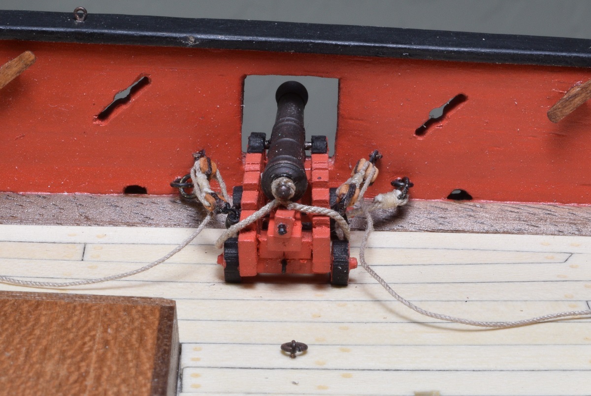 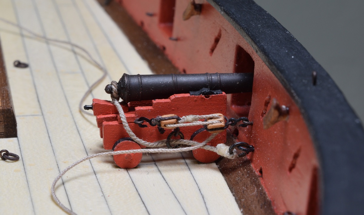 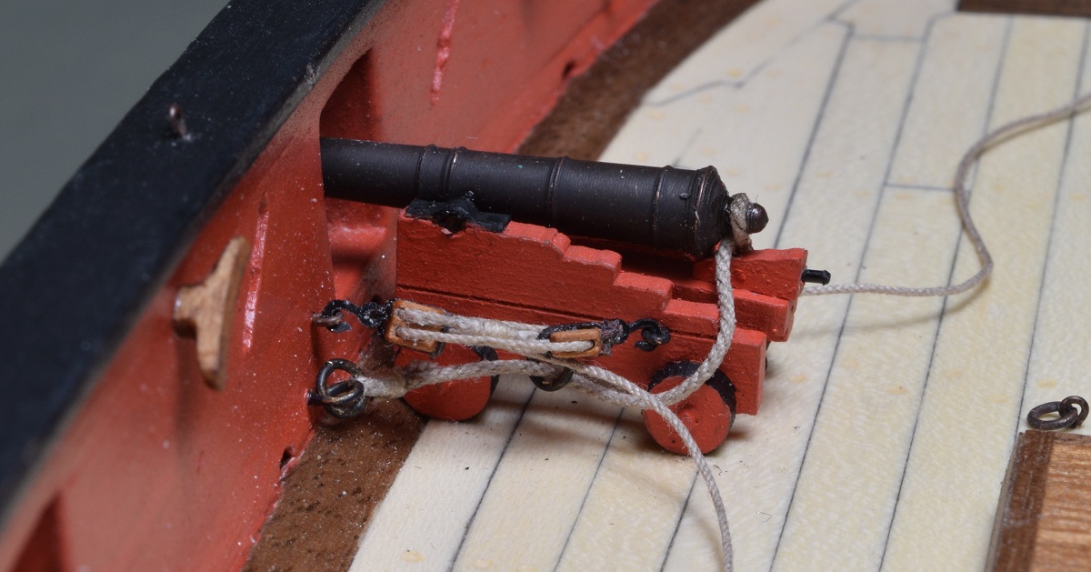 I made 5 more breaching lines, attached them to the cascabel's [SA note: the cascabel is the big round 'knob' on the back of the cannon barrel] on the 5 cannons, and then opened up the side gun carriage rings, put the line through them, and re-closed the rings. 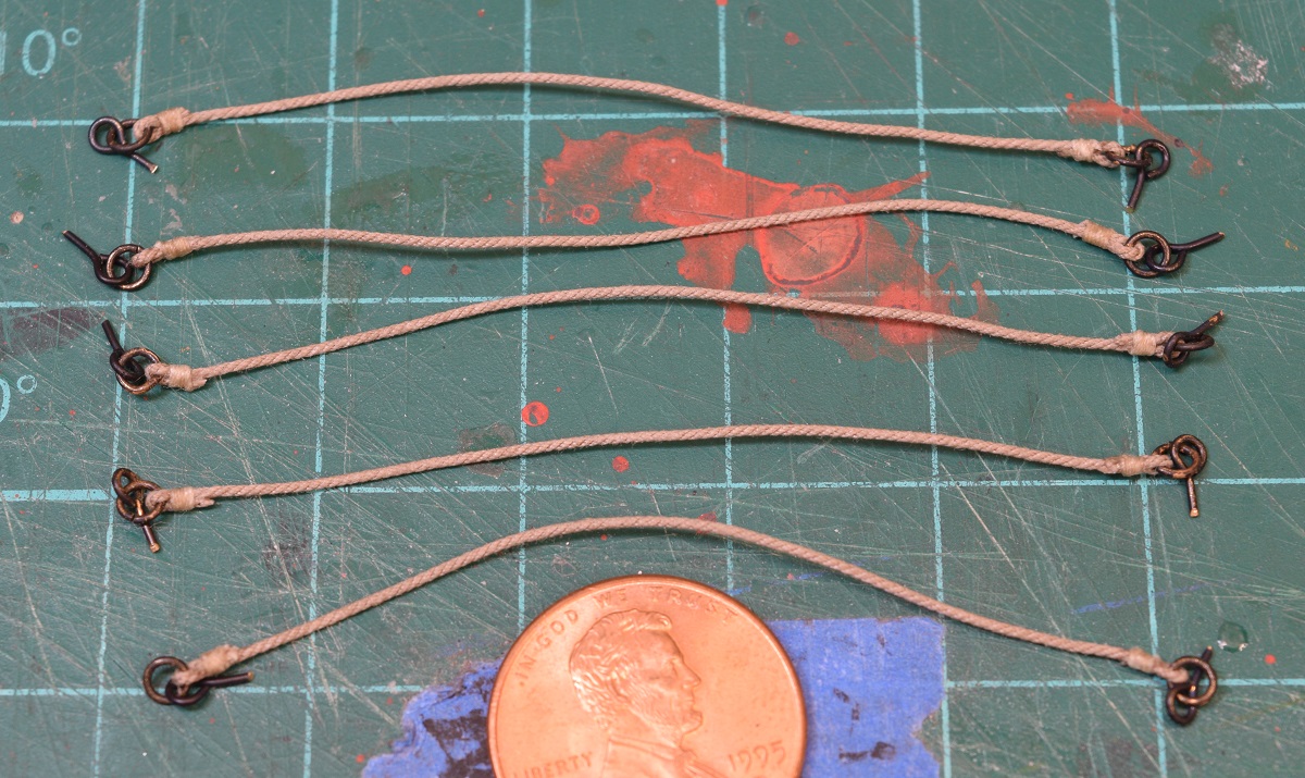 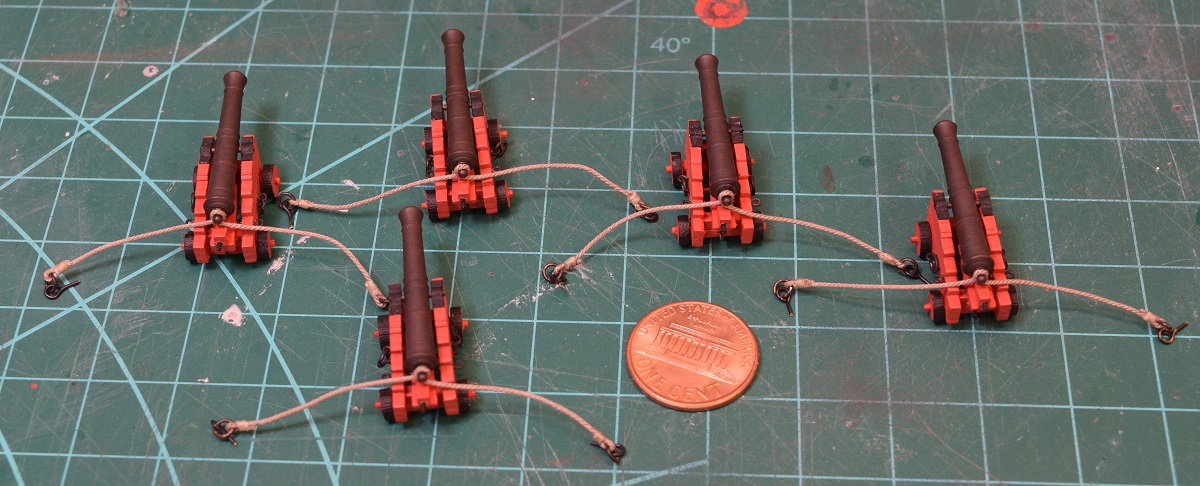 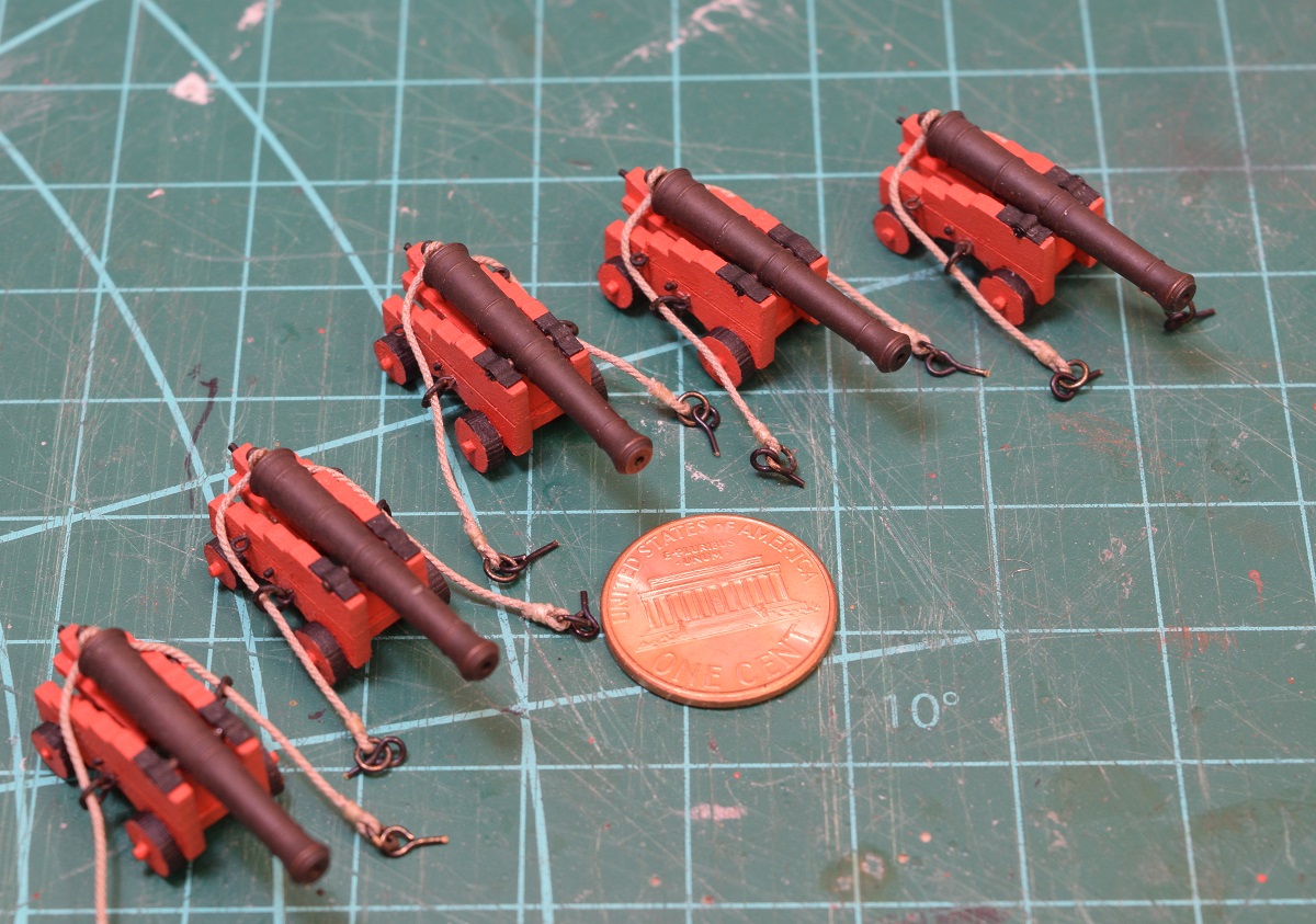 I then attached the breaching lines to the bulwarks, glued them in, and glued the guns down. 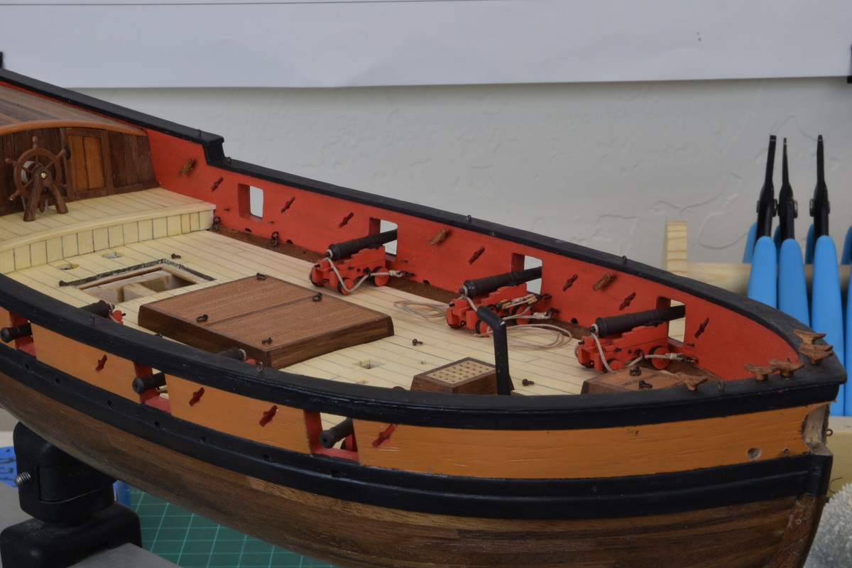 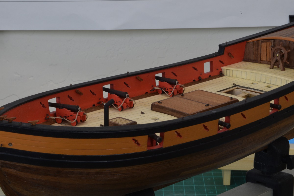 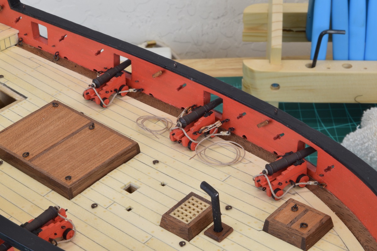 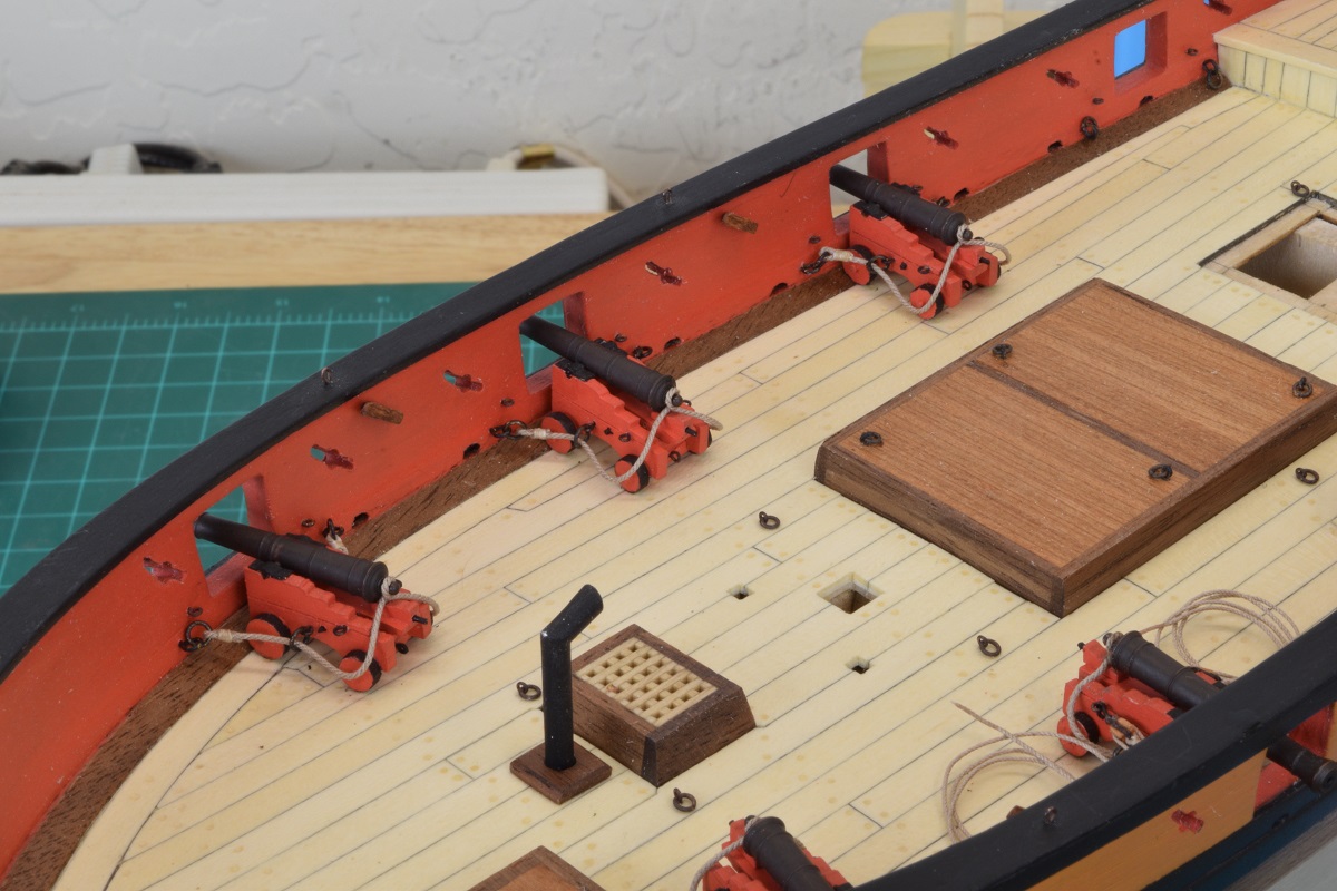 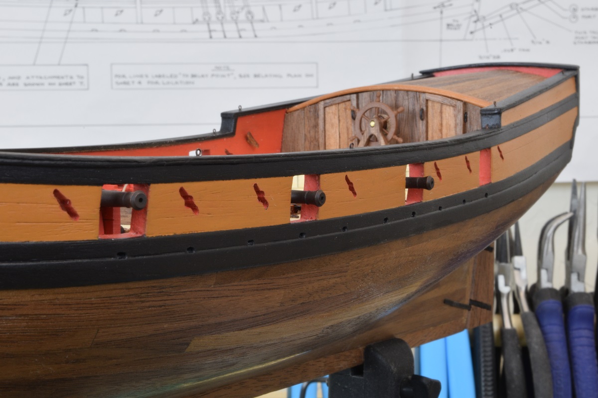 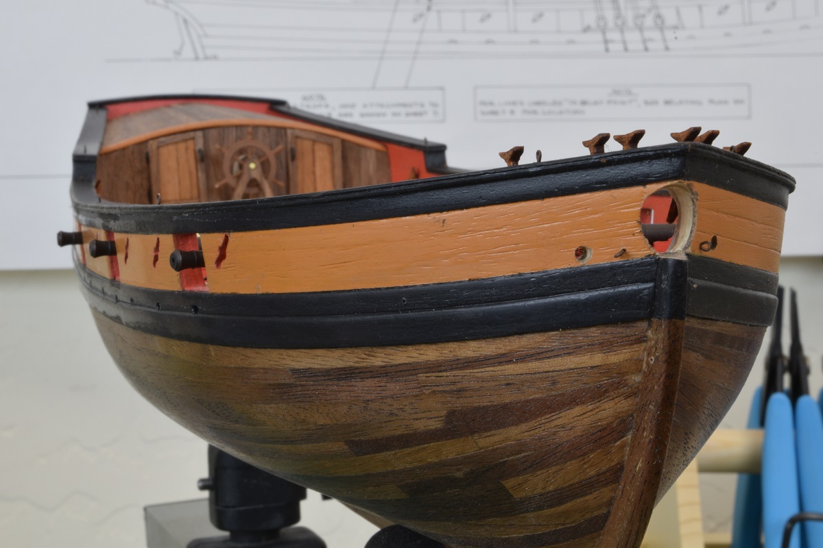 Everything in these pictures is now permanently attached to the ship (except for the sloppy rope coils that are just sitting there). I will attach the companionway later, I need to build and install a couple of elm-tree pumps that go really close to it, so I am waiting on that. I also need to do some touch-up here and there as I managed to ding some things, and knock a cleat loose while putting the cannons on. I really am far too clumsy for this hobby. Based on tonight, I think I'll only be adding 1 or 2 out-haul tackles per night, it's just really tedious working with such small stuff under the magnifier and then fiddling trying to get it all set on the gun on deck. I did 1 out-haul tonight, and also did a single rope coil on the previously completed gun. The method I used was kind of clunky, so I need to go back through some other build logs and remind myself of some of the cool techniques that others have used. I also built the riding bitts, although I didn't glue it down as I think it may be easier to deal with setting the mast later without this right next to that spot on the deck. I've got it so that it's a very tight press fit into the deck, so should be quite easy to place even if I wait until the mast is permanently attached. Picture of the completed (but not glued) riding bitt. I need to do a bit of final filing as it's not quite sitting flush on the deck yet. SA Note: the "Riding bitt" is where a whole bunch of ropes coming down from the mast get secured. 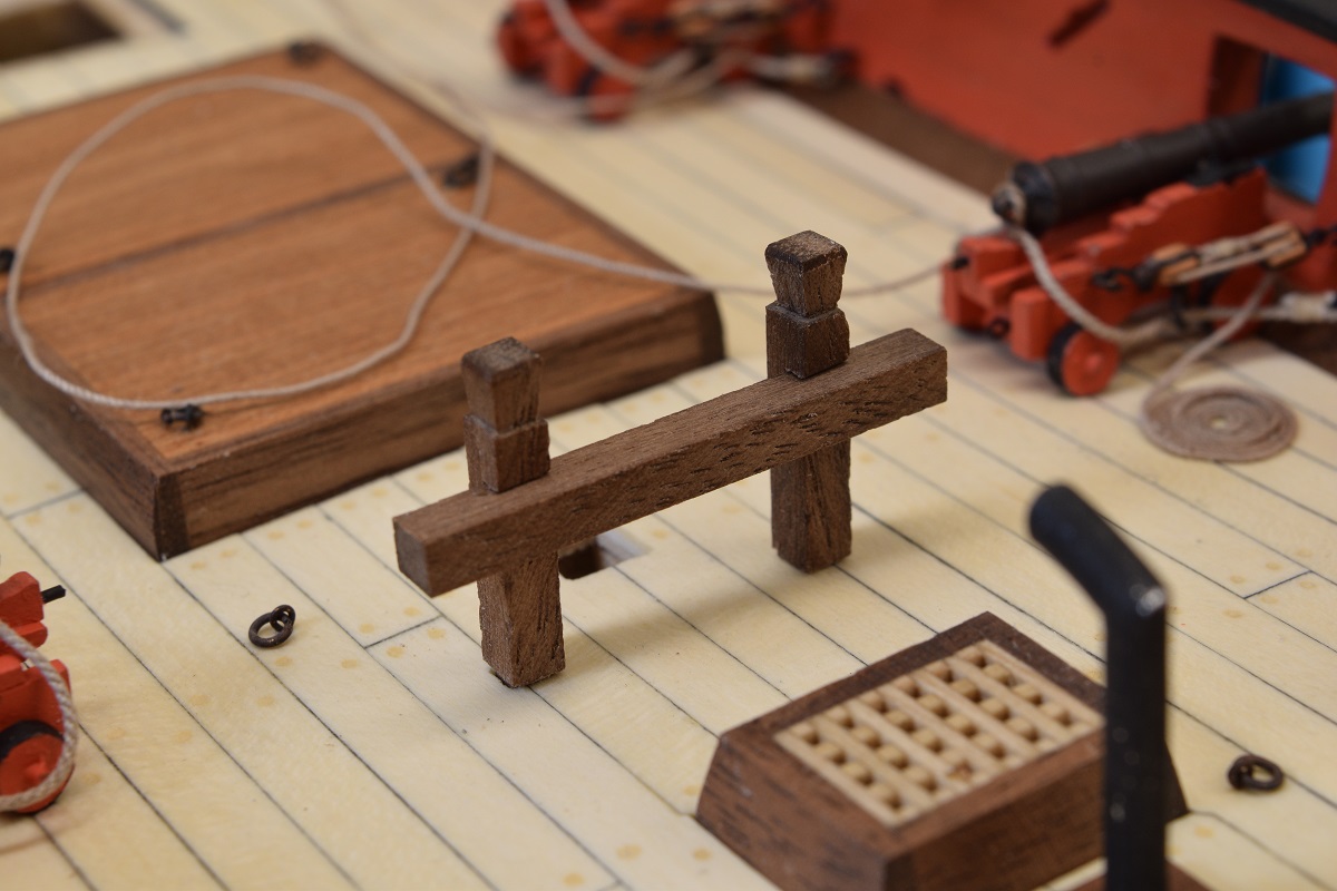 And... I'm half way done with the gun rigging! Well, more than half really since I have the breaching lines done on all of them, but half way done with the out-haul tackle and rope coils. You can almost see what order I did them based on how I got better at them as I progressed. The first two were on the middle gun, where the first coil is sort of ragged, and the other one gets quite a bit better. Then I moved to the rear gun and I found a system that worked better for me and they went pretty smooth (if a bit fiddly) after that. 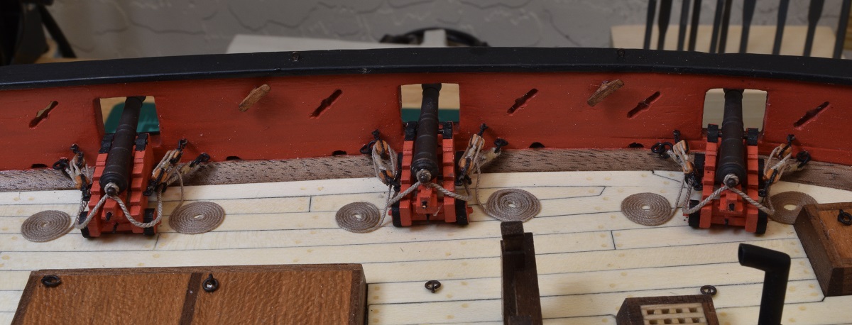 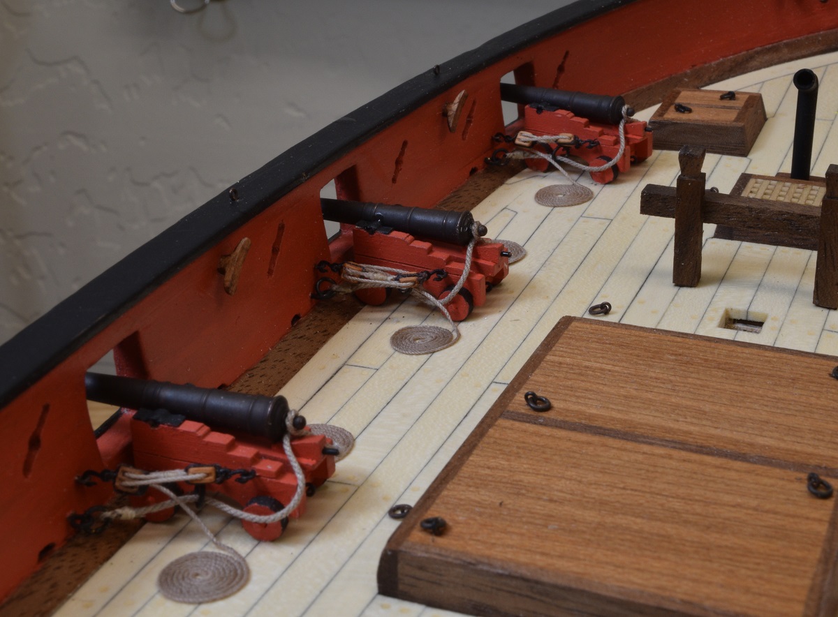 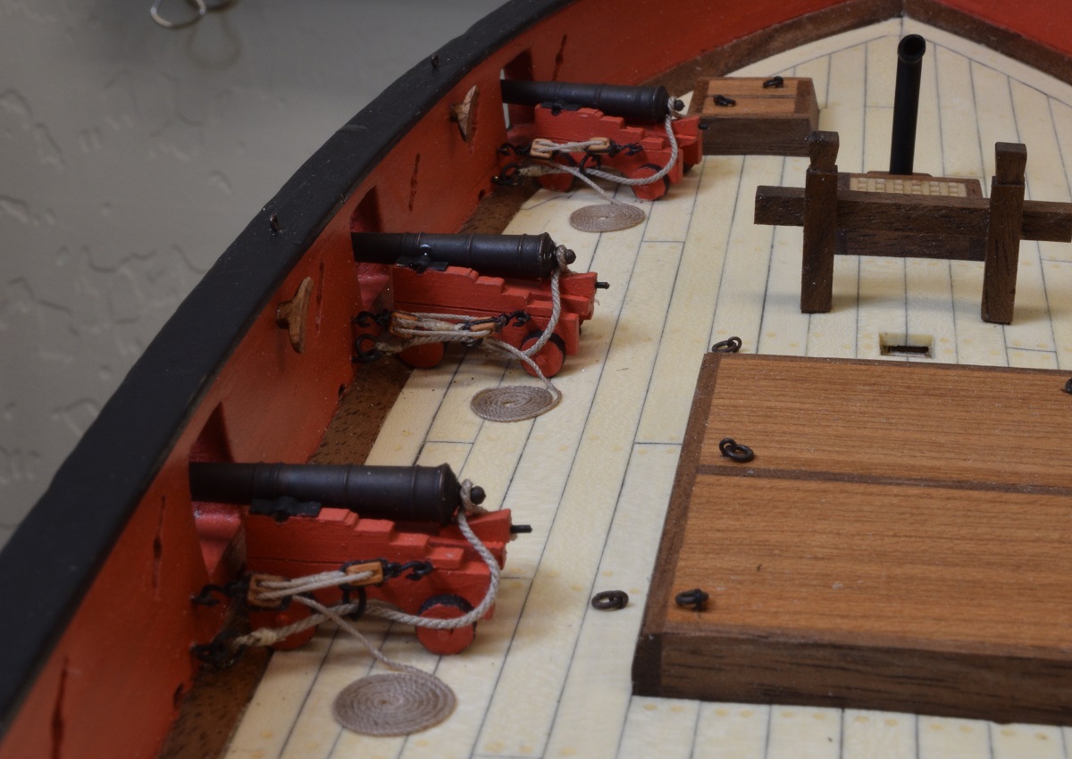 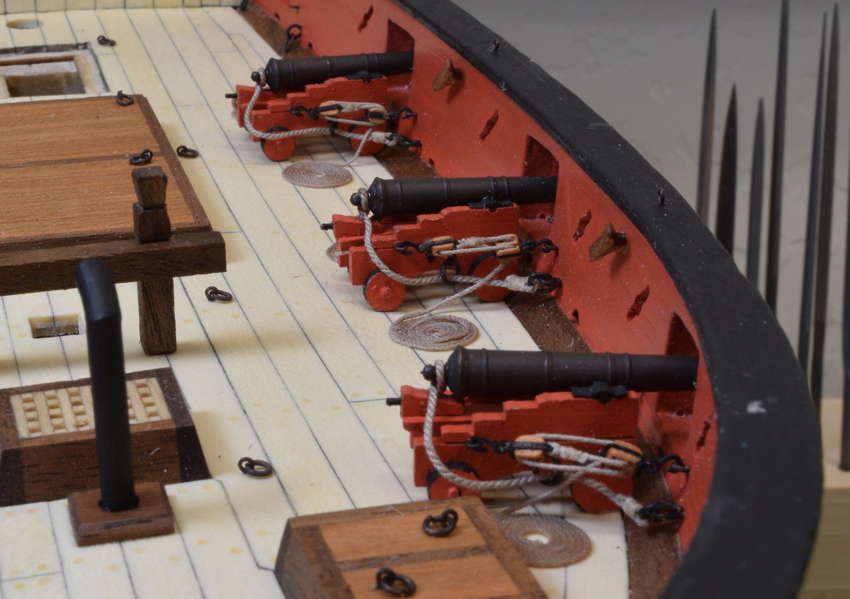
|
|
#
?
Nov 10, 2020 03:10
|
|
|
I had a request (on the original build log) to document my method of stropping the single block to include the tackle rope, so this post is a pictorial step-by-step of how I do that. The materials. I am using Syren 5/32" Pearwood single blocks, Syren 3mm hooks, some generic tan thread I found that is very thin for seizing, .008" Syren brown rope for the stropping, and .012" Syren tan rope for the tackle line. 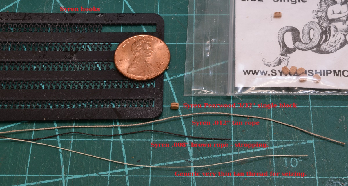 I cut about 8" of .012" line for the tackle rope, this leaves me with about an inch or so left over after creating the rope coils on deck and an extra inch or so for the block end to make it easier to work with while seizing. I cut 6" or so of thread for the seizing to give me plenty to work with. If you leave it too short it can be hard to grab while wrapping the seizing, and it's thread, the spool is something silly like 300 yards long, I'll never run out and if I do it's cheap. For the same reason (ease of working) I cut 5" or so of the brown rope, even though less than an inch is actually used in the strop. 1) I put the single block into a clamp that I secured in my vise, and then tape down the tackle rope to the clamp across the base of the block. Before I tape the rope, I apply a very tiny dab of CA glue to the base of the block where the rope will cross it. I use the tip of a steel X-acto punch tool to apply the glue from a drop on a piece of tape. 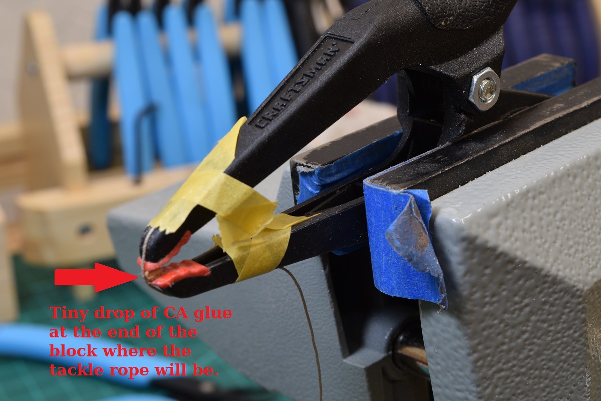 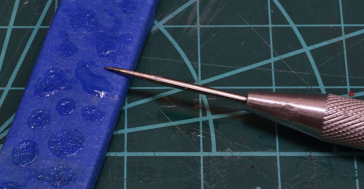 2) I thread the stropping rope through one of the hooks and tie a single knot in the rope *before I cut the hook free from the sprue*!! I lost about half the hooks I tried to thread to the floor when I was trying to hold these tiny hooks and thread them when cutting them free first. Once I have a hook tied to the approximate middle of the brown rope, I soak about 1" or so on either side of the hook in CA glue (from the same drop on the tape I used above). 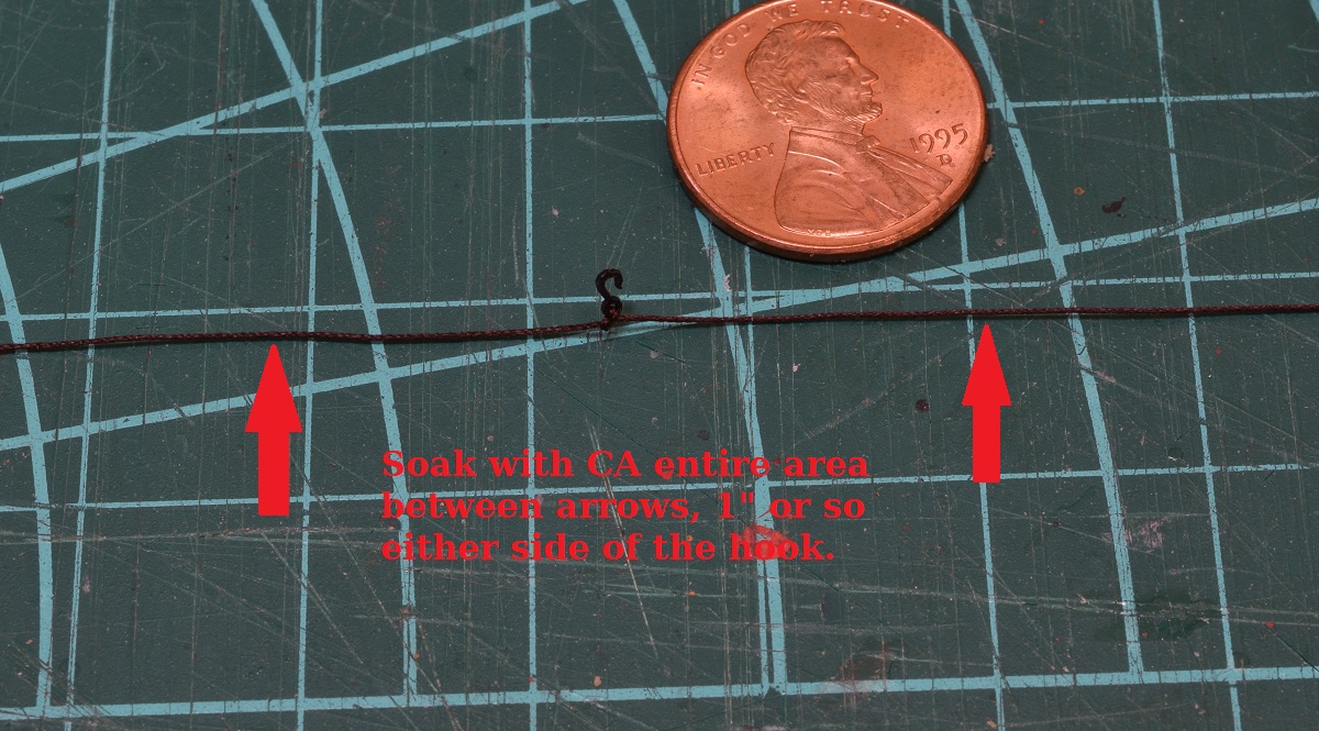 3) I don't really know how to capture a photo 'in progress' of the next step, but I'll try to describe it. Take the hook on the rope and put it in behind the block, centering the hook on the top of the block. Pull the rope down both sides of the block, cross them across the bottom of the block where the tackle rope is, and then continue up the other side of the block and then back across the top where the hook is. This will give you a double rope strop all the way around the block. Continue back down to the base, and then hold them steady for 30 seconds or so to let the CA take a good set. If the ropes are not even on the sides of the blocks, it is easy at this point to use the back edge of an X-Acto blade to push them into place. You can add glue at this point if needed, or in the next step. 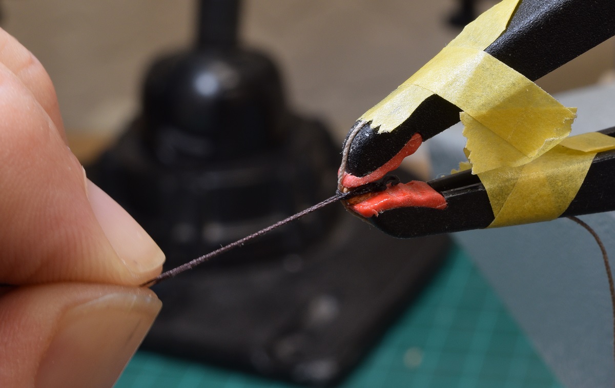 4) Remove the block from the clamp. At this point if everything is looking good, you can trim the rope at the top shoulders of the block. If you need to adjust things, it's pretty easy with either the X-Acto blade or a very small set of pliers or whatever tool works to prod the rope into place. Add another dab of glue if anything comes loose and squeeze it into position with the pliers. 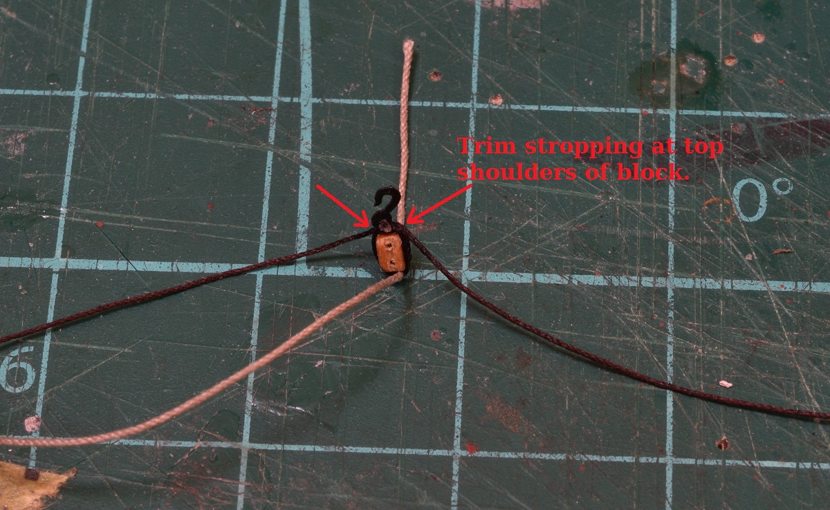 5) Using small flat blade pliers I then squeeze the tackle rope into shape at the base of the block. It will be stiff because of the CA. I also use the pliers to flatten down the ends of the trimmed stropping ropes, adding a tiny dab of CA if needed to get rid of the cut ends. 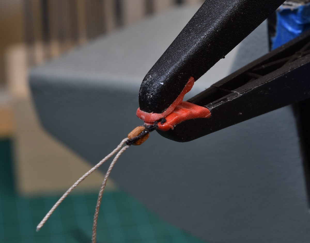 6) Put the stropped block back into the clamp, but this time clamp in the seizing thread with an inch or more going past the block. 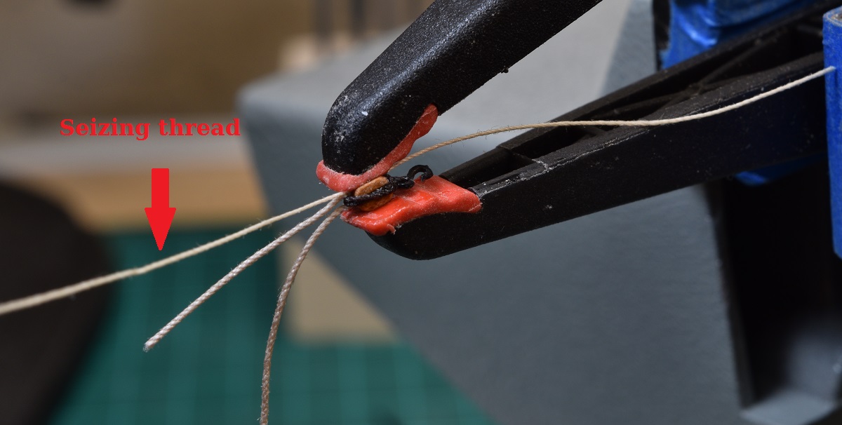 7) To seize the tackle rope, form a loop with the seizing thread, with the top coming back up to the clamp. Leave the loop large enough to be able to thread the other end back through it, which is why I cut this thread longish. Take the top of the thread and while holding everything else in your left hand (or right hand if you are one of 'those' people), and wrap the thread around itself, starting at the block and working away from it. This part takes practice to make it work, as you really can't watch it, as it's all happening between your holding fingers to keep a tight seizing. I use only about 5 wraps on these tiny blocks or the seizing looks way too big. Once you have 5 wraps, take the loose end, and thread it through the loop between your fingers, and pull it firmly until it goes through your fingers so that it's tight. Bent nose tweezers can be helpful for this. 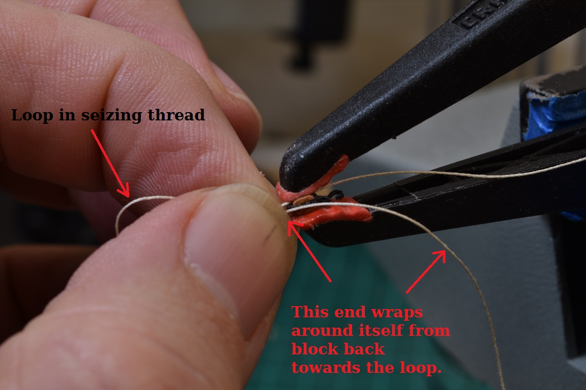 8) Now remove the assembly from the clamp, but keep holding everything with your left hand. Using your other hand, grab the end of the thread that was clamped with the block, and start pulling it. This will pull the loop closed between your fingers. Feel for the loop to close up against the seizing, and then pull the back of the thread tight again. Now you can stop holding with your left hand, and see how the seizing looks. If needed, slide it up closer to the block now, and play with the bottom thread to tighten up the seizing coils. Then finally, pull the top thread firmly until it completely pulls the loop inside of the seizing. You should end up with something like this (the practice part is important here, it took me doing a bunch of these before they didn't look a total mess). Now apply dabs of CA glue to the three points that will be trimmed - both ends of the seizing, and the extra tail on the tackle rope. Trim them off with nippers or nail clippers or whatever you have that will trim very close. 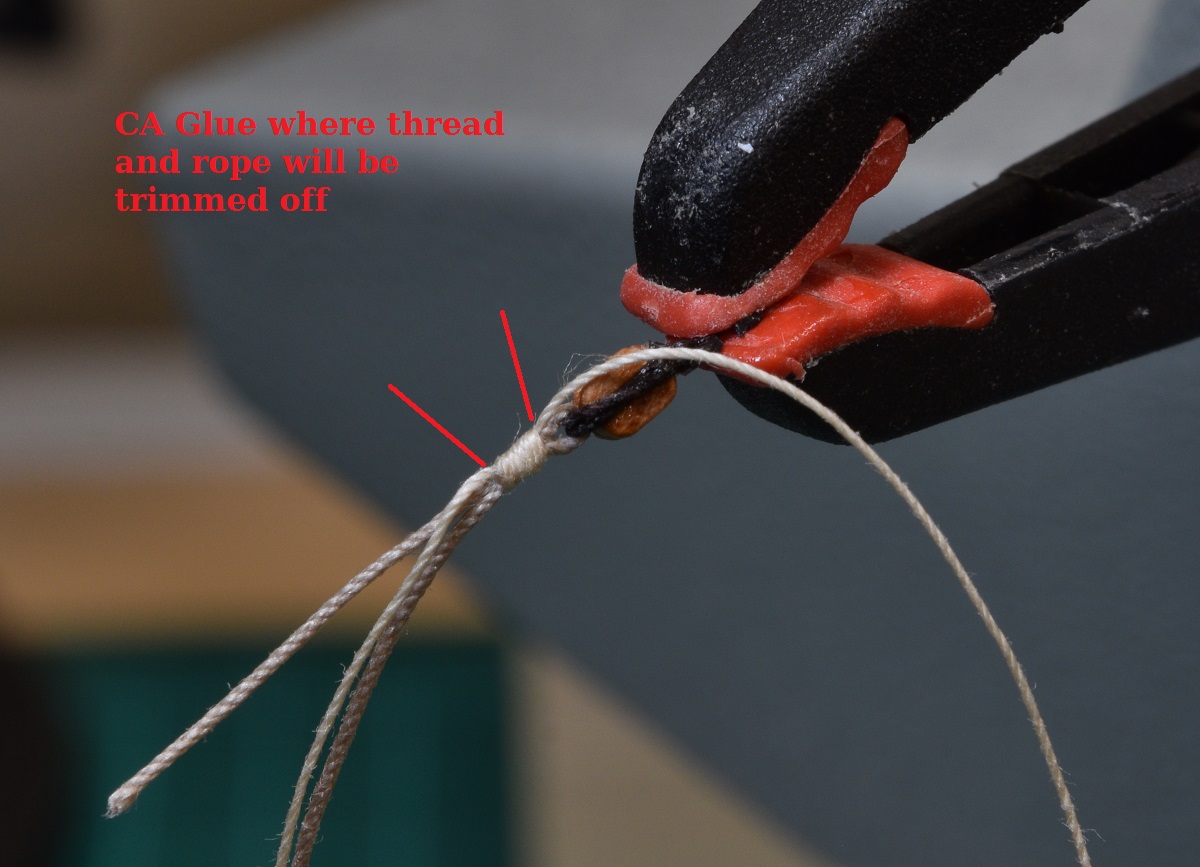 9) Dab a bit of CA on the trimmed ends, and using the flat nose pliers, crimp them to make them blend into the overall seizing. I use a very fine Xuron needle nose plier for this. No substitute for good quality tools I've learned. I get more use out of a single $25 plier than a full set of pliers from Lowe's that are cheap. 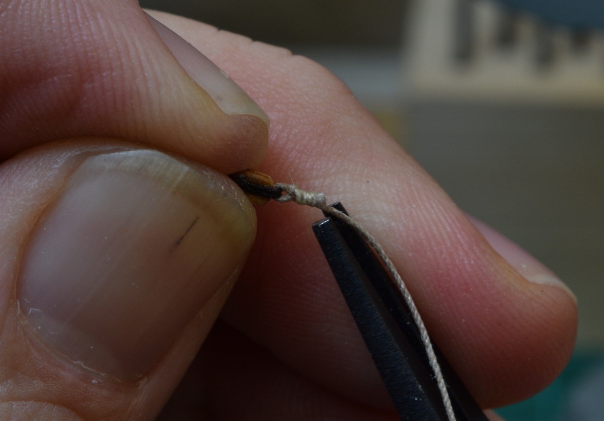 10) It's done! 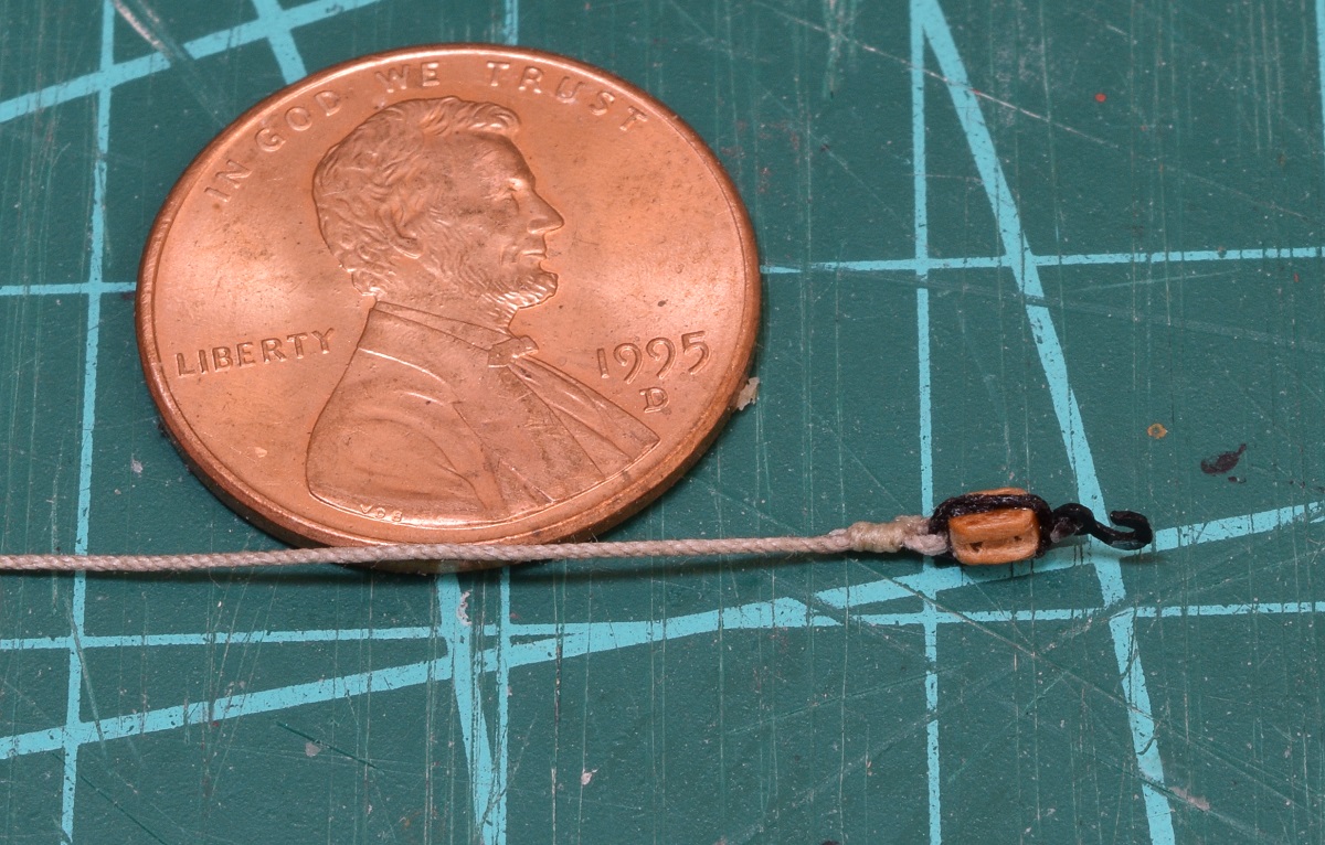 Hope others can find this helpful, it's a system that works well for me, when other systems that I've read and tried just didn't seem to click for me.
|
|
#
?
Nov 10, 2020 06:10
|
|
|
The Locator posted:I had a request (on the original build log) to document my method of stropping the single block to include the tackle rope, so this post is a pictorial step-by-step of how I do that. I was trying to figure out how you made it look like you were siezing the ropes, and it turns out you're just doing a standard siezing on the ropes. Just like you'd do at 100% scale, but TINY.
|
|
#
?
Nov 10, 2020 16:16
|
|


|
babyeatingpsychopath posted:I was trying to figure out how you made it look like you were siezing the ropes, and it turns out you're just doing a standard siezing on the ropes. Just like you'd do at 100% scale, but TINY. Yeah. I tried a couple of different 'fake' seizing methods I had read about, but really just never liked the results. I did use a couple of them (fake seizings) later in the build on some locations where it was just too difficult to do a real seizing. I think I call those out in the log when I do them.
|
|
#
?
Nov 10, 2020 22:16
|
|
|
So instead of finishing the guns on the other side of my ship like I should have today, I totally went off on a tangent, for no real reason other than the idea popped into my head and I felt like it. I apparently have modeling ADD. I played with the Catheads. The base parts are part of the laser cut walnut parts, but the holes for the tackle to go through are not pre-cut of course. The kit instructions are to drill 4 holes, and then using your X-acto blade, cut a shallow slot between the hole pairs in order to make a fake sheave. The slot would be just deep enough for the rope to be flush with the top surface when the rope then runs through the holes. I apparently don't put any value on my time at all, so I decided I was going to make working sheaves with actual little tiny brass pulleys in full slots instead of faking it. First I cut out the slots, and then drilled a hole through the sheave slots for the axle to go. Here you can see the catheads with the other items I used - a brass rod for the axle, and a brass tube to be cut into the pulleys. 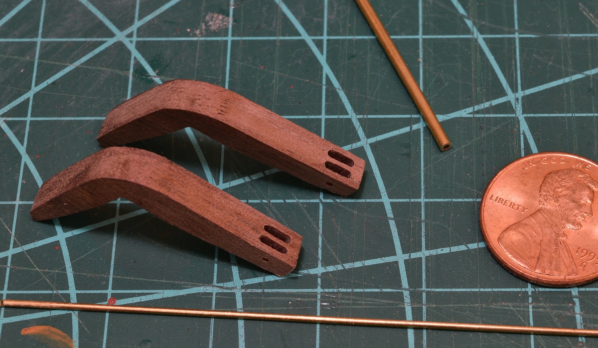 Next up was cutting little tiny slices off of the tube to make the pulleys. 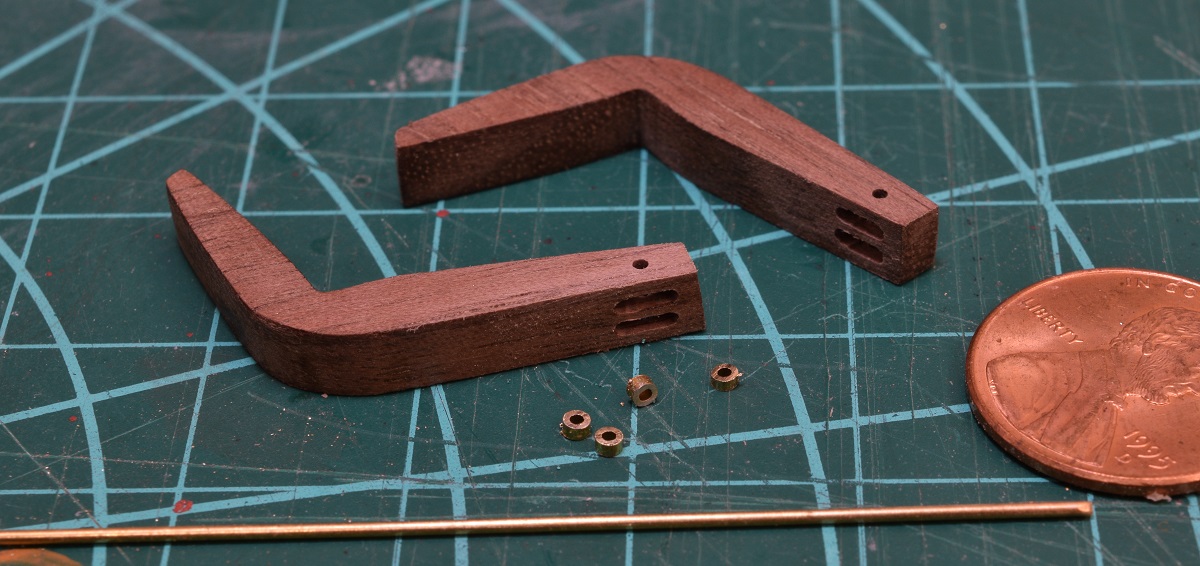 Then sticking the little pulleys into the sheaves and fishing the axle through them. I secured the axle to the outside edge by applying super-glue and working the axles a bit to allow capillary action to pull the glue into the catheads. 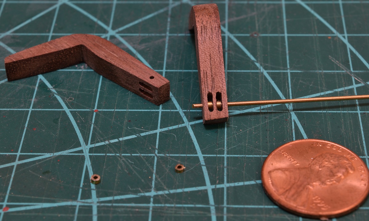 Complete! Then I fished a .021" rope through one of them to test it. Works perfectly. Such a huge waste of time for the heck of it on something that nobody will ever see once it's rigged, but hey, I had fun! 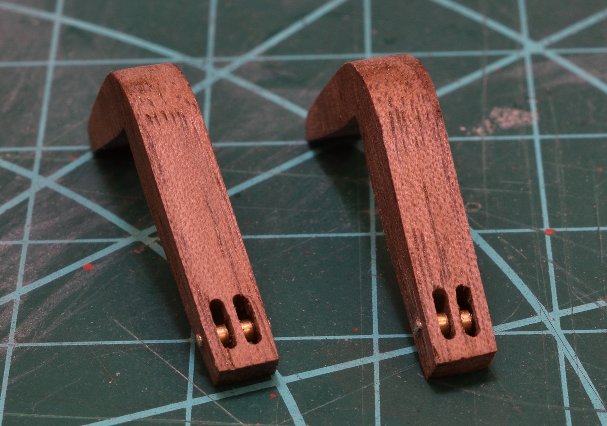 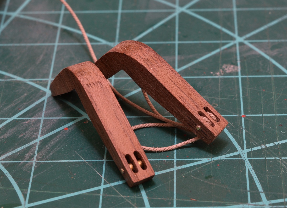
|
|
#
?
Nov 10, 2020 22:19
|
|
|
Oh - definitions. Catheads are the big wooden things that stick out on either side of the bow that contain a pair of 'sheaves'. Rope is strung through these and used to pull the anchor up out of the water to secure it after it's winched up to the surface. Sheaves are just slots that contain pulleys inside of them. They are used a lot on wooden ships it seems. I used the mill to cut the slots.
|
|
#
?
Nov 10, 2020 22:22
|
|
|
That's incredible.
|
|
#
?
Nov 10, 2020 23:35
|
|
|
Went back into the workshop and made the pumps. The kit used to include walnut dowel for the pump bodies, but at some point they changed it and only give beech dowels, so they required staining. I used card-stock for the bands instead of brass, because it's so easy to work with and it is painted black anyway. I used the hard brass nails from my Carmen kit for the rods and handle pivots instead of the softer brass rod from the kit. It's slightly smaller diameter, but not enough to really change the visual look at all.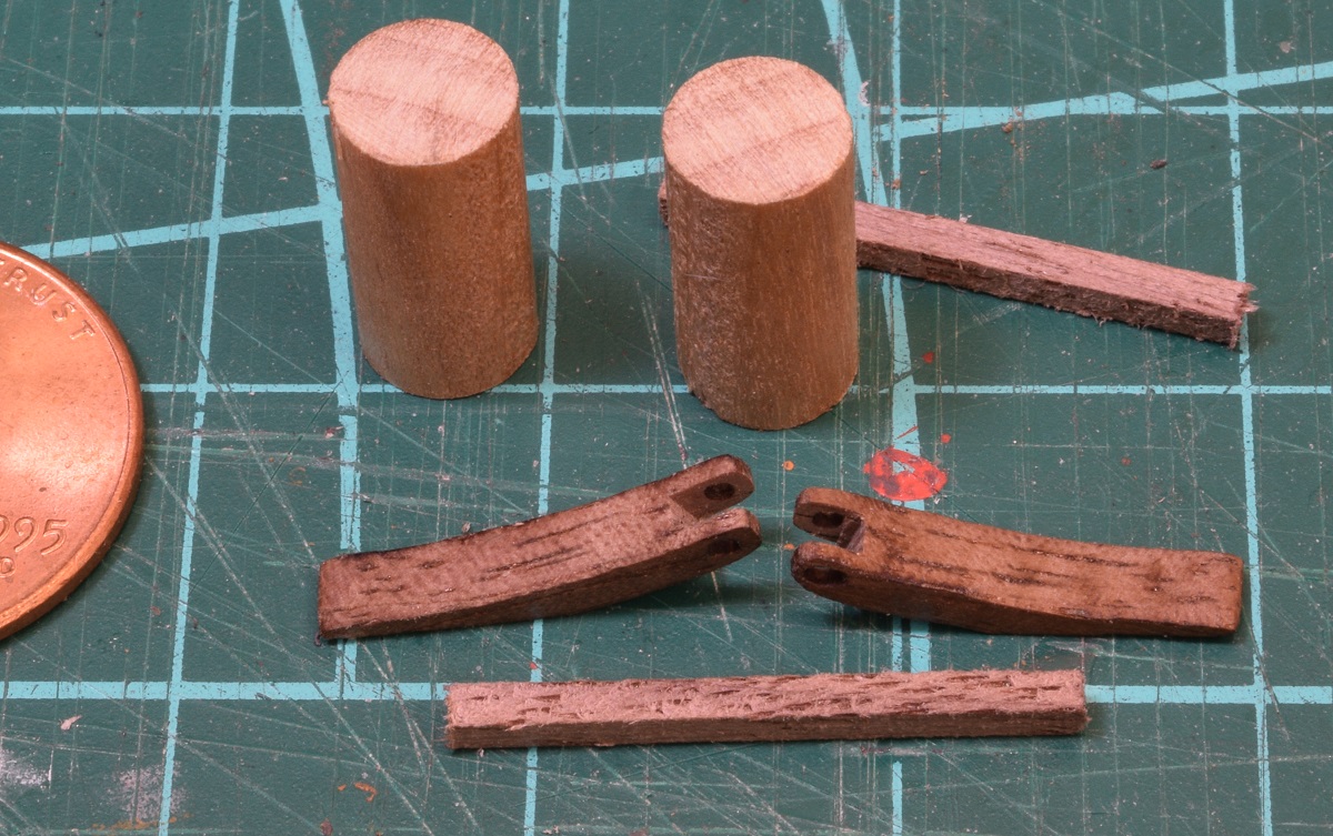 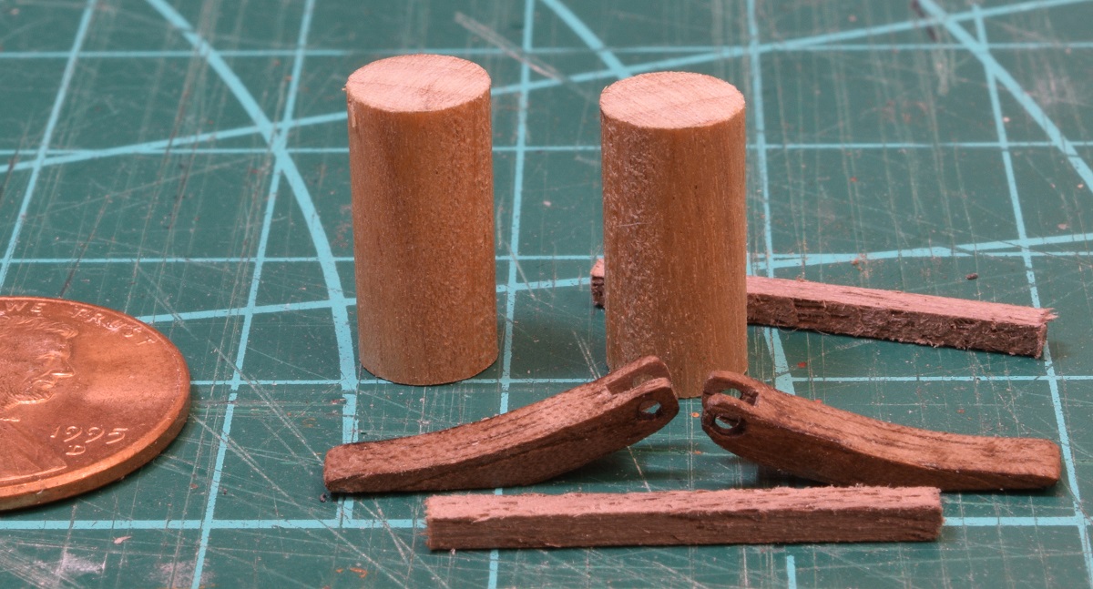 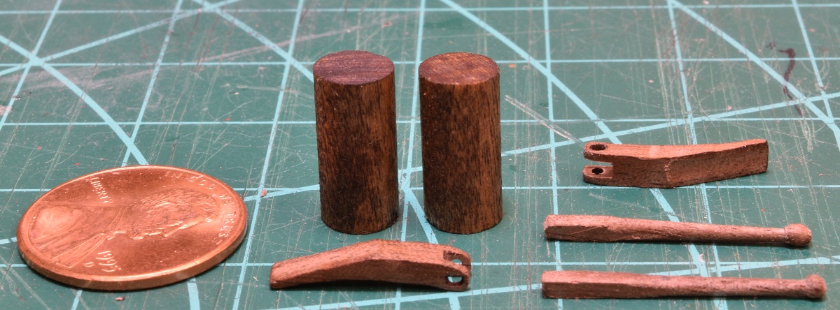 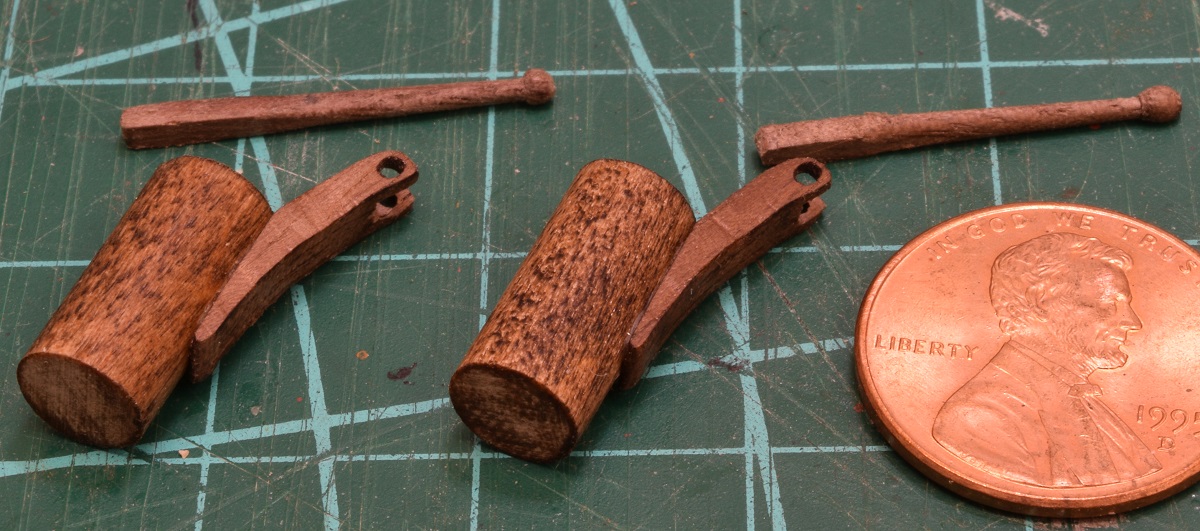 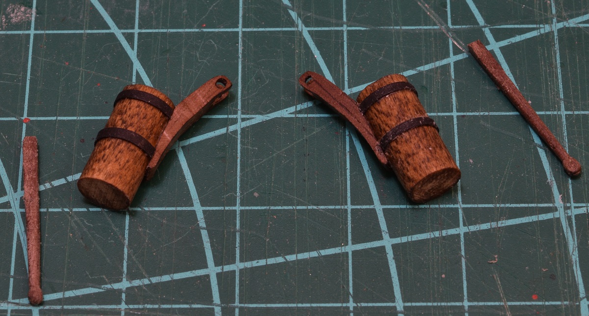 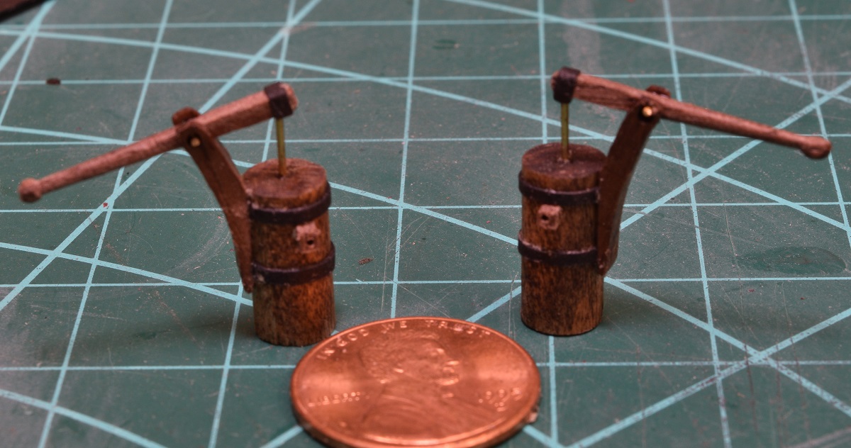 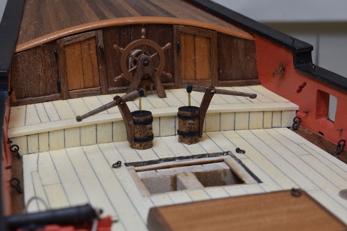 Now that the pumps are done, I finally installed the companionway in it's permanent home. 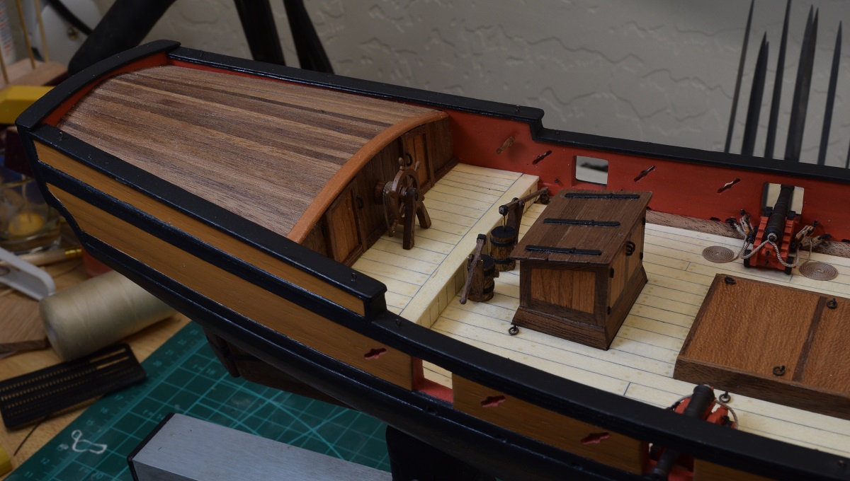 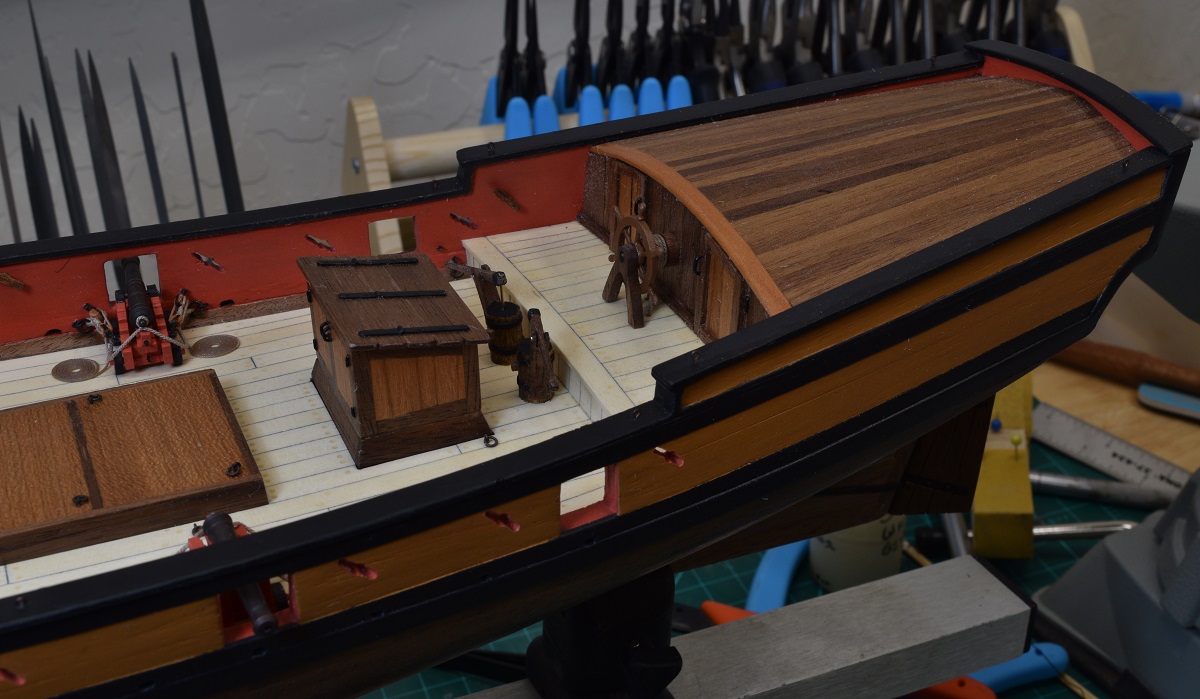 And then I buckled down and did it. All the guns are rigged. Woo! 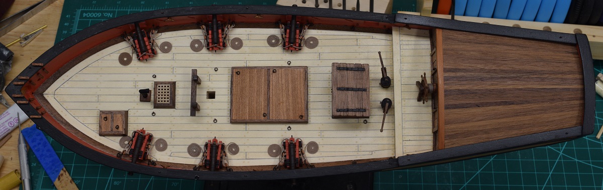 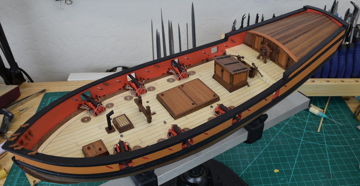 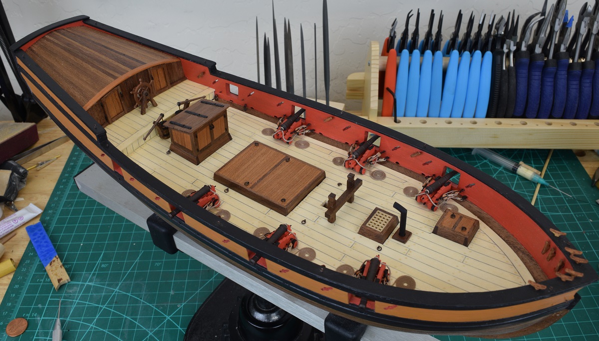 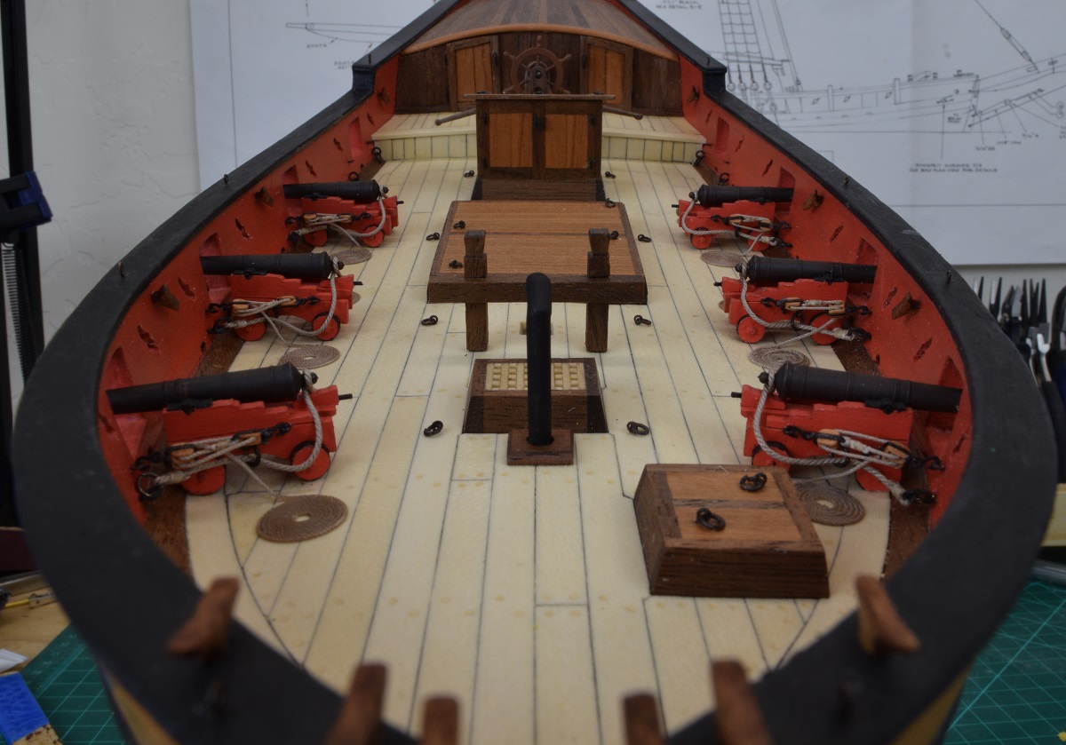 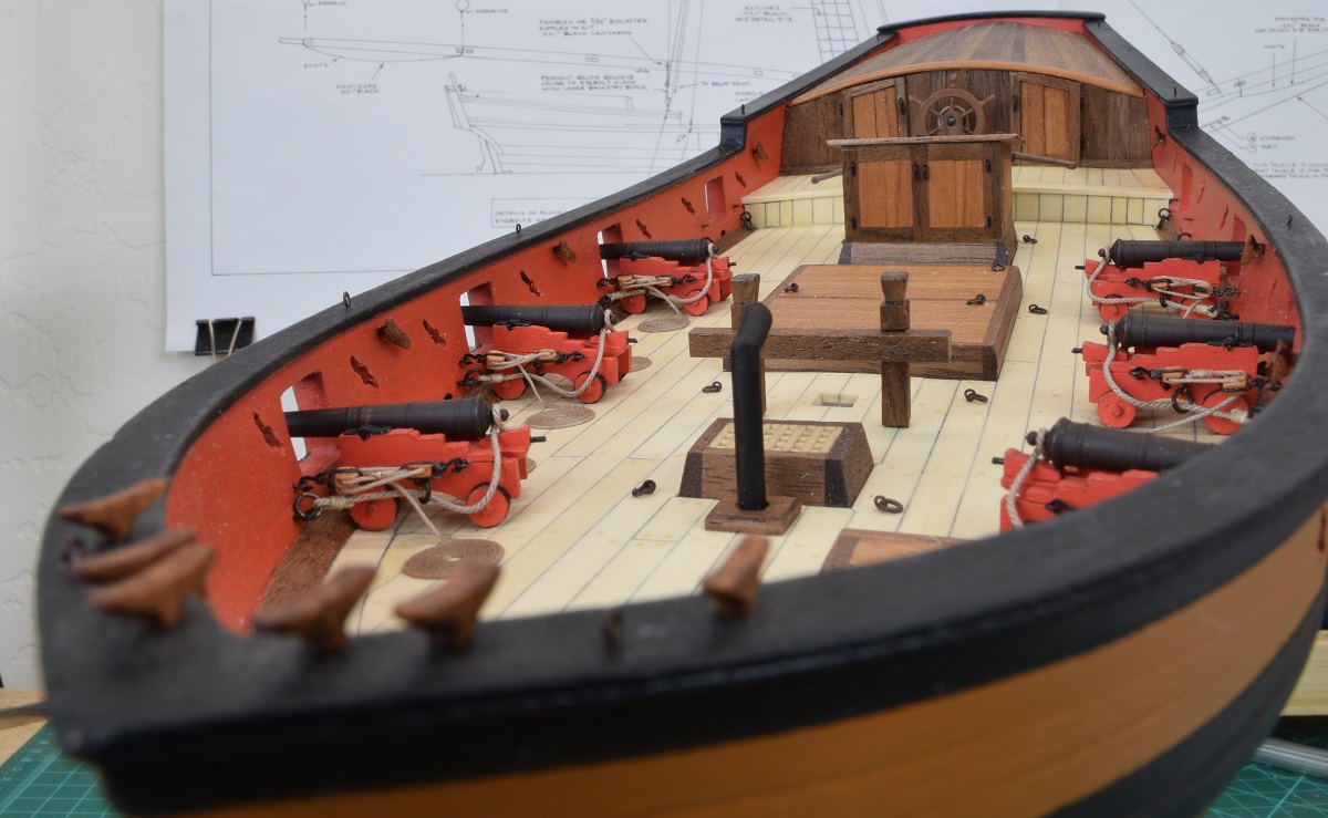 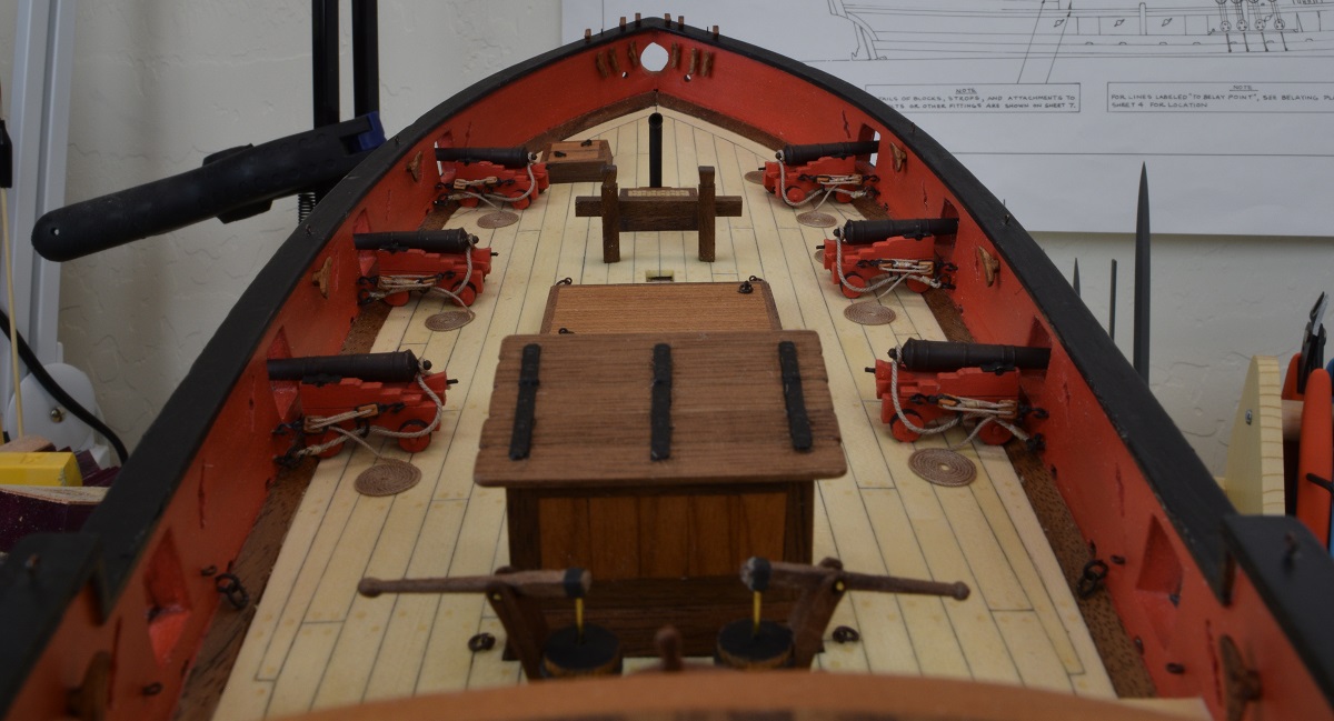 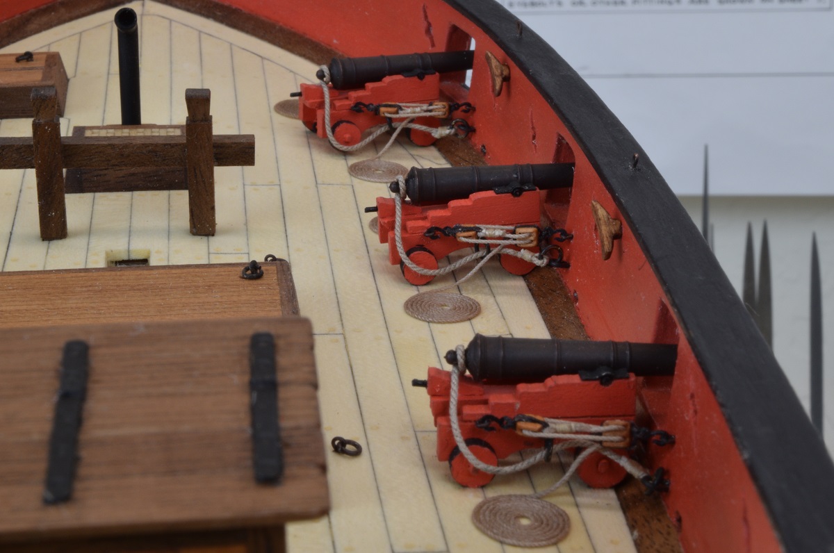 The catheads turned into an unexpected issue. The angle built into the laser cut parts appeared to be completely wrong. When the 'flat' on the bottom of the cathead was placed on the cap rail per the plans and instructions, the base was standing proud of the inside of the bulwarks near the deck by about 1/4". Not sure if they are cut wrong, or if I somehow managed to get the angle on my bulwarks that far off of what they should be. The solutions that I could think of were: 1) Cut an angle into the cap rail making the catheads stick up at an angle more severe than that shown in the plans. Issue being that I was not sure the cap rail had enough thickness to actually support that angle, and the base of the catheads on the bulwarks would be lowered, possibly enough to interfere with the waterway. 2) File the bottom of the cathead to make it fit, again causing a fairly steep angle, and presenting issues with how to shape the bottom edge of the cathead once that much of and angle was built into the 'flat'. 3) Modify the catheads by separating them into two pieces right at the corner, and changing the angle. Issue - getting them aligned properly upon re-assembly, and making the join neat enough to not be visible on completion. I eliminated #1 almost immediately, as if it didn't work right, I would have the problem of wrecked cap rails which would be a huge task to replace. #2 seemed to be a problem with the shaping and the angle both. So I went with #3. Using the UMM micro-saw, I carefully sliced the cathead into two pieces, right at, and parallel to the 'flat' where the cathead would sit on the cap rail. I then filed the piece that would go on the bulkhead, a little bit at a time, test fitting until I hit the right angle, and to keep the mating surface reasonable close through the entire process. I then drilled a small hole into the bulkhead piece, and inserted a small brass nail cut to leave just the pointy tip exposed. I then pressed the two pieces together carefully aligning them. The tip of the nail gave me a point to drill the hole into the top piece, and I then replaced the pointy brass nail with a slightly longer one cut to be a pin to help secure the two parts together. I took a picture after the first one was complete, overlaid on the one that was still unmodified to show how much angle I changed. 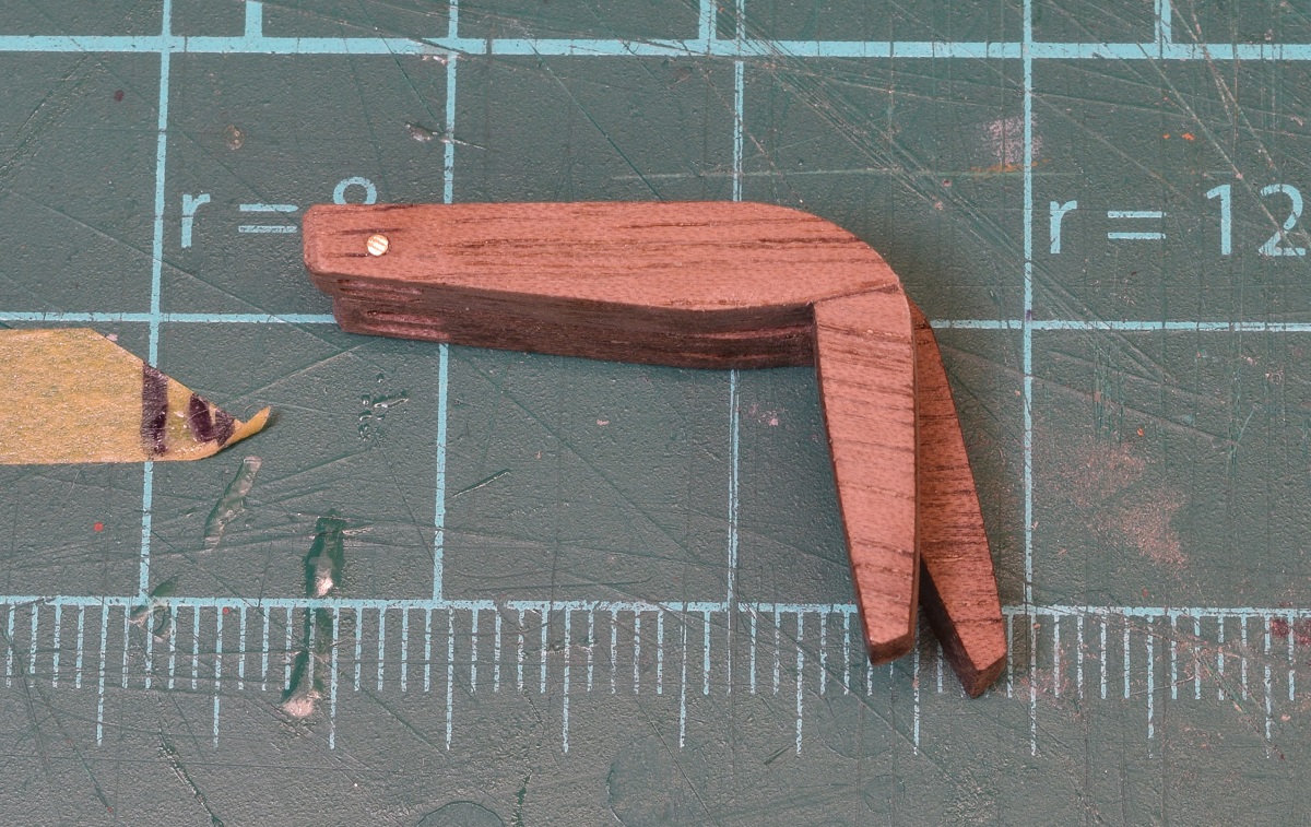 Seemed to work ok, so I cut the other one and followed the same procedure, and then mounted them both on the rail. Right after that I realized I forgot to drill the other hole in the cathead for the rope. Doh! So I carefully drilled out the other hole while supporting the cathead with a finger. 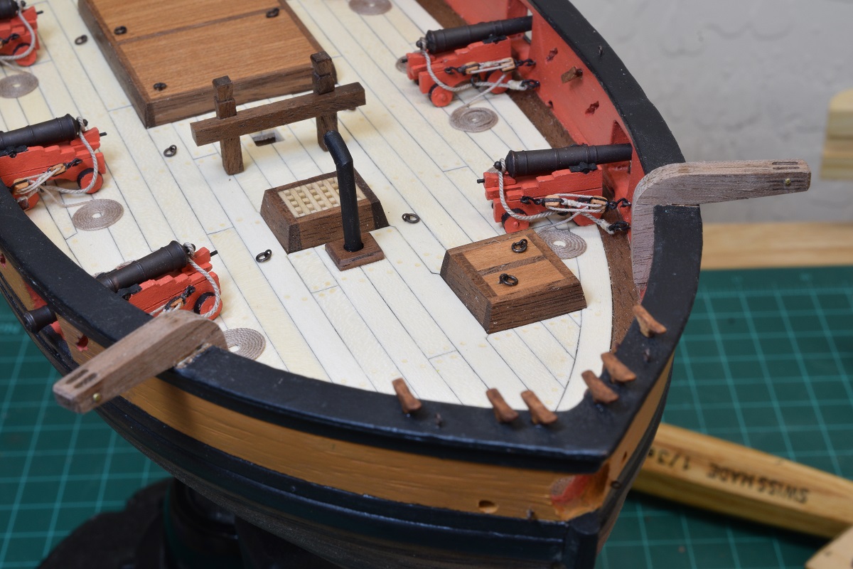 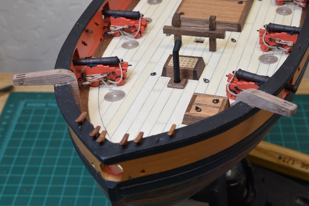 Issue resolved. I'll decide after I finish all the knightsheads and swivel gun supports whether these will be painted per the instructions or left natural, as I'll need to do a fair amount of touch-up painting where I removed the paint to get a good joint between the bulwarks / cap rail and the catheads.
|
|
#
?
Nov 11, 2020 20:42
|
|
|
After the catheads, I decided to make a timberhead, which came out pretty decent for my first try. Only made the one for now, need to make 5 more. I made this using a barret file for shaping. It's simply a piece of square walnut with the shape filed into it and then cut off, hole drilled in base and brass pin glued into the hole (not particularly straight either). Next up was the stairs. I made an angle in my little planking jig to make the ends parallel based on the bottom angle on the ladders, and then used the mill to cut groves for the treads. I'm not very happy with how they came out, but they do look much better just staring at the boat than they look in the pictures. I'll ponder whether to make some new ones to replace these. 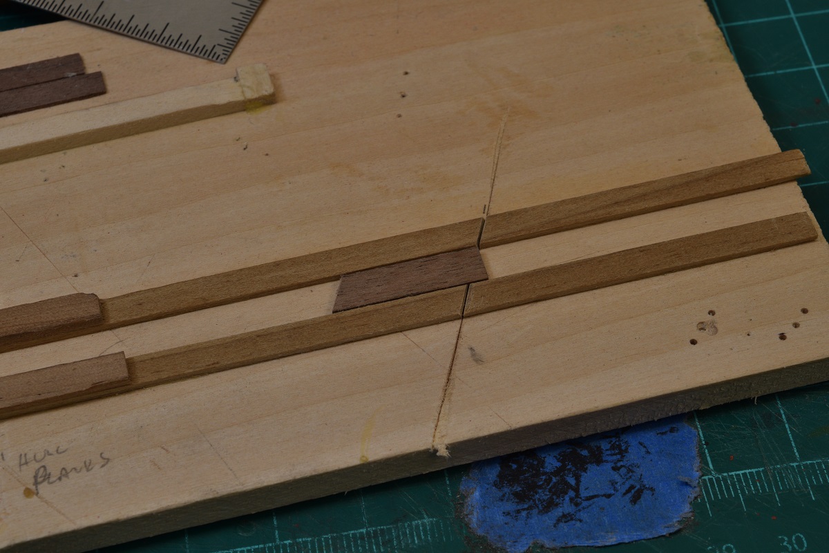 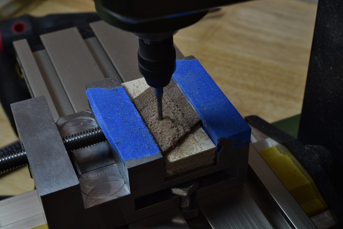 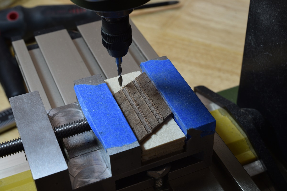 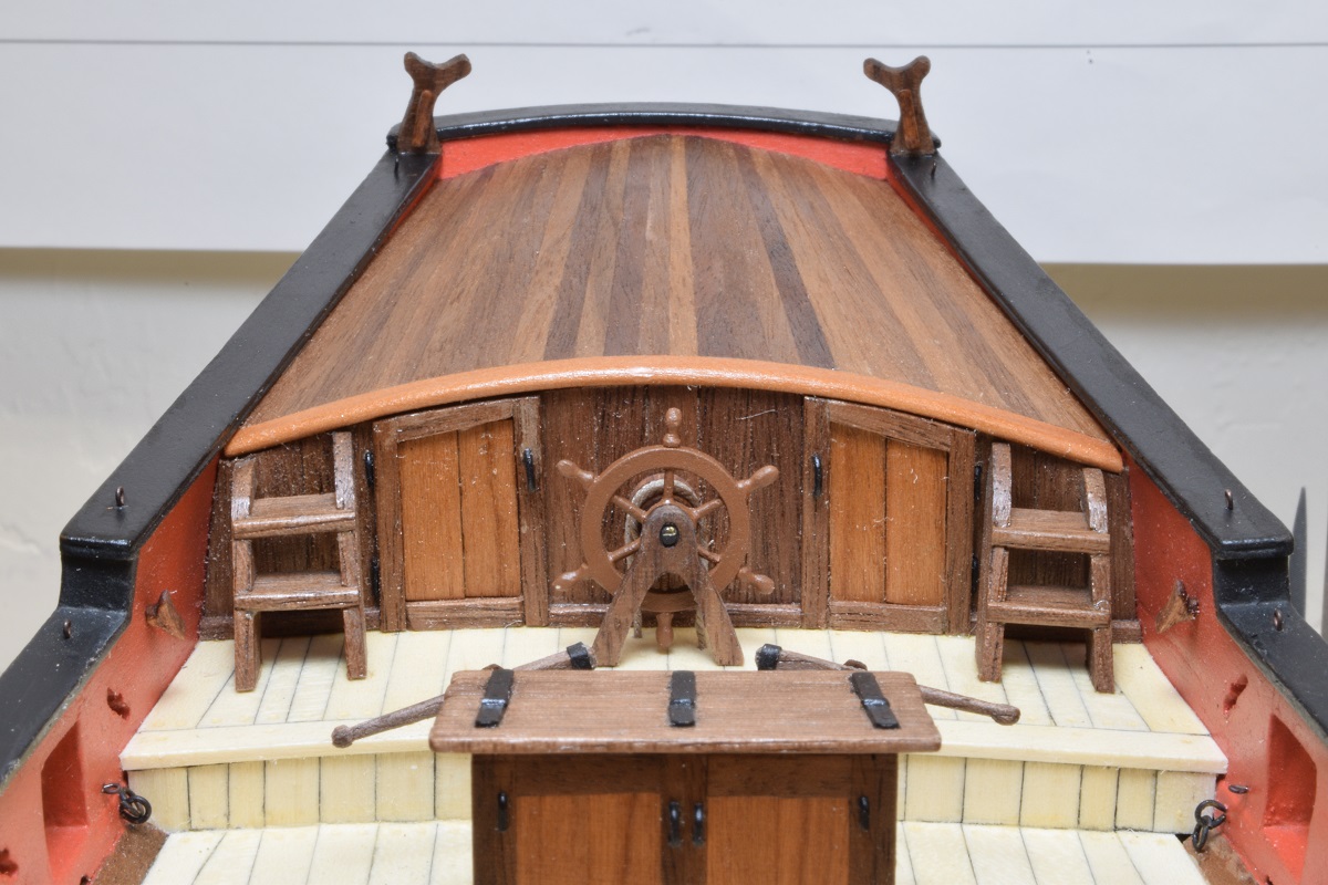 I then made and placed the boom crutches, which can be seen in the above photo (the sort of 'Y' looking things - the main boom rests on one of these when not in use, like when anchored or at dockside), and then assembled the binnacle. Fairly happy with how it came out, but I mis-placed it just slightly, but since it's pinned, I think it will stay here! Shots of the overall ship as it sits now, and close-ups of the binnacle. For some dumb reason I took no pictures of the assembly of the binnacle, but it's pretty much like the companionway, just a bunch of little bits of wood cut to size and stuck together. The binnacle has a place where the ships compass lives, protected from the weather, and generally there is a lantern inside to light the compass at night, which is why those holes exist on the top-sides, to let the heat/smoke out. The binnacle is also used sometimes for storage of signal flags or charts. 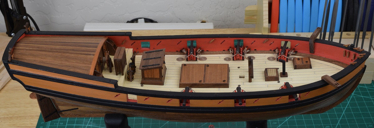 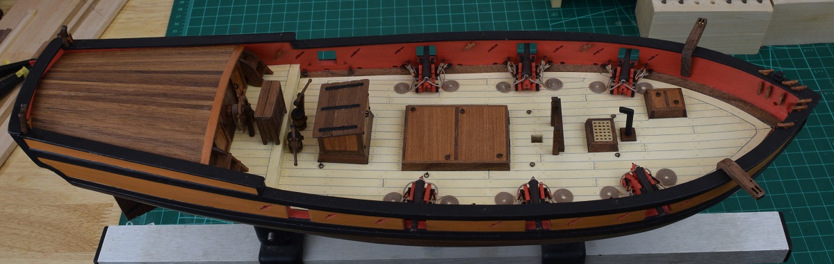 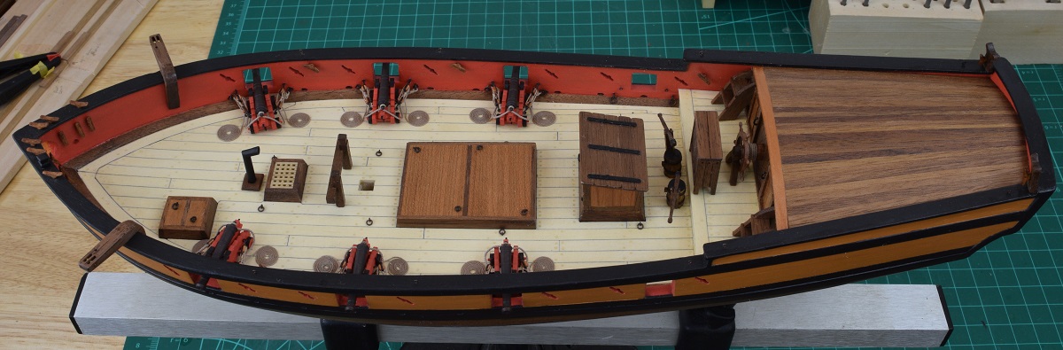 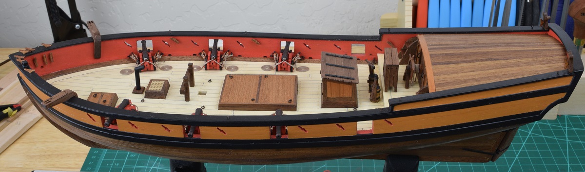 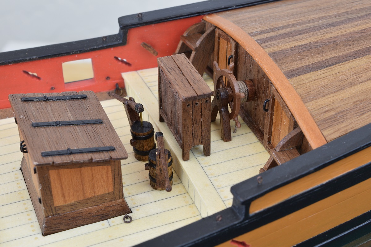 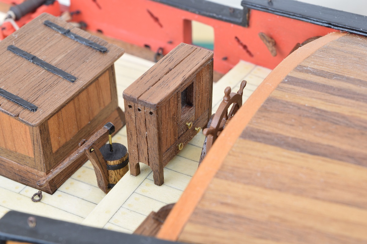 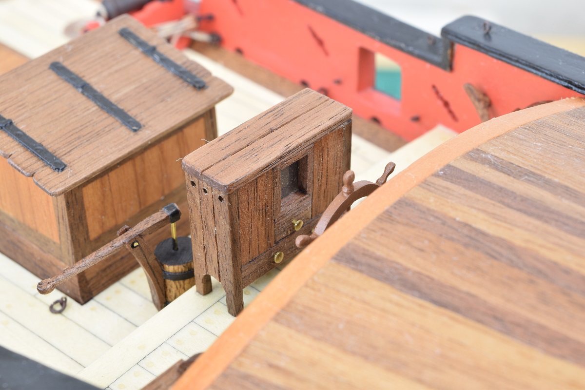 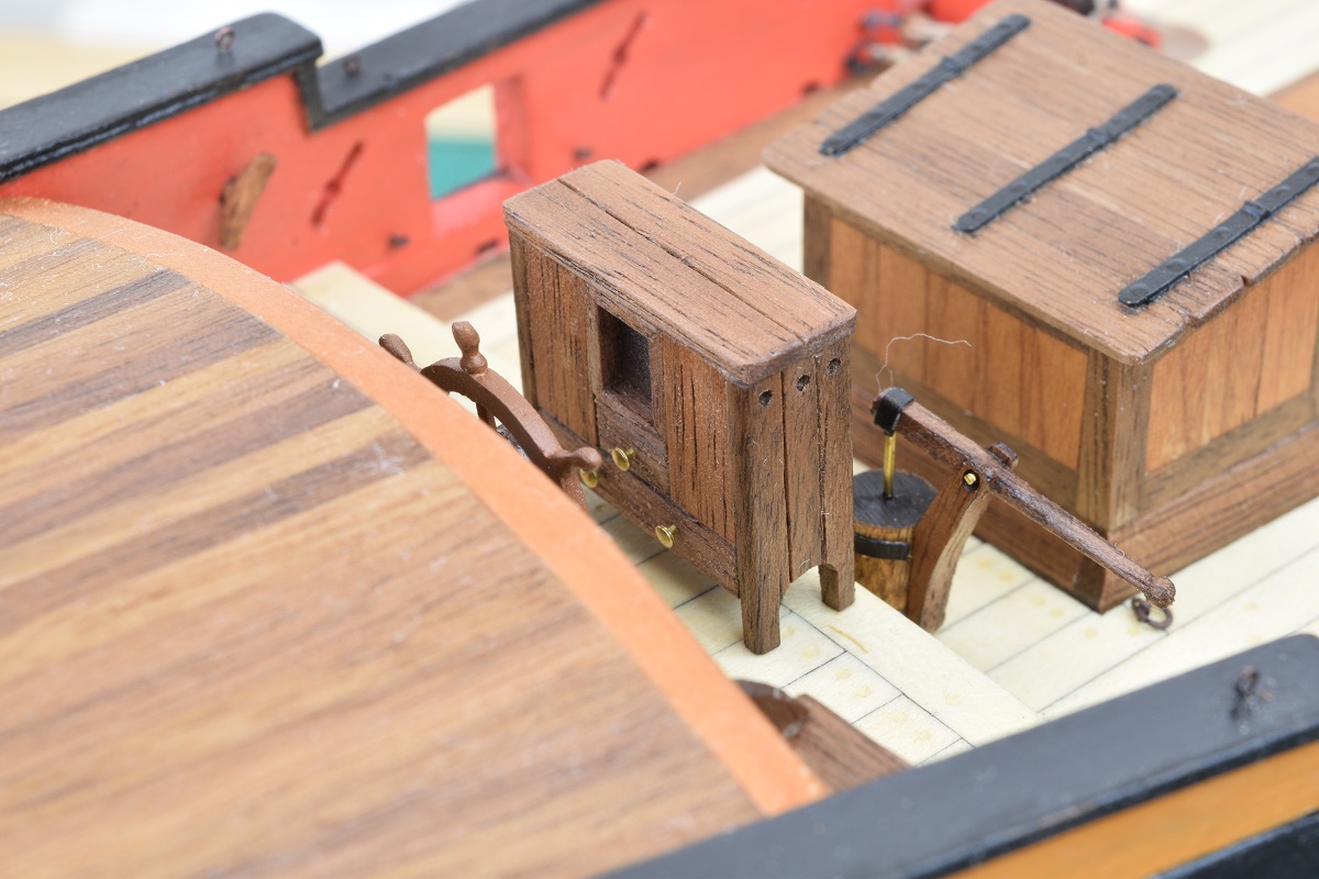 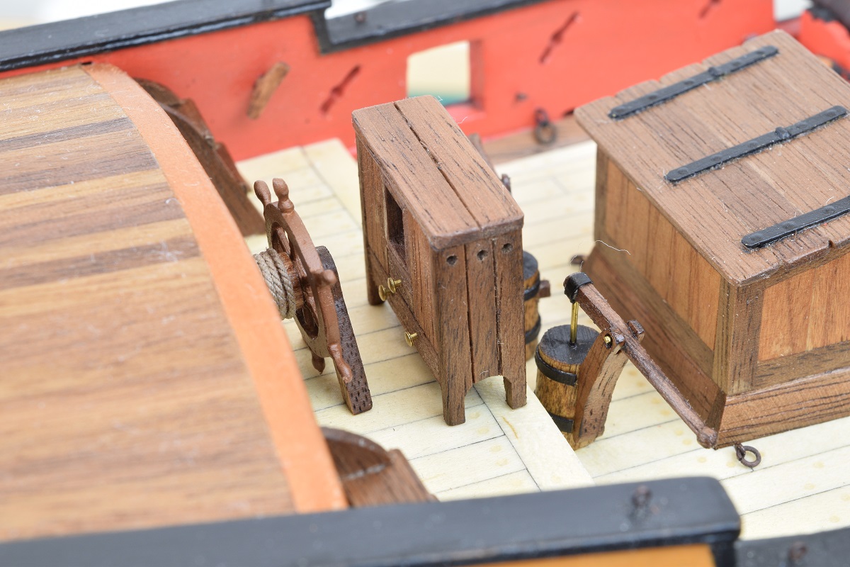 Still to go - 5 more timberheads, the pedestals for the swivel guns, and the channels and chain-plates. After that we start looking at masts and rigging!
|
|
#
?
Nov 12, 2020 01:46
|
|
|
As some (or all) of you may have gathered by now, I'm quite easily distracted by "shiny things". My most recent distraction was that I finally decided that I needed to finish my work room, which required quite a bit of re-working. First I removed the temporary hanging lights I had rigged, and spent far more time working over my head than I have done in a very long time, which reminded me that working on overhead stuff truly sucks. I used Wiremold to tap two circuits out of my overhead light fixture (was wired for a ceiling fan that was never installed in this room). I then hung 3 awesome LED light fixtures from Costco (3700 lumens each @ 4000K, for only a 30 watt draw), these are all wired to the same circuit. 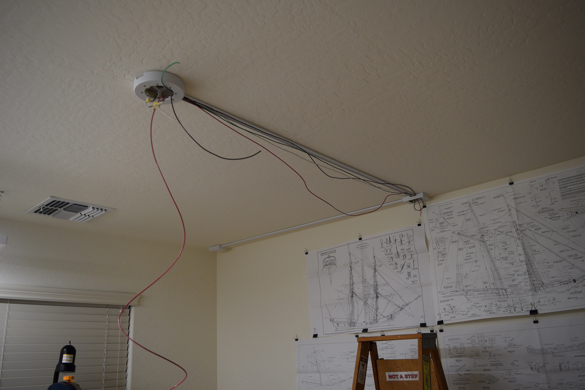 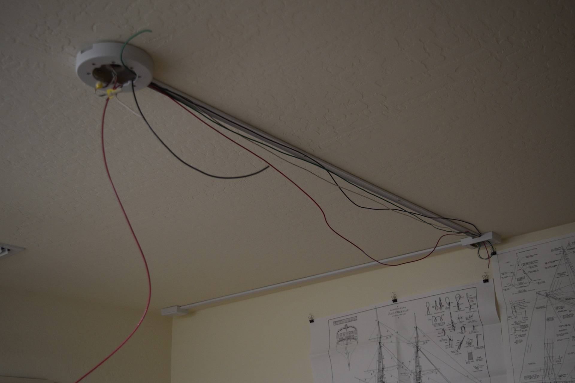 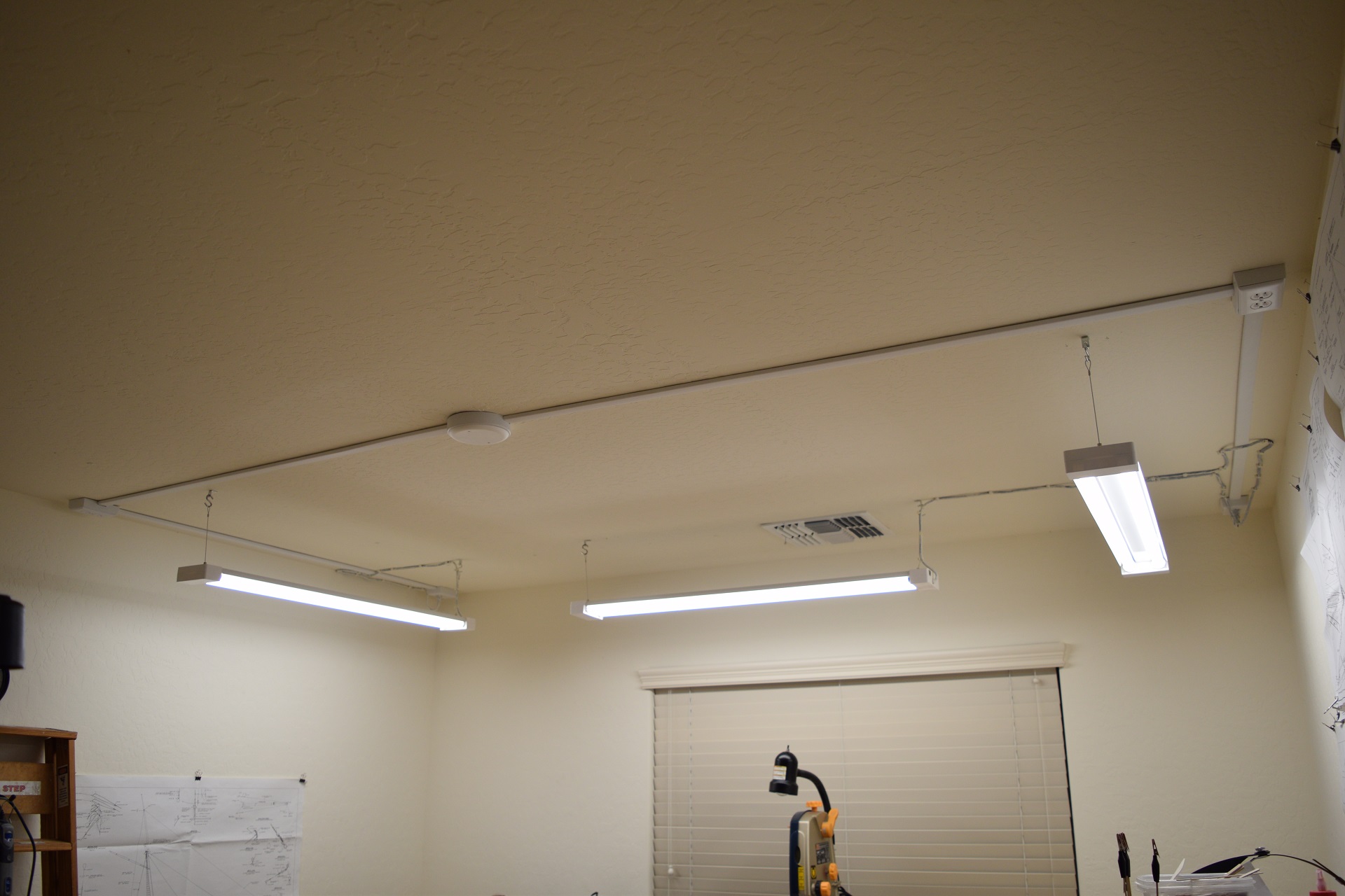 So much light, it's awesome. Next up, launched into a furniture assembling marathon, and replaced my two 20" deep, very crowded work benches with 3 x 30" x 60" surfaces, allowing me to move both existing work benches to the back side of the room and dedicate them to my ever-growing collection of power tools. Thanks to a friend for pointing me at Ikea for these fantastic table-tops and shelf units. 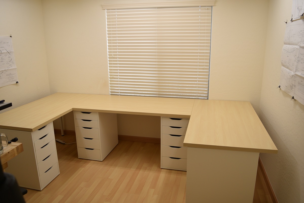 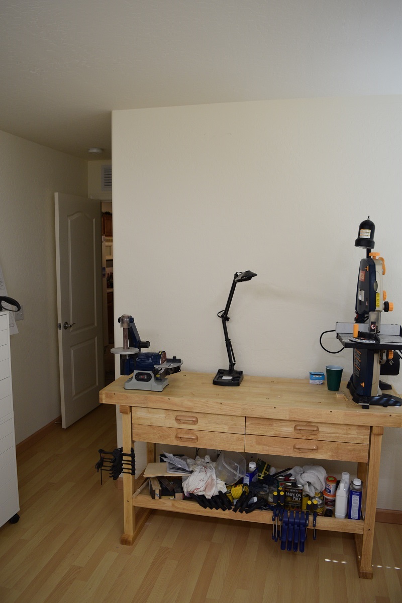 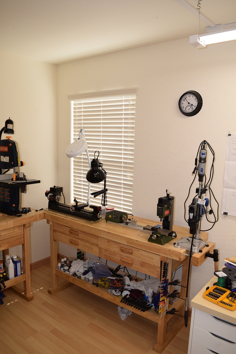 I still have to mount two more of these LED fixtures, which will be on the other circuit so they are separately switched over the two work benches, but that will come later. I've got a ton of work now just to get organized into the new area, since everything has to be relocated to the new drawer units under the new work area. I also added a big ugly black shelf unit from Lowes, and a pair of Ikea cabinet things stacked on top of each other to make one tall storage unit. 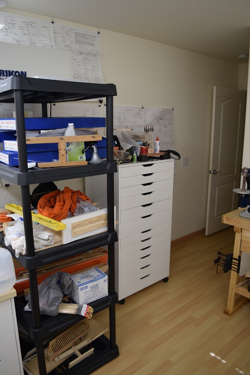 --------------- Ship update! After redoing the workshop, I got back to the final deck details prior to starting to work my way forward and upward! I completed the timberheads, swivel gun support posts, and the channels in preparation to begin the chain-plate fabrication next. The channels are the flat bits of wood that stick out from the side of the ship with 4 'notches' in them. You will see how these work to support the chain-plates (which hold the bottom of the main shrouds, which are the rigging that supports the mast). I point out these items in the final picture below. 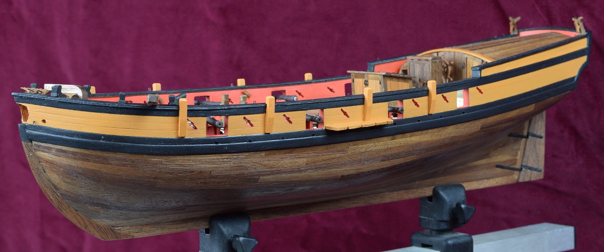 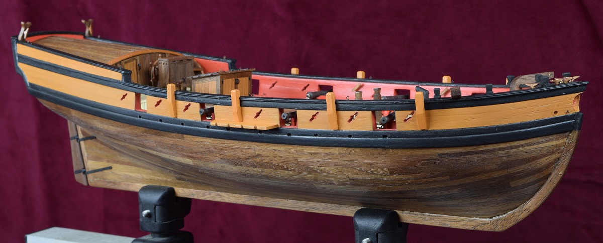 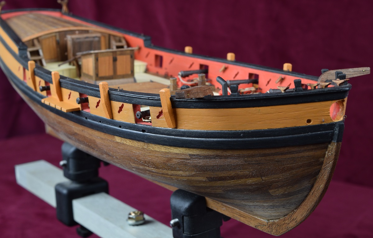 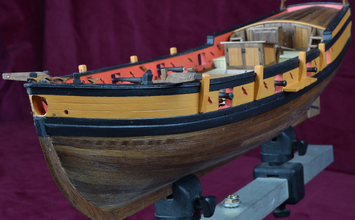 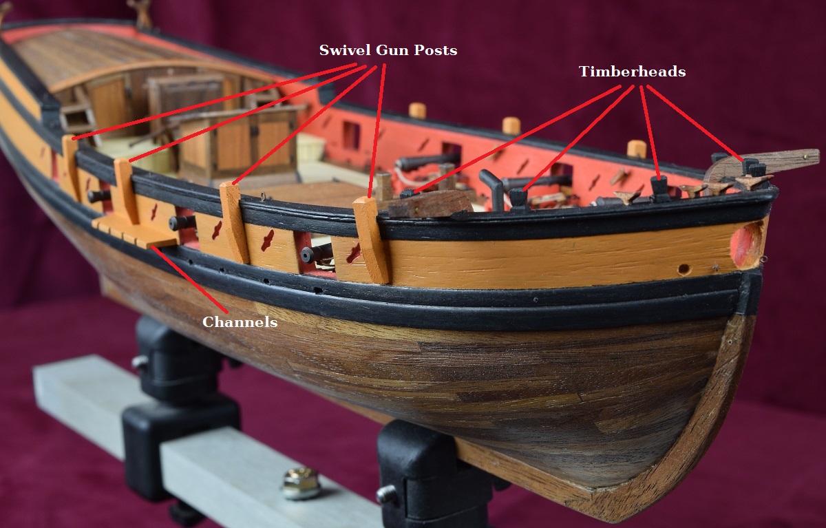 I think I'll make a dummy mast so that I can attach rope to get the angle on the chain-plates correct, and then make some sort of a jig (I've got some ideas from other build logs here) for positioning the upper dead-eyes later. I've decided to replace the kit dead-eyes with Syren ones, and I've got them assembled but not sanded yet. Also, after messing around again with the kit brittania cast swivel guns, decided to throw them out, and ordered brass swivel guns which I'll need to fabricate a yoke and handles for. ---------------- In order to get the angle for the chain-plates right, I cut a piece of basswood to the proper length for the main mast, then cut the bottom to fit at the correct angle, and built a step into the top at the height of the cross-trees. Using this false-mast, I could run rope around the mast to get the angle correct (hopefully!). 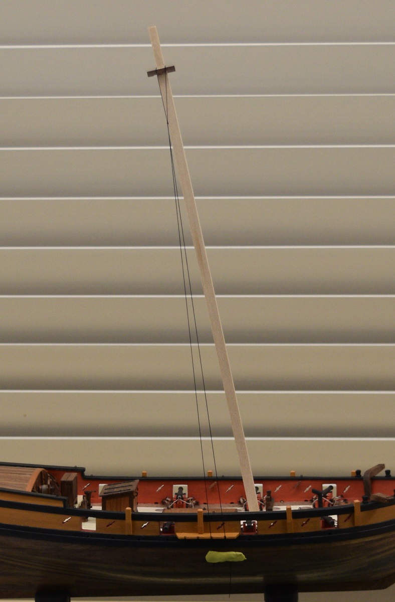 Yesterday, I spent a large chunk of the day doing touch-up painting, getting an extra coat of paint on all the new stuff I've added, so that I can put some poly on it after it's all dried. I then made bowsprit mark II (or is it III?). For the re-made bowsprit, I started with 3/8" square boxwood from Crown Timberyard, and first shaped it to a slightly oversized octagon using a lovely little jig that a friend loaned me on Saturday. Once I had that done, I shaped the base of the bowsprit, cheating heavily by using the mill, and then using the lathe, turned the round portion down to size at half-inch intervals, and then used 220 grit sandpaper, still in the lathe, to finish it to a smooth taper. I then used the cut-off tool to cut off the tip, which I then sanded to shape by hand. Finally, I cut off the larger square piece where it was chucked into the lathe, and completed shaping the base to the correct angle to sit on the fore-deck. Much happier with the improved mark II version. It's sort of hard to see in the photo's, but the edges of the octagon are much sharper, it's much more uniform, and the square foot is much sharper and better shaped in general. It's a very tight fit through the bow. In the photo's the original bowsprit I made from the wood I bought at Lowe's is the lighter one on top. 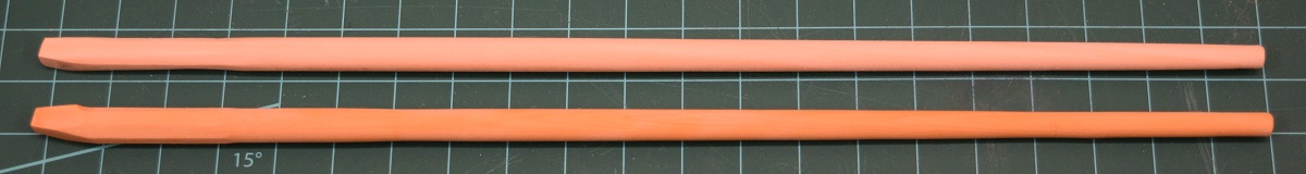 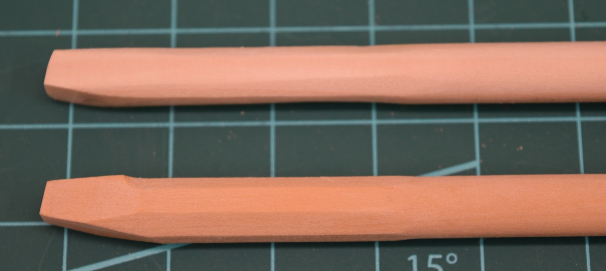
|
|
#
?
Nov 12, 2020 21:30
|
|
|
Probably a stupid question but, where is the pilot supposed to stand, to steer the ship? Do they stand to one side, so they can see past the binnacle and kinda hold the wheel on one side, or, do they stand between the binnacle and the wheel and face backwards maybe? Or have I got the scale wrong and they'd actually be tall enough to see over the binnacle?
|
|
#
?
Nov 13, 2020 02:01
|
|
|
Leperflesh posted:Probably a stupid question but, where is the pilot supposed to stand, to steer the ship? Do they stand to one side, so they can see past the binnacle and kinda hold the wheel on one side, or, do they stand between the binnacle and the wheel and face backwards maybe? Or have I got the scale wrong and they'd actually be tall enough to see over the binnacle? Let's just say there are a couple things here. First, it was very common in the age of sail for the helmsman to stand beside the wheel. Keep in mind that the 'wheel' was a pretty new thing to ships, and they were used to steering with tillers, which is a big wood bar attached to the top of the rudder and the helmsman would stand beside the tiller and move it back and forth (often moving to move the tiller far enough to one side or the other). Unlike many movies where the captain is standing at the wheel steering the ship, it was normally just some enlisted dude who had the job of wrestling with the wheel to steer the ship. In heavy weather the forces acting on the rudder were immense, and you would have one guy standing on each side. If you've ever seen the steering wheels of really large sailing ships, you know that they have two wheels with the barrel in between them. This is so that they could have up to 4 men manning the wheel when needed. Second, if you remember this ship isn't a model of a 'real' ship, but of a type. Well, the plans have some 'scale' issues (to say the least) in this particular area of the ship. A real person would have one hell of a time getting into those two little doors at the front of the rear cabin, because they are only about 3' tall in scale. I should have cut in sliding companionway tops over both of those, but I got lazy and didn't want to deal with it (they are not part of the plans). Here is a little piece of wood that I just put on the ship for scale. The model is 1:48 scale, or 1/4" = 1'. So the marks on that piece of wood are 1/4" apart and the entire piece of wood is about 6' tall in scale. Most dudes in the navies of the world were closer to 5' than 6', but still, that section of the ship has some scale issues.  Based on this picture, I apparently need to do some dusting too.
|
|
#
?
Nov 13, 2020 03:30
|
|
|
Gonna throw up another update as I'll be heading out for vacation so won't be adding to this again until late next week. -------------------------- I'm learning that I really dislike working with the metal bits. I'm not really equipped yet to do soldering on very fine parts yet (need one of those pinnable soldering mats of some kind), so I went with black coated copper wire to make the chain plates. I made a simple jig after getting the length figured out on a very rough not-pretty hand made piece. 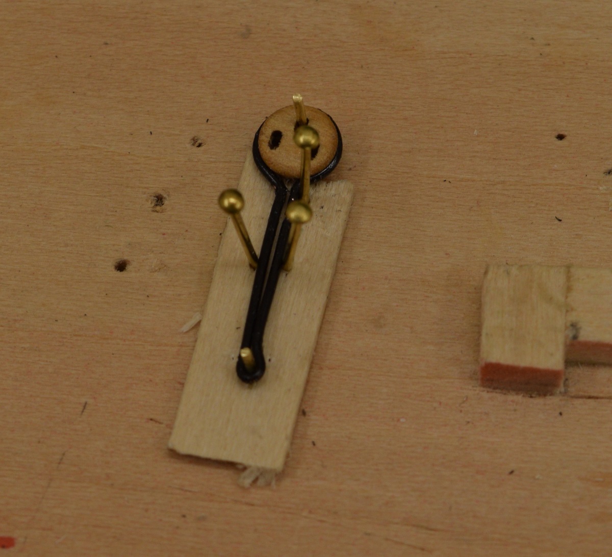 I test fit the first one and it was fairly decent, so I made all 4 for one side. 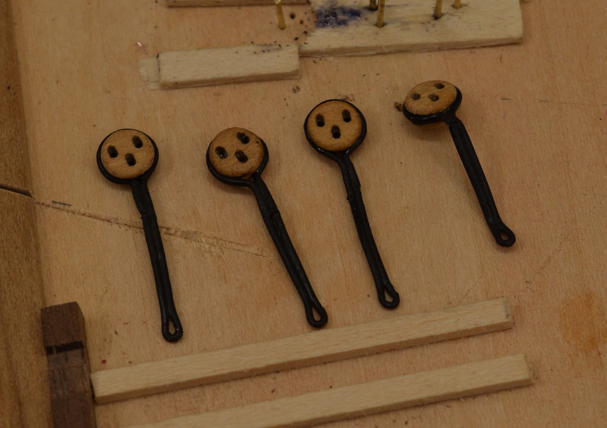 Then I bent them to fit the ship and.. I managed to flip the dead-eye in the jig on all but the first one, making them too long. I'll remake all 4 after adjusting the jig slightly and adding side pieces so that it's not possible to flip the dead-eye the wrong way. 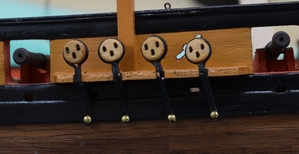 My system for these is quite simple, I'm making the joint where the cap of the channel will cover it, so the fact that it's not perfectly mated and soldered doesn't matter, and just joining the thing together with CA glue. This seems like it is going to work just fine, but I'll end up having to re-glue them all to keep them aligned after bending them to fit, as the brittle glue joint between the two sides tends to fail when I'm bending them into the channels. They'll also be painted matte black so they aren't shiny. If it doesn't work out, then I'll revert to doing something in brass, but I'm hoping this will work, as they seem to look just fine and once they are fixed in place with the nail/glue at the bottom and the channel cap at the top, they shouldn't be moving enough to be a problem. When I added the swivel gun pedestals, I completely forgot to drill the hole for the eventual mounting of the guns, so I needed to do the drilling while already mounted on the ship. I realized that this would be a smart thing to do now, before getting all the rigging in the way, so I had to decide how I was going to mount the guns when the time comes. As I've tossed the cast swivels in the proverbial trash can (I still have them, but am not going to use them), I will need to fabricate new mounts. I played around a bit and figured out what size of brass rod I am going to use, so from there it was a matter of how would I insert them into the pedestals. I chose to try something different, which may allow me to leave the swivels able to actually swivel. I cut off some very short pieces of micro-tube, which the brass rod would barely fit into, and blackened them. I then drilled holes into the top of the pedestals in 3 steps, using small drills, ending with a 1.60 mm bit to allow the blackened tubes to fit. Pretty happy with how they came out, and if I manage to make the mounts for the swivels actually decent (yay I get to practice soldering), I may leave them 'loose' so they can turn. I can always glue them in if I choose also. Here is a pedestal with the tube mounted. 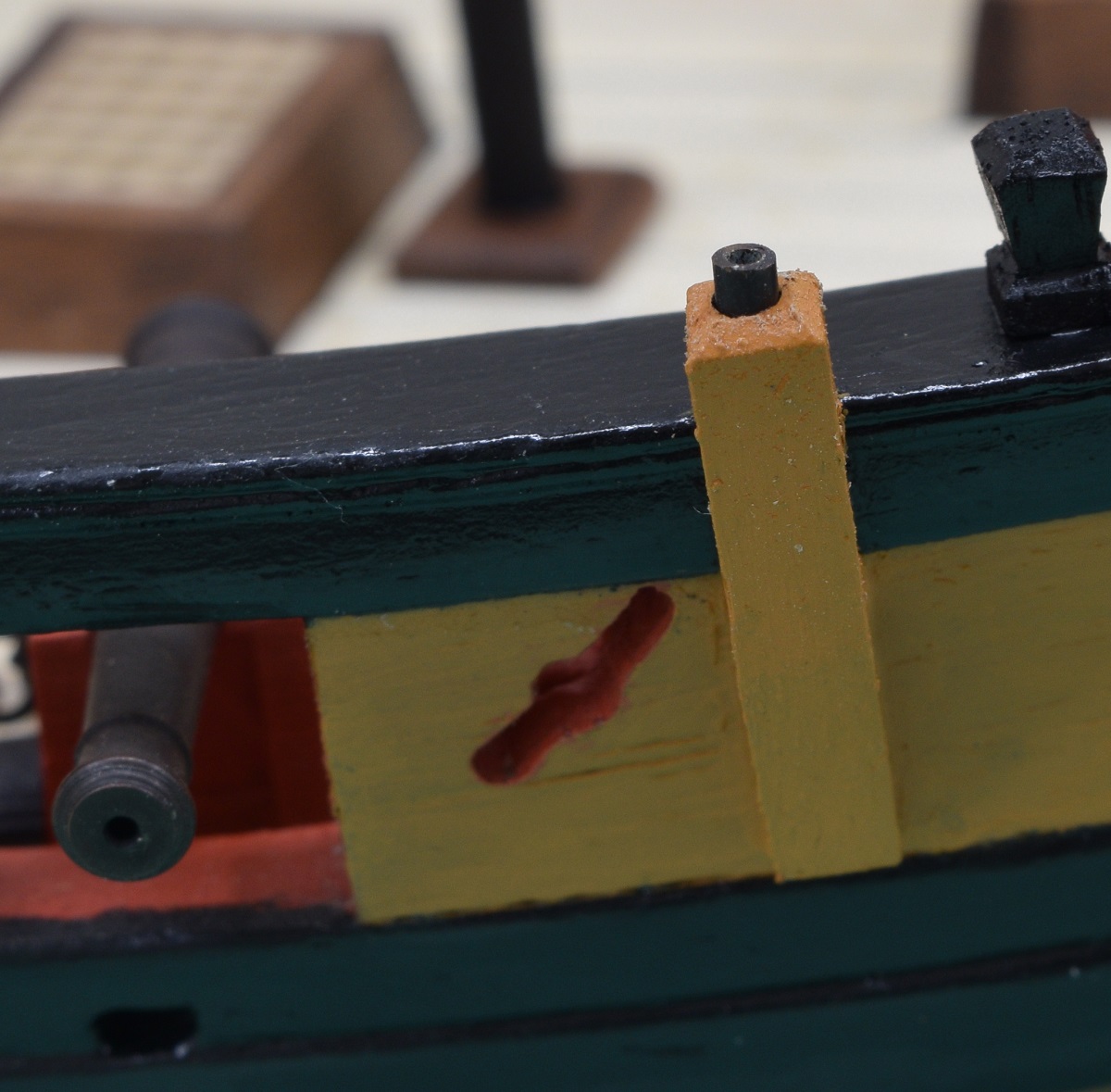 And here is a shot with the brass rod inserted to show how it will fit. 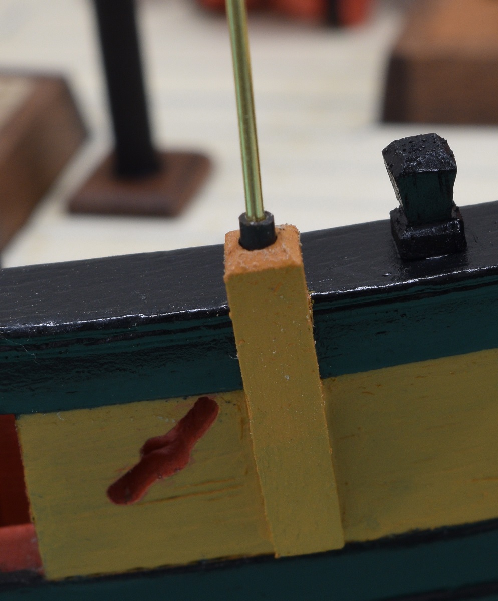 The yoke for the swivel mount will be attached to the brass rod which will drop into the tube. After that little side project, I went back and began remaking the chain plates. This time I chose to put the 'joint' at the bottom where it can be somewhat covered, or at least disguised a bit, by the nails I was going to use to pin the plates to the hull. They came out reasonably well, although by no means perfect. After initial placement, prior to painting. Way shiny (also this is massively over-exposed to show the plates against the black wale). 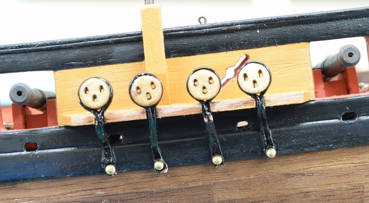 Massively over-exposed shot after putting the cap on the channel and first paint. 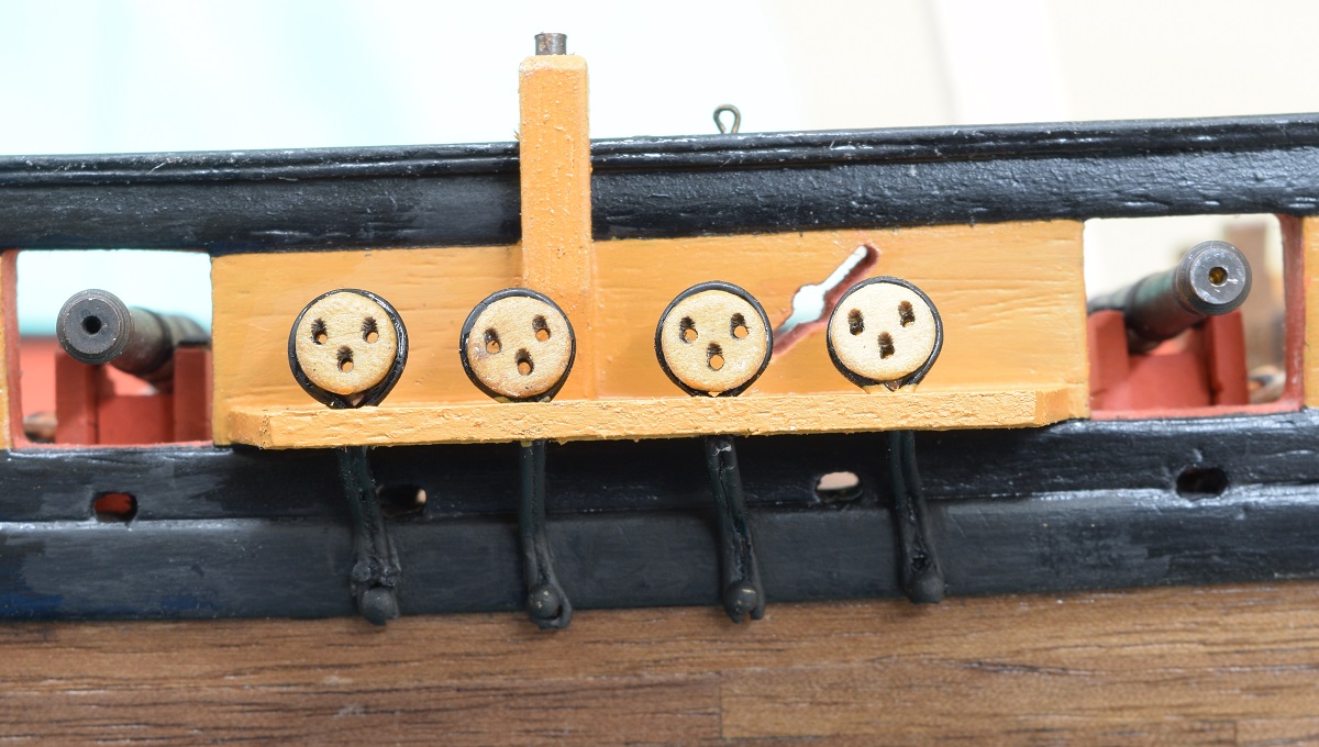 And a only slightly over-exposed shot showing more what the eyeball sees. 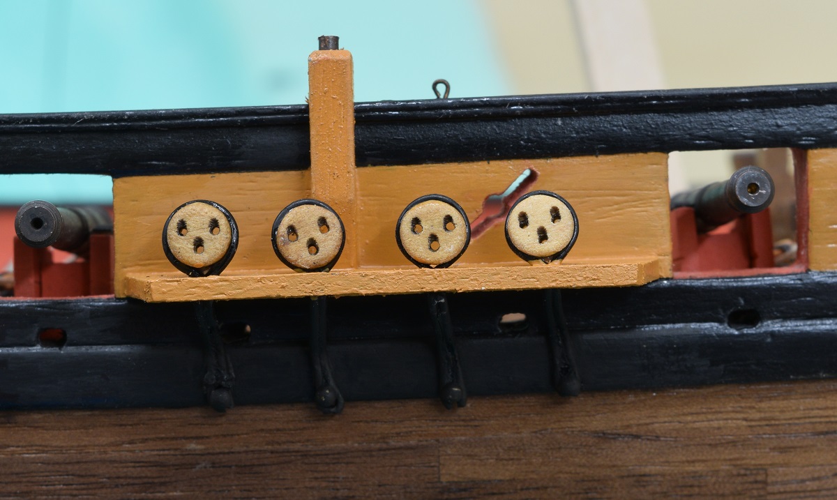 If I was doing this over again, I'd ignore the plan locations and put the holes for the base of the chain plates slightly further up, so that the bottoms of the chain plates wouldn't hang below the wale and make it harder to disguise my bad joint. In any case. The starboard side is done!
|
|
#
?
Nov 13, 2020 07:00
|
|
|
Loving this project! There's a modeller on youtube who makes stop motion videos of his builds, and he just put up a model ship: https://www.youtube.com/watch?v=2SuPPsyck2M The production values stand out more than the quality of the ship; I can't imagine how much more fiddly it would be.
|
|
#
?
Nov 15, 2020 01:26
|
|
|
Went to visit Fort Macon today and saw this, reminded me of your itty bitty cannons.
|
|
#
?
Nov 15, 2020 23:59
|
|

|
Back to the log posting... We left off with the chain-plates being installed on the starboard side, which means that next I should do the port side... But of course I didn't. Instead of finishing the chain plates and dead-eyes on the other side of the boat, I decided to play with power tools. The plans show a sheave in both the bowsprit, and the jib-boom, but the kit doesn't provide it, and both the plans and instructions say to just drill a hole for the line to run through. Well, the heck with that, I'm an idiot and decided to risk wrecking my bowsprit by building in the sheave! I am pretty happy with how the one for the bowsprit came out, I used a small piece of dowel with a hole drilled through it and sanded down to size for the pulley. 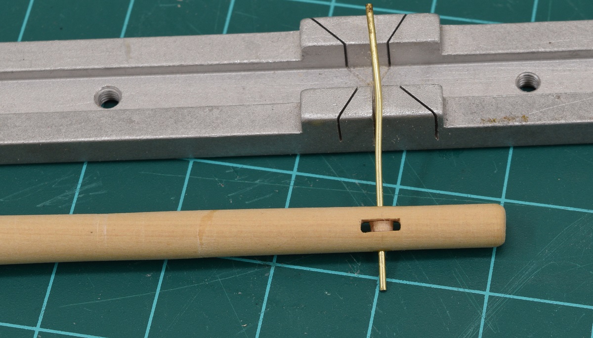 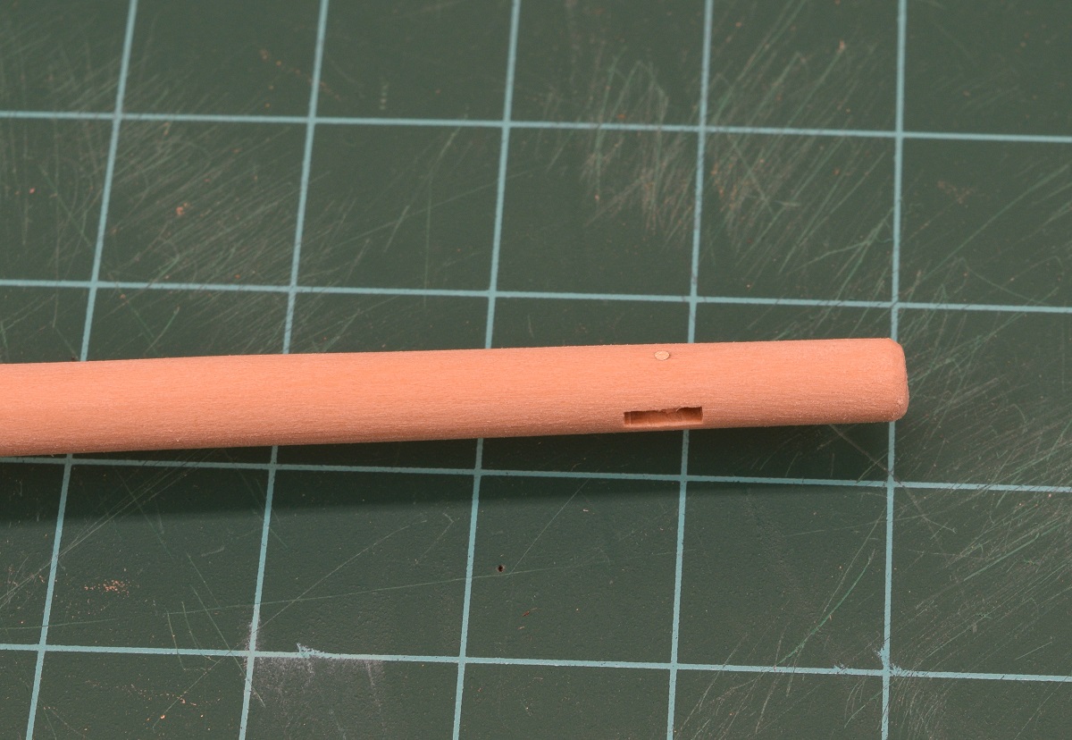 Not super happy with how the one in the jib-boom came out, it's just so small that I had a hard time getting a clean slot cut. I didn't even try to insert a pulley. I'm hoping that with rope run through this it won't look bad. Yes, it is still attached to the square stock that the jib-boom was lathed down from, that gets cut off and the tip shaped/sanded. 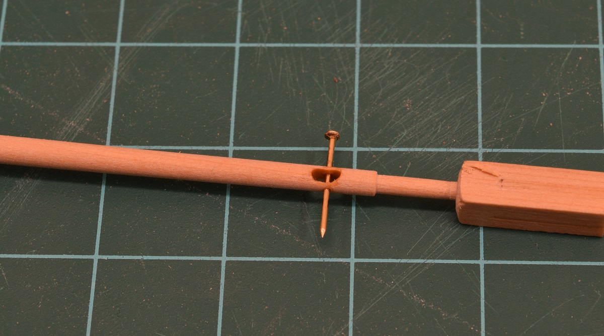 And here is a shot of the bowsprit and jib-boom together. They aren't actually glued together, I have a bunch of work left to do adding little cleats and stuff to them. Notice the length of this assembly is slightly longer than the length of the hull of the ship it will be attached to! 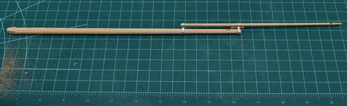 Then I made the main mast. This is the longest piece of wood on the ship, and was somewhat challenging to shape because it was so long. Pictured here next to the remainder of the 1/2" square boxwood that it was carved from. The other pictures are close ups of the top and foot of the mast. Pretty happy that I pretty much nailed the shapes and size on my first go at it. I do have 1 spare piece of boxwood if I had totally messed it up, but glad I shouldn't need to use it. 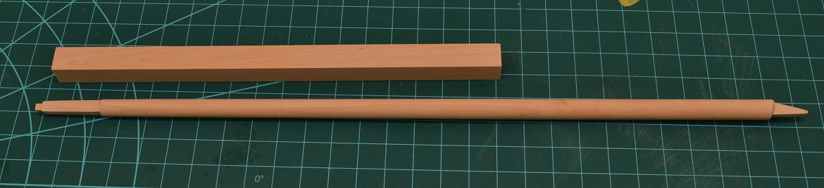 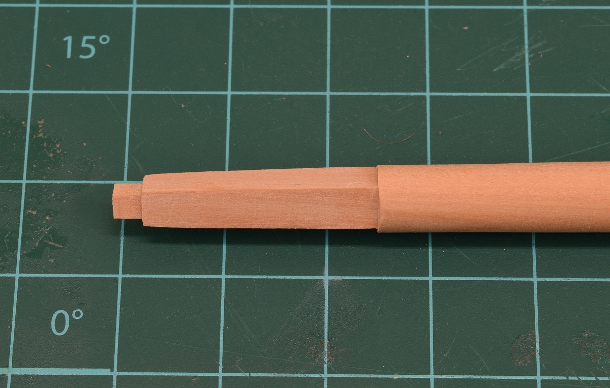 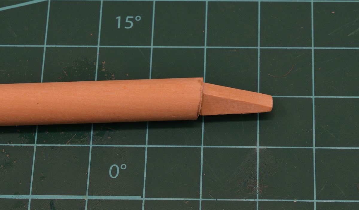 --------------------- As I continue to put off doing the chain plates on the port side, and have done some experimentation (failed) and various small bits. First, I decided to continue on my route of replacing most of the cast pieces in the kit by making my own mast hoops out of wood. Unfortunately, this didn't work out so good, as the wooden hoops are just too fragile, and I can't get them cut off without breaking them. This is partially because of their small size, and partially (or maybe mostly) because I was using a dowel as my wood, and the grain is just too big for this sort of thing. I have an idea on how I could make it work using multiple pieces of boxwood laminated together with the grain all going the proper direction, but in the end I decided that the effort just wasn't worth it for these pieces, and the kit hoops have been primed (and now painted as well, but no photo of that). Mast hoops are big rings that go around the mast. The main-sail is attached to these hoops allowing the sail to be raised and lowered. They work pretty much exactly the same as the rings a normal shower-curtain uses allowing you to move the curtain along the shower rod, but they are on the vertical mast instead of a horizontal bar.    The next cast piece to get trash-binned was the strap that holds the foot of the bowsprit. This piece doesn't fit the bowsprit properly as I completed it, and it's kind of ugly anyway, so I made a new piece out of brass. This is 5 pieces soldered together, which was quite a trial, as the pieces are so small I couldn't heat one joint without breaking another one. In the end I got it done, it's not perfect, but it will do. I drilled holes for brass pins that I will make to pin the strap to the deck, and to the bowsprit. I then blackened it with Birchwood Casey Brass Black, as I can no longer get Blacken-It at the local shop.  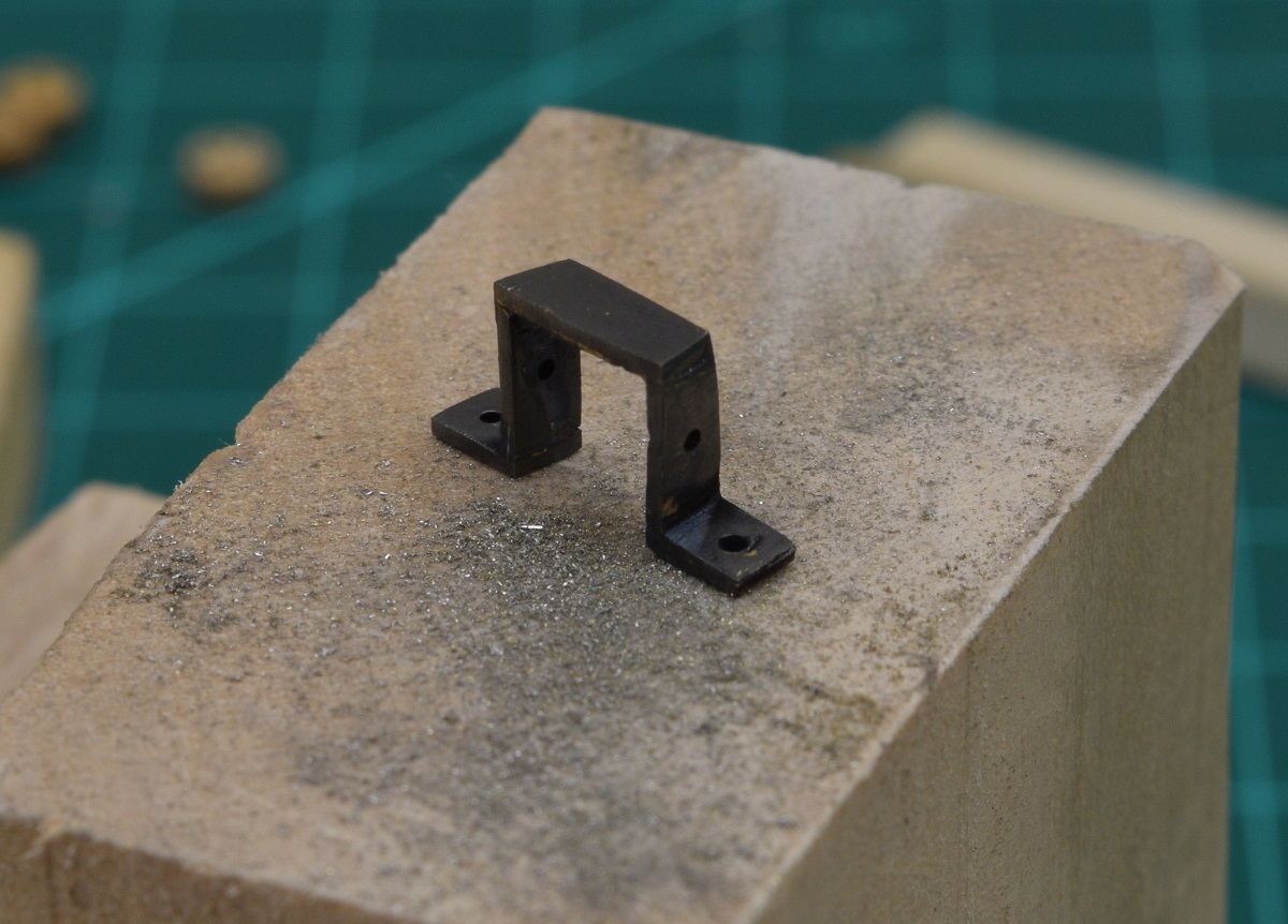 I got the mast wedge filed to fit the mast, and rounded the outside edge. Haven't decided yet on any detailing for this piece. The mast wedge on a real ship is composed of two things. 1) A bunch of small 'wedges' that are used to firmly keep the mast located properly in the hole through the deck, and 2) some kind of sealer that is used in combination with the wedges to prevent water from pouring into the hole. The sealer would often be tarred canvass or rope I believe. 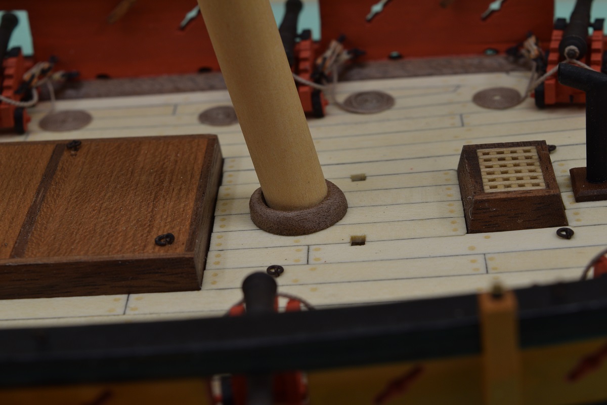 And finally, tossing the cast swivel guns into the bin, I started work on the replacements. First I soldered the trunions in place, and began to form a 'yoke' to support the gun. The trunions are the pieces that stick out either side of a cannon barrel and support the weight of the barrel. They are also a pivot point allowing the elevation of the barrel. 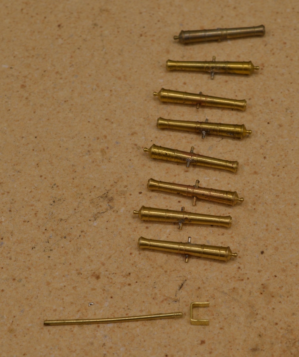 I then soldered the yoke to a rod, drilled holes for the trunion, and stuck a gun on to see how it will look. 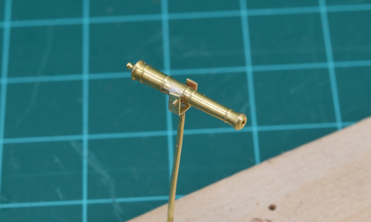 Pretty happy with how these look. Worth the effort and expense. 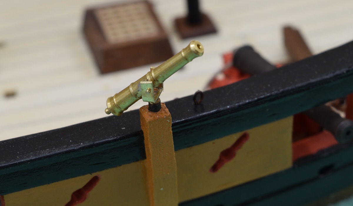 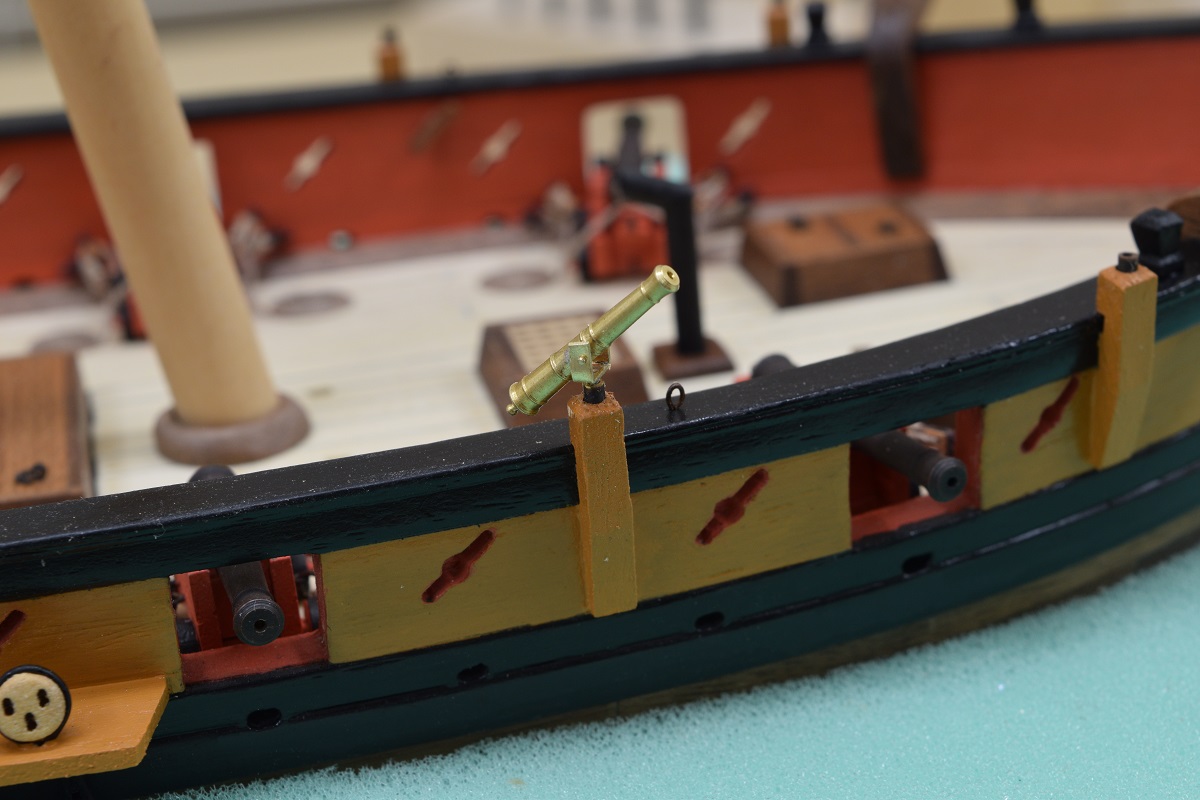 I will also be adding a handle to the gun. I sort of completely forgot to do that.
|
|
#
?
Nov 19, 2020 18:54
|
|
|
Grumio posted:Loving this project! I actually watched that video just a few days before I left on vacation. I do like his video and how he shows parts moving into place and stuff, although I had some issues with some of his methods, but that's just my OCD 'QA' personality doing it's best to critique everything I see. He certainly built a nice looking model and it was cool to watch. Slugworth posted:Went to visit Fort Macon today and saw this, reminded me of your itty bitty cannons. The little brass guns in my previous post are 'swivel' guns as your picture shows, or at least something similar. The main guns on the deck of this little ship are only 4 pounders, i.e. they shoot a 4 pound round shot. So they shoot a ball that weighs 8x as much as the little half-pounder in your photo. The 4 pounder was one of the smallest 'main' armaments on sailing ships of the day, although I have seen references to 3 pounders. Probably the most common size on the smaller ships was a 6 pounder.
|
|
#
?
Nov 19, 2020 18:59
|
|
|
Finally at a point where I am getting to 'visually' see how big this little (not so little) boat is going to be when it's completed. First I finished up the bowsprit by affixing a bunch of little cleats and sanding them to shape, and affixing the rings that support the jib boom. Bowsprit & Jib Boom: 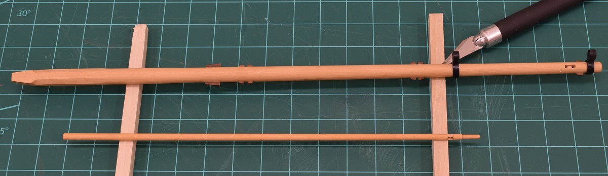 Next I mounted the cheeks and cross-trees on the main-mast, then put two of the chocks in, and made the third chock. After playing with the fitment of the third chock, and looking at the plans, I realized that the base of the topmast wouldn't fit through the round fitting at the top of the main-mast, so I removed the third chock and will place it after the topmast is placed permanently later on. I then made the topmast and cut the little hole in the base where a piece of wood called a 'fid' goes through it to rest on the cross-trees. I drilled a sheave slot in the top-mast, but haven't drilled the hole and placed the sheave yet. Here is how the main-mast and top-mast will fit together. Really happy with how this came out. 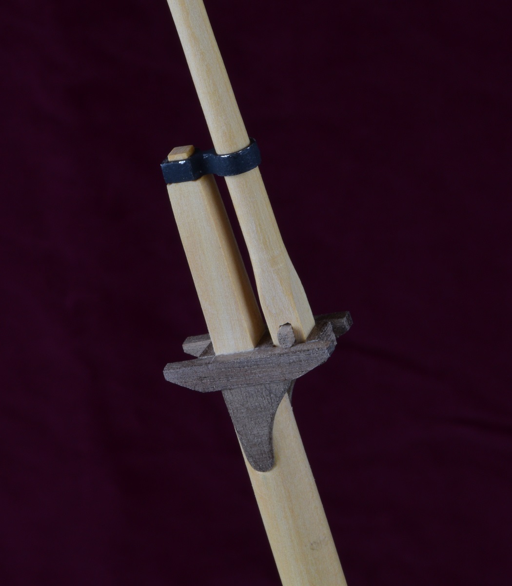 And finally, dry fitting the complete bowsprit and mast assemblies to see the overall size (minus the main boom which will extend behind the ship by several inches too). 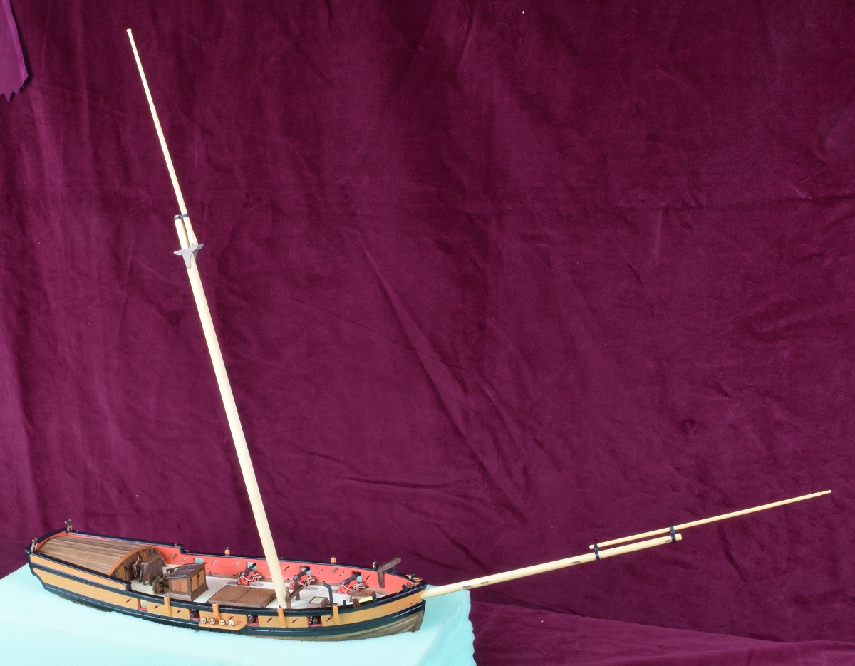 It got big all of a sudden! After this test fitting, I continued to work on and have completed the main-mast. 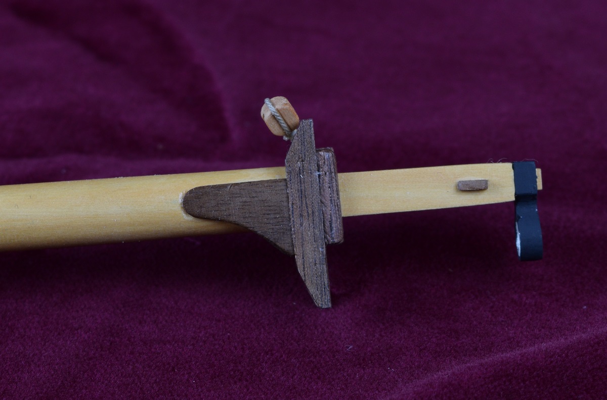 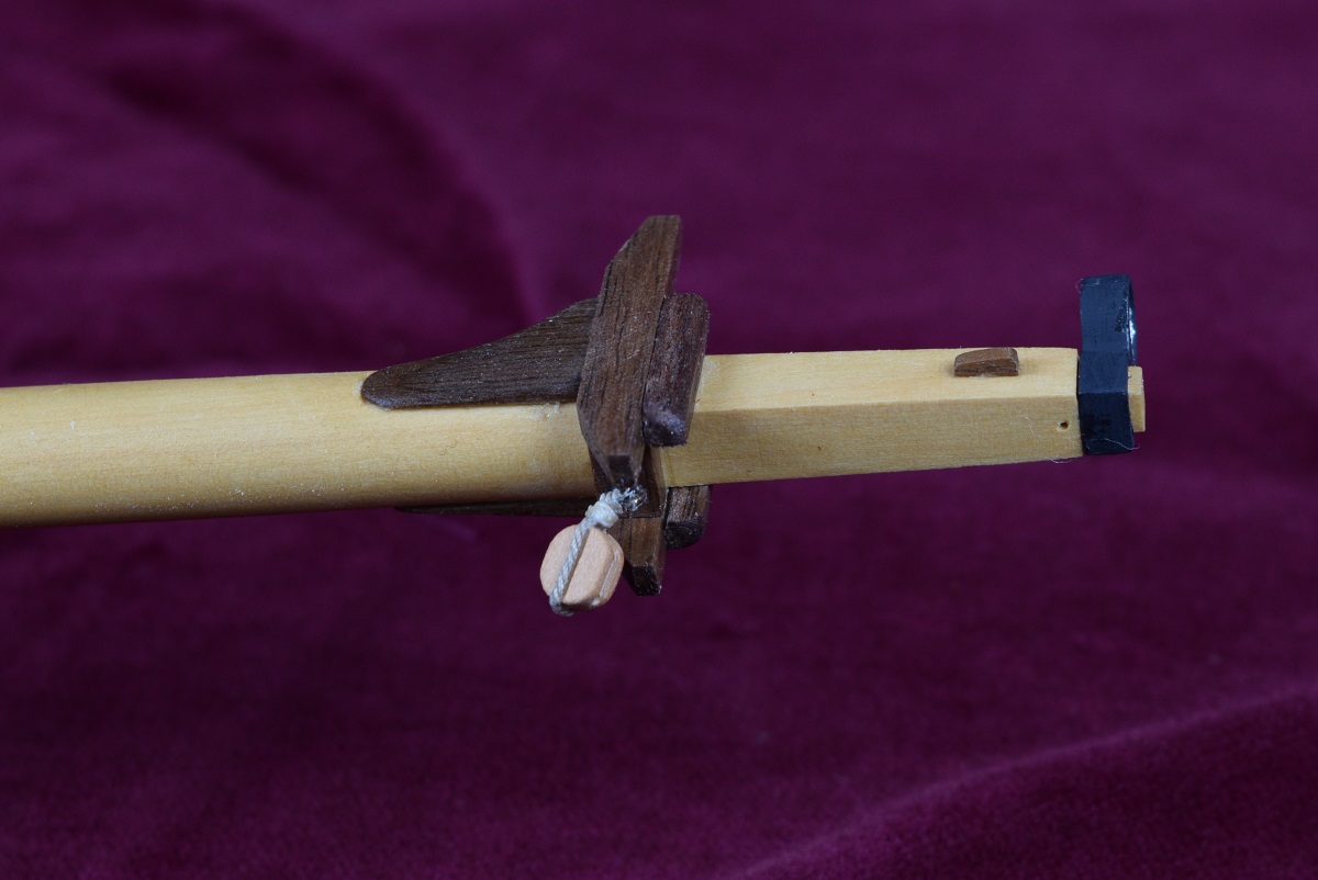 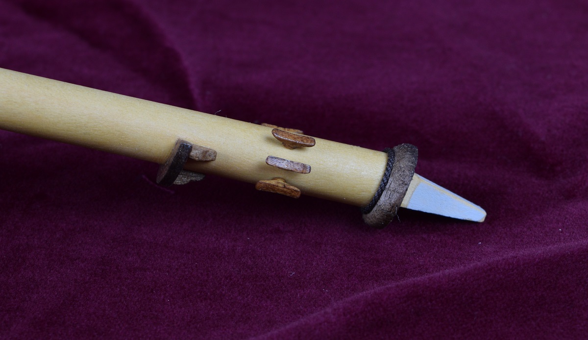 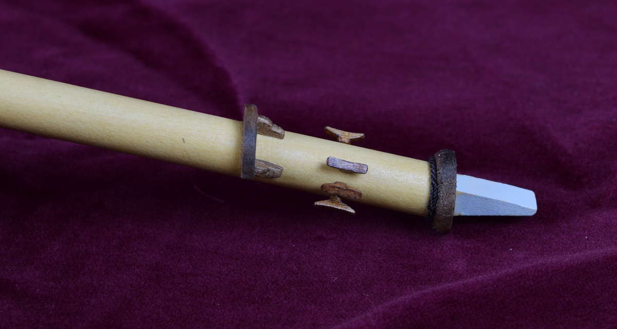 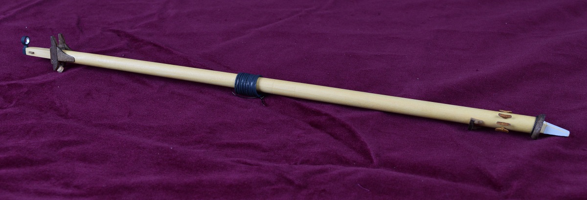 And also the Gaff. The Gaff is what attaches to the top of the mainsail, and would be raised and lowered with the sail. 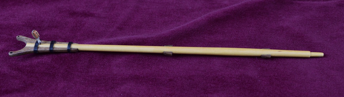 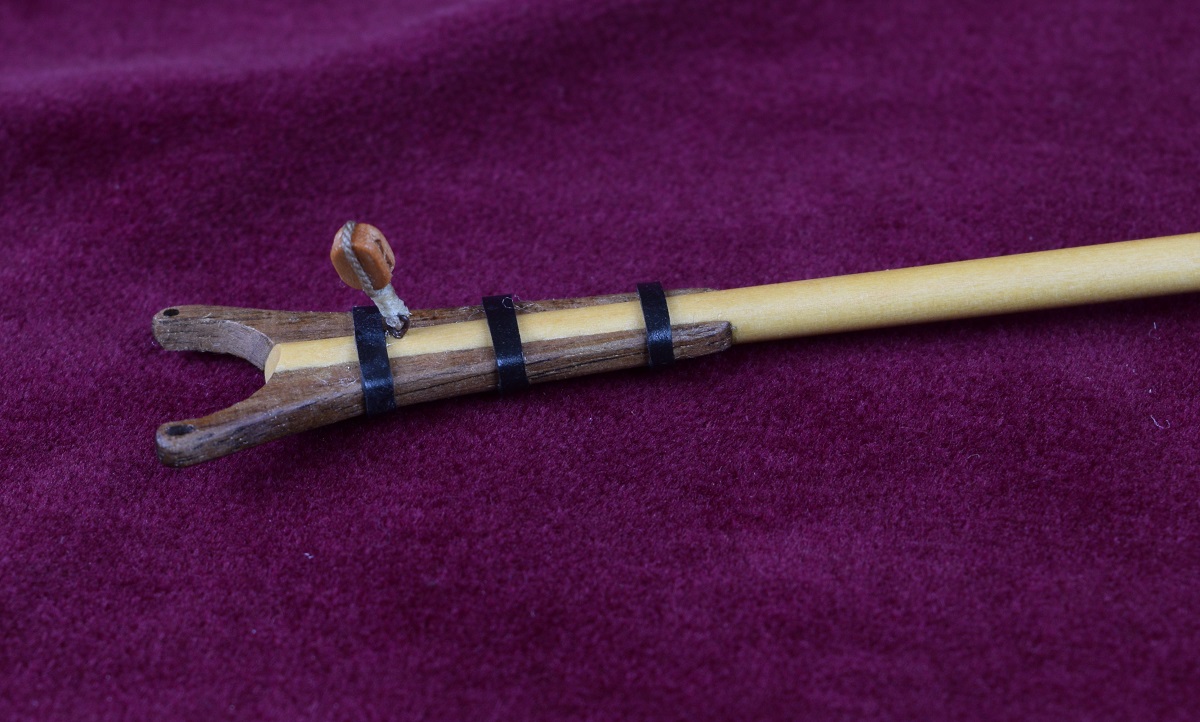 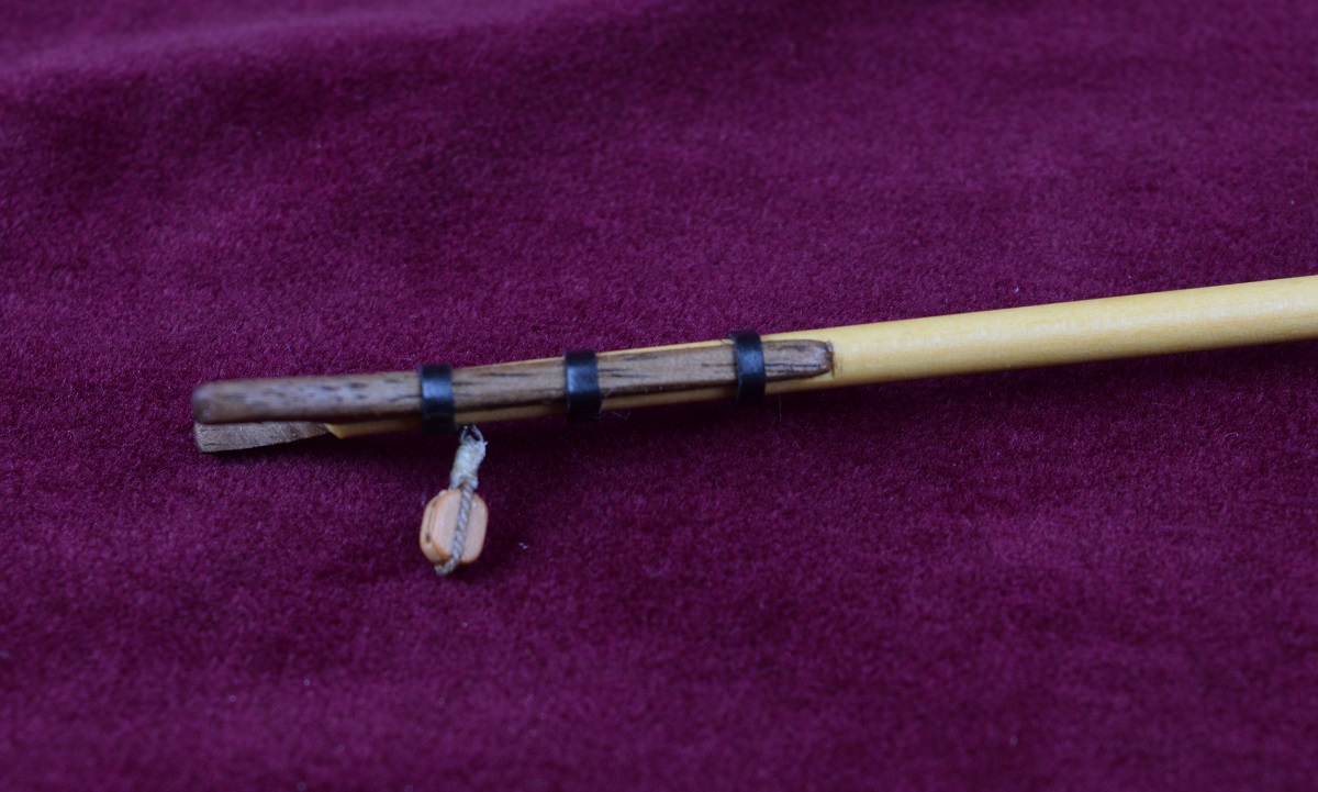 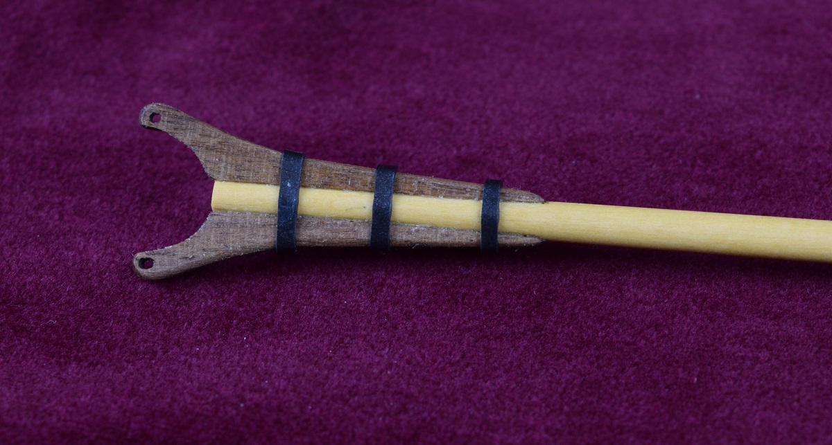 I've got the Main boom shaped, with a working sheave installed instead of the 'hole' the instructions say to use, the jaws mounted and strapped. Tomorrow I'll get the chocks and cleats installed and hopefully get both the yards made and fitted out, and then I'll be ready to start rigging!
|
|
#
?
Nov 20, 2020 20:54
|
|
|
I know you're done, but did you ever make scale humans to put on this model? It'd be cool to have the thing fully rigged with dudes hanging in the shrouds and ratlines and manning the swivel guns and whatnot. What was the crew complement on one of these, anyway?
|
|
#
?
Nov 20, 2020 21:00
|
|
|
babyeatingpsychopath posted:I know you're done, but did you ever make scale humans to put on this model? It'd be cool to have the thing fully rigged with dudes hanging in the shrouds and ratlines and manning the swivel guns and whatnot. I did not. I wanted to try to find at least one dude to put next to the ship for scale, but discovered that there was pretty much nothing in the age of sail type people available in 1/48 scale. I think there are a bunch now, but I've never gotten any. Honestly not sure on the crew complement. Figure 4 guys to a gun with 4 to a side and you have 16 guys for the main battery, probably at least another 8 for the swivels. Then you have to sail the ship and that's probably 12'ish guys. My wild rear end guess would be around 45-50 but I could be way off. Keeping in mind that this isn't really a ocean crossing ship, it's a small sloop that would have been used as a privateer, so they would be mostly doing coastal duty or at most a couple days away from land so could theoretically be a lot heavier crewed in order to man prize vessels that they managed to take. The concept of this type of ship would be that it's got enough armament and crew to take down unarmed or lightly armed merchantmen, but fast enough to get away from anything that resembled a real naval vessel. A big square rigger like a frigate would be able to run her down when sailing downwind, but the sloop rig could point a lot higher into the wind in order to get away from any square rigger.
|
|
#
?
Nov 20, 2020 22:08
|
|
|
Finished up all the masting! I still need to attach one side of the parrels to the gaff and boom, but I'll just call that part of rigging. The main boom with sheave. 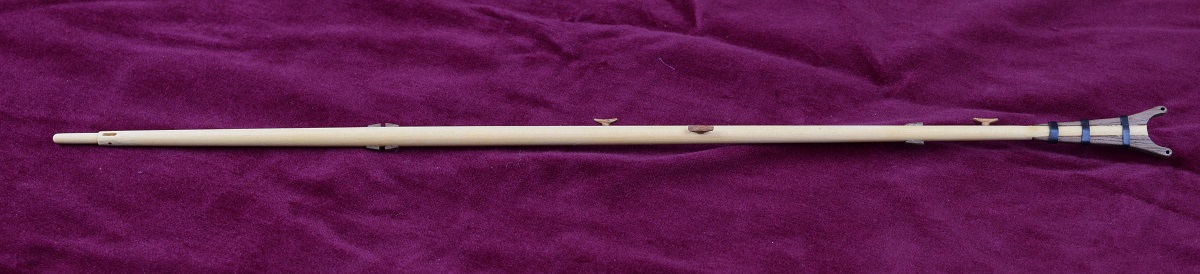 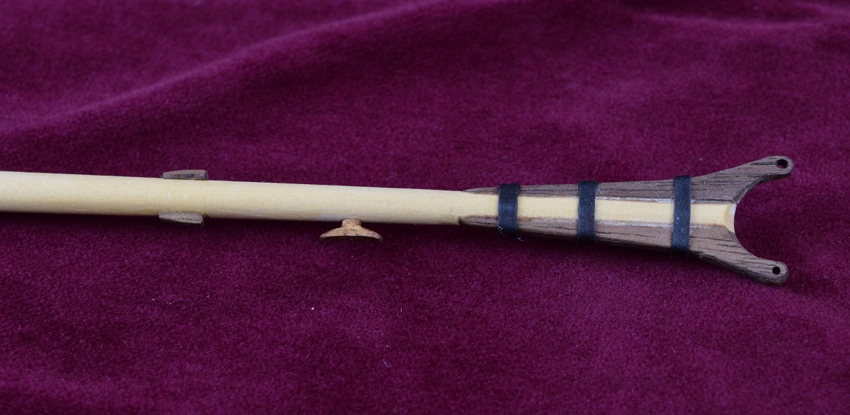 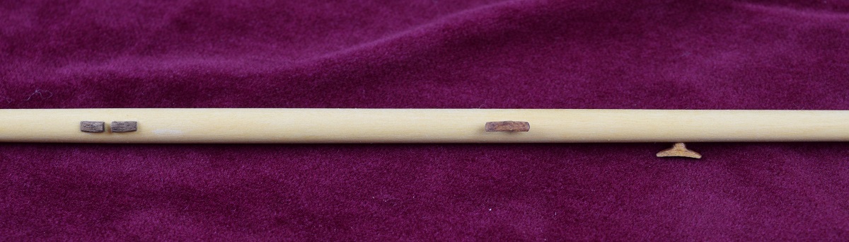 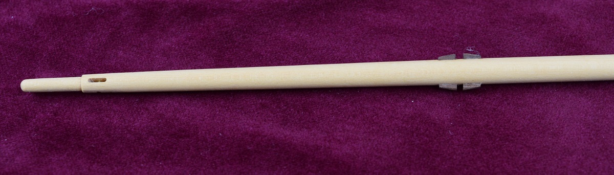 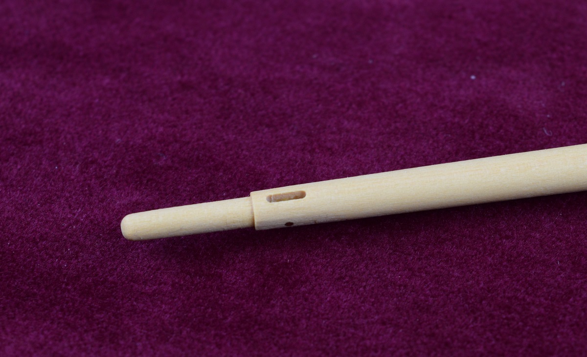 The topsail yard and spreader yard. I did have a do-over on the topsail yard when I cut too deeply into it after I was all but finished. Oops. Oh well, only 1 do-over for all the masting (not counting the multiple bowsprits I made prior to switching to boxwood), I'll call that a win! Note: Yards are the big wood bits that are horizontal on square rig sailing ships to hold all those sails up. This specific ship has a single square rigged top-sail, so it has 2 yards, one above and one below the top-sail. The top yard would be lowered to the bottom yard when this sail was furled. 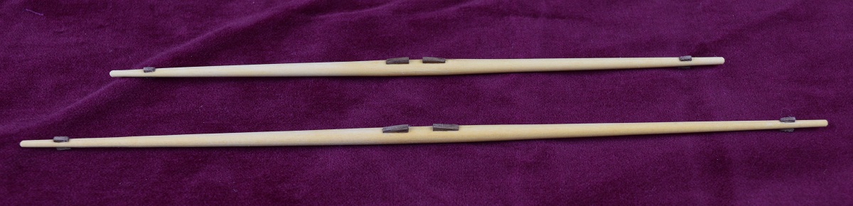 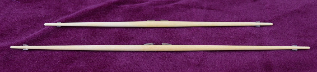 And everything all lined up together ready to start getting rigging. The mast hoops are 'captive' in that there is no way to remove them as they are solid cast metal rings on this model. Top to bottom in the photo: Topsail yard. Spreader yard. Gaff boom Main boom Top Mast Main Mast Jib Boom Bowsprit 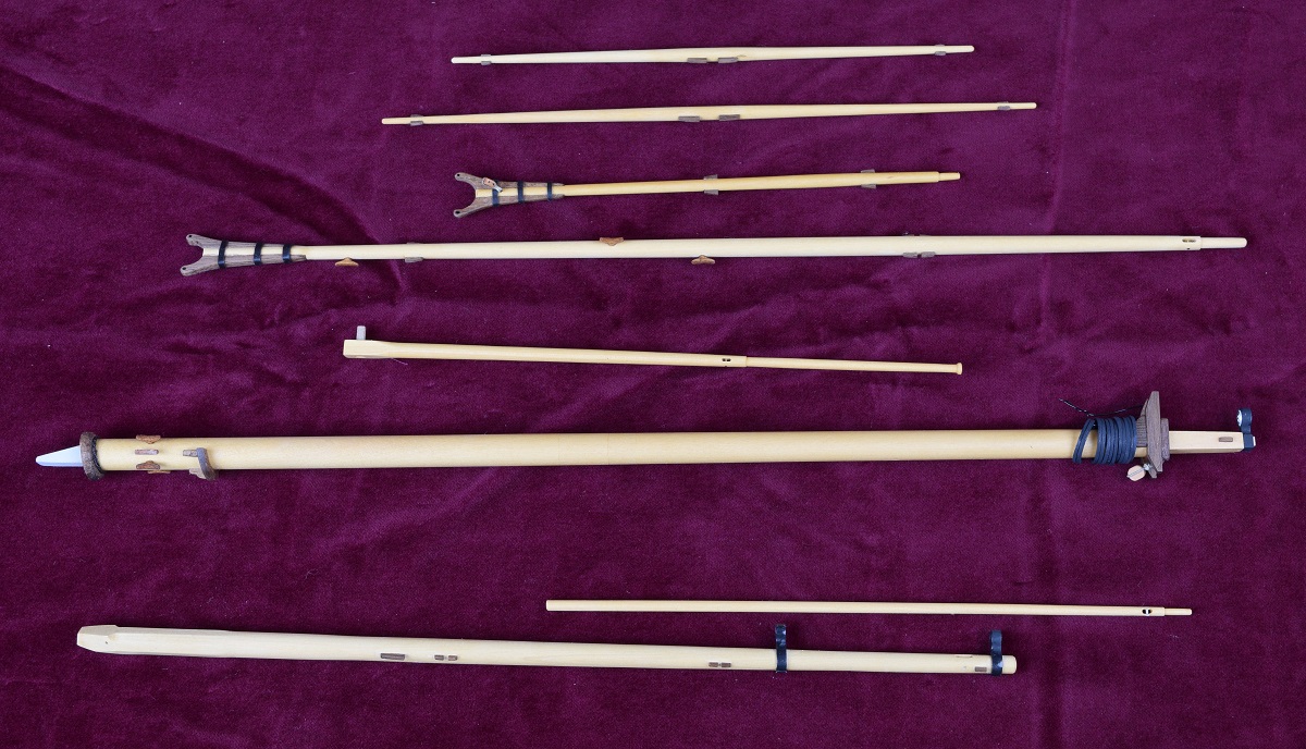
|
|
#
?
Nov 21, 2020 20:49
|
|
|

|
| # ? Apr 26, 2024 05:35 |
|
|
Not super happy with how the swivel gun mounts looked, so I built a 'U' shaped one to compare them.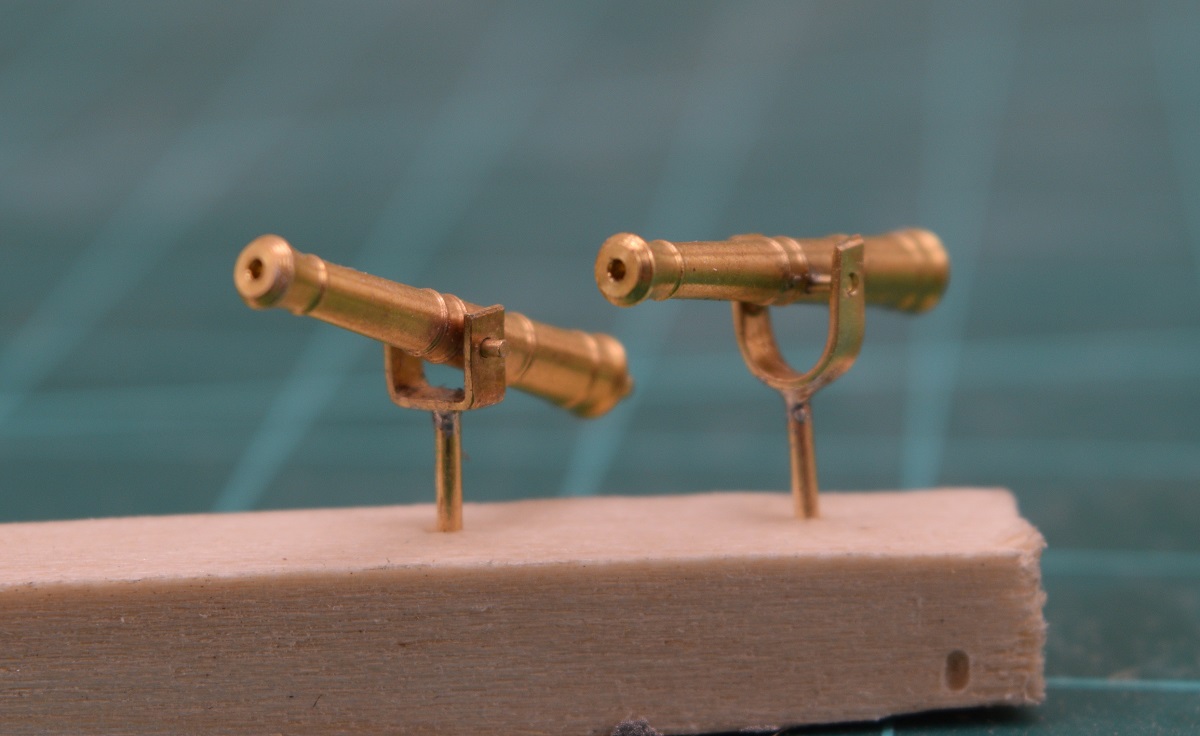 I decided that I liked the U shape better, but that the gun needed to sit lower in the yoke, similar to the square one. So when it came to making the yokes for the swivel guns, one of the biggest challenges to my thinking, would be how to drill the holes through the soft brass evenly so that the trunions would be level, and consistent. Secondary issue, making the 'U' shape consistently the same size. After messing with a few different techniques I decided that really the only satisfactory solution was some sort of a jig, so I started playing with wood to make something, and what I eventually landed on was this solution which used some of the left over bits from the boxwood I used for the masting. I used the boxwood instead of scrap basswood because of it's hardness. Step 1 (no photo, just a terrible paint drawing) was to mark the depth and width of the "U" shaped hole that I wanted as the outside edge of the jig former on the end of a piece of boxwood. I then found a cutting bit for the mill that was the right width, and placed the wood flat on the mill floor in the vise, and simply ran the mill into the wood creating a 'slot' on one edge of the wood, with a natural "U" shape due to the round nature of the cutting bit. Here is a paint drawing illustrating what I mean, as seen looking down on the cut. 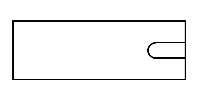 I then took a smaller piece of boxwood (again, scrap that was cut off after shaping the masts) and milled the end to a rectangular shape that would barely fit inside of the above slot, filing it so that it was the exact same thickness, and then sanding enough to allow for the brass strap to fit along both sides at the same time. I then used a file and filed the inside of the "U" shape into this piece. Finally, I glued another piece of boxwood on top of the slot I'd cut into the first piece. Bam, jig! 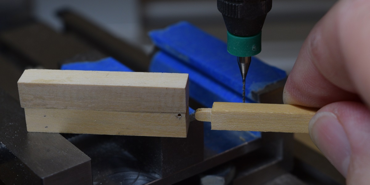 I laid the jig on it's side and clamped it into the mill vise. The "T" on the insert piece is so that I would have the same side 'up' on every use for consistency. 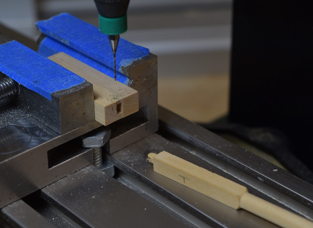 Using a small pair of the pliers with the round ends for making rings, I formed a small "U" in the brass strap, made sure it was as perfectly even as possible, and then stuck the "U" into the jig. 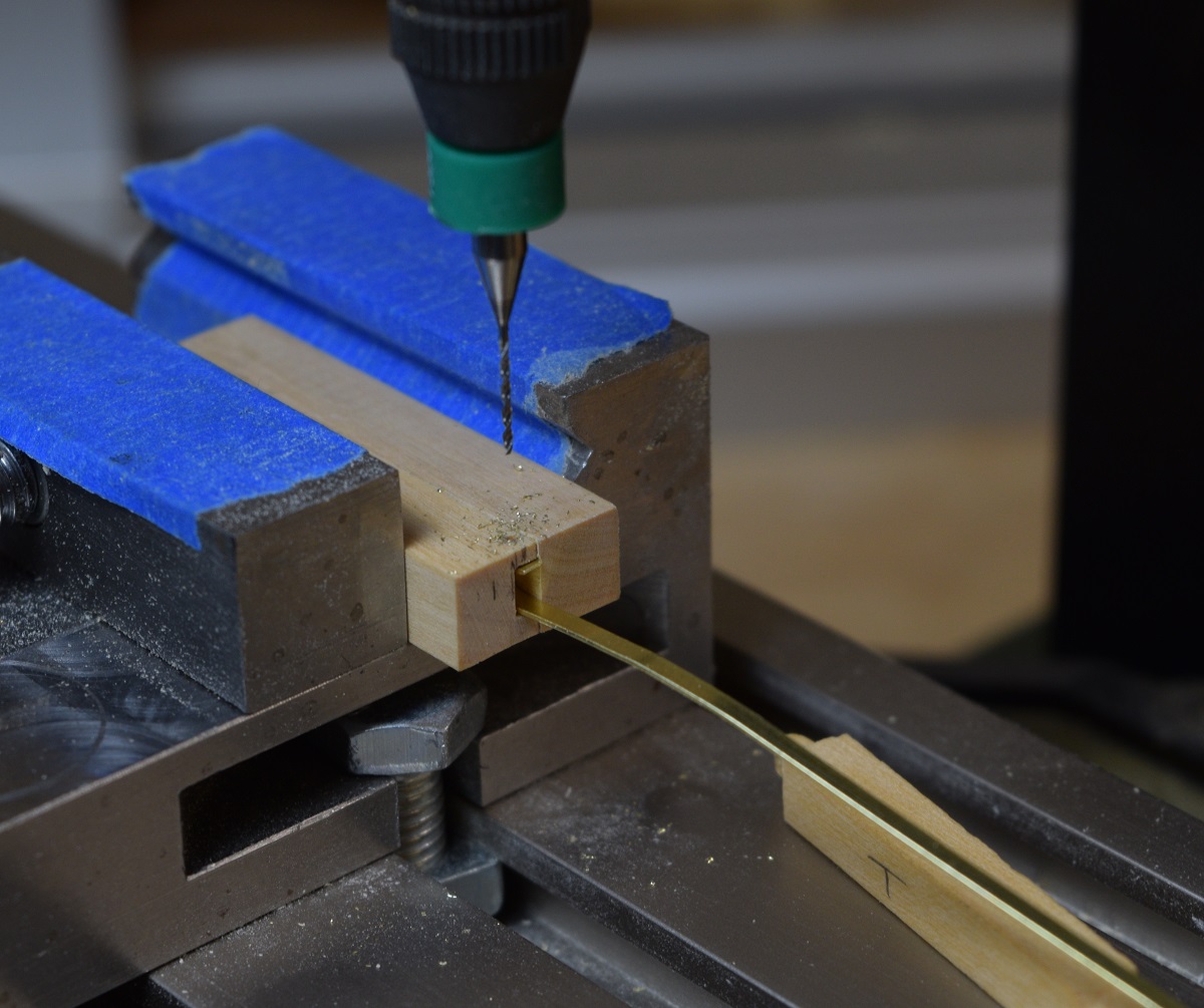 The insert piece is then pushed firmly into the jig inside of the brass "U" to force it to shape. 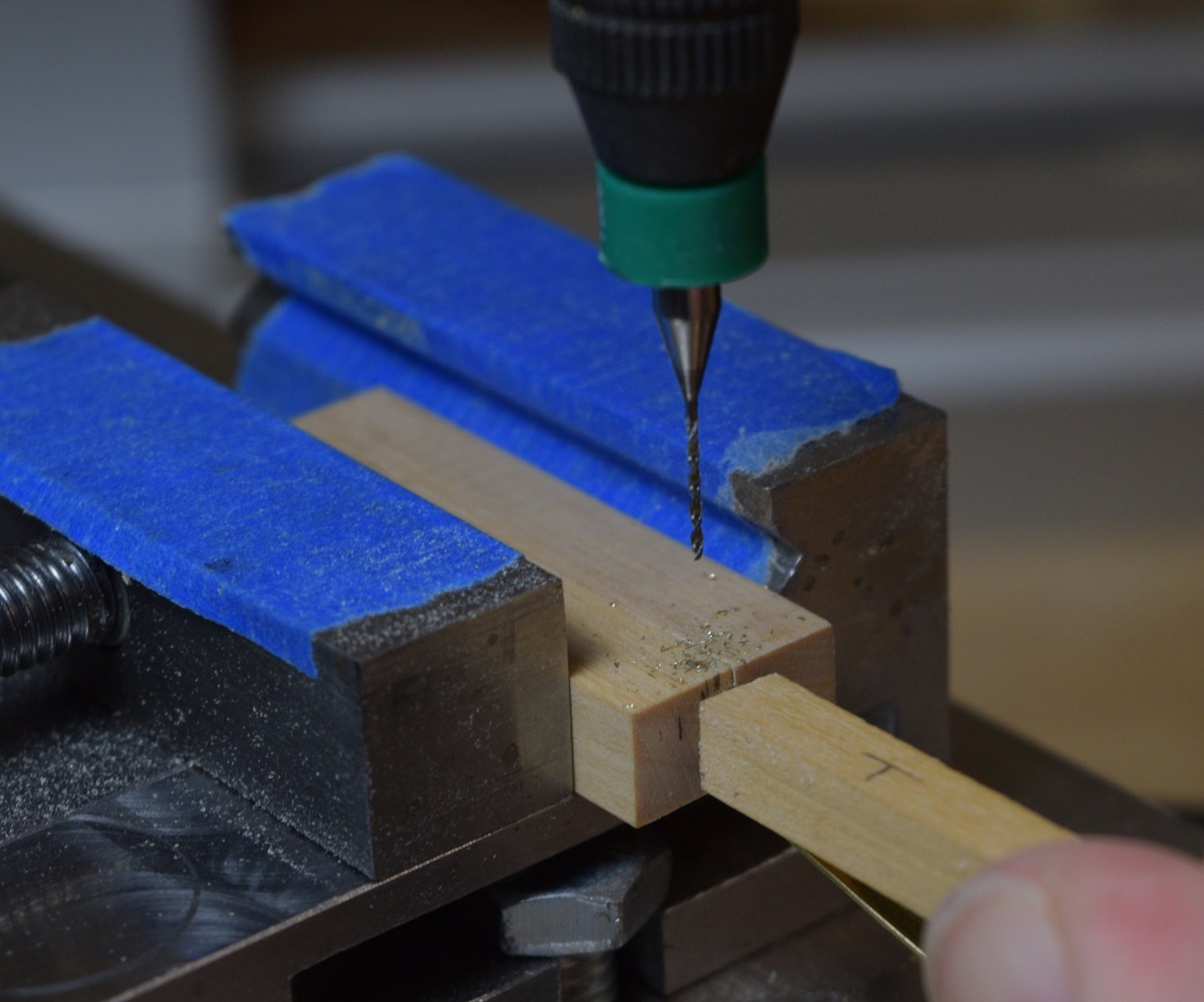 The mill head was positioned to drill into the center of the brass strip, and while holding the insert firmly, run through the jig and the brass. This was the touchy part, as if I moved the insert I could have easily snapped the drill, and I only have one bit this size. Need to get some more, I use this size a lot (#74). 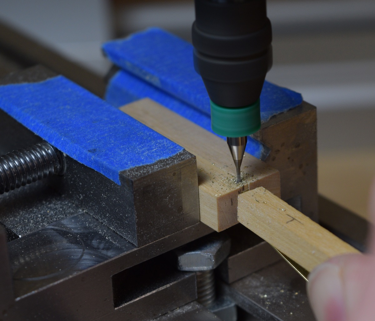 Remove the insert, which usually pulls the brass strip out with it. When it doesn't, just pull it out with the long end 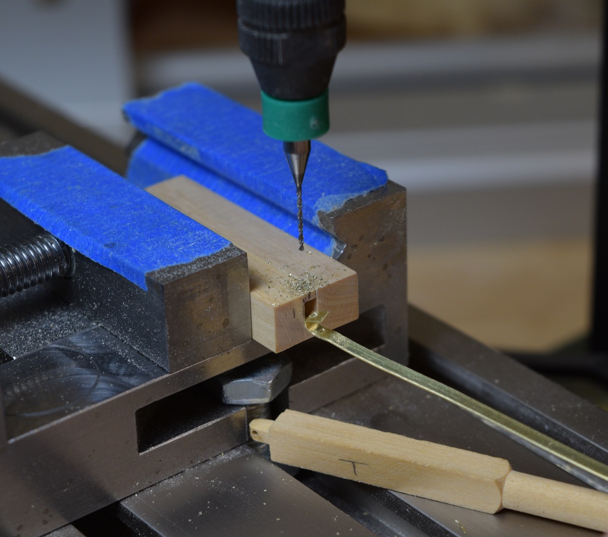 All that's left after that is to trim the ends with a Xuron precision end cutter, and solder it to the base rod. I have to remake one of them because somehow the hole on one side is way off. It must have slipped in the jig, no idea how, but I'll just call it practice, and the jig is still clamped in the mill, so not a huge deal. 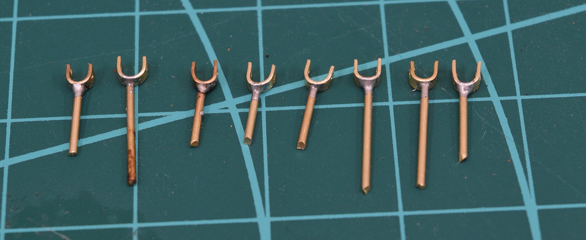 After finishing up all the swivel gun yokes, I took yet another side-trip and started building a base to hold the ship when it's done. I started with just the two supporting timbers on the end like the photo, and eventually decided to just use one more in the center to keep the visibility of the hull open as much as possible. A real shipyard would have a lot more supports I'm sure. 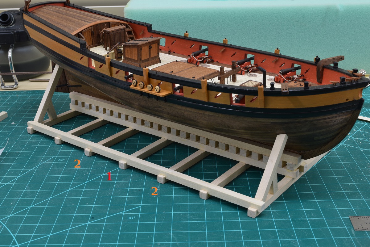 Back to the swivel guns, after making the yokes, it was time to solder on the handles. 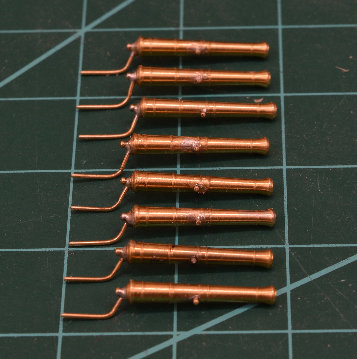 Next I soldered the base rods onto the yokes. This was a pretty good imitation of the keystone cops, as I kept getting the handles too hot and making them fall off, followed by doing the same to the yoke rods when re-attaching the handles. In the future I'm going to invest in some different silver solders that melt at different temps. You do the first joint with high-temp, next one with medium, and the last (if you need three) with low temp solder. They also make some heat-sink compounds that you can place between joints to help keep the one cool. 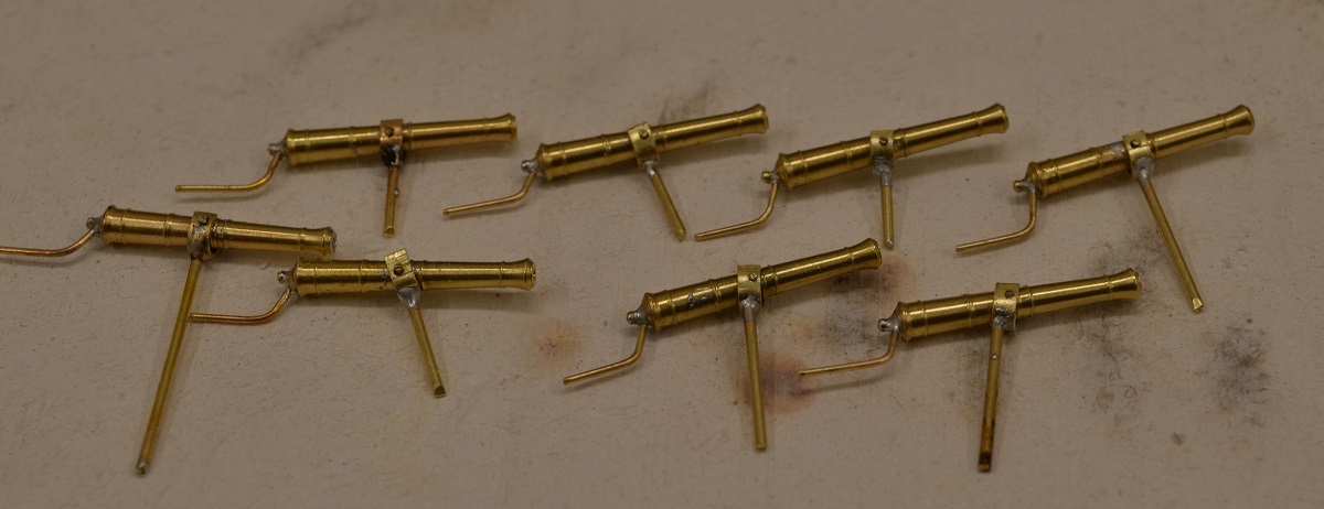 After filing/cleanup, stuck them on the ship for the pictures. 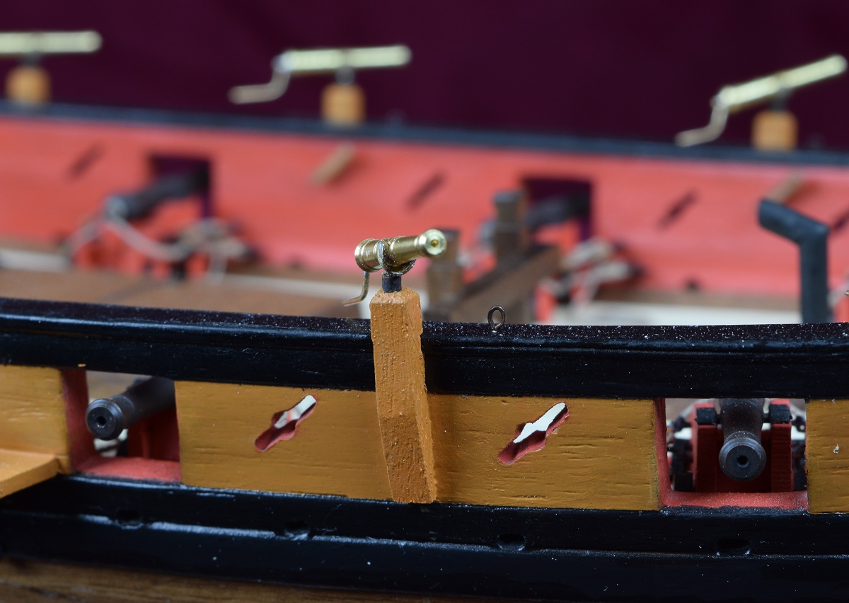 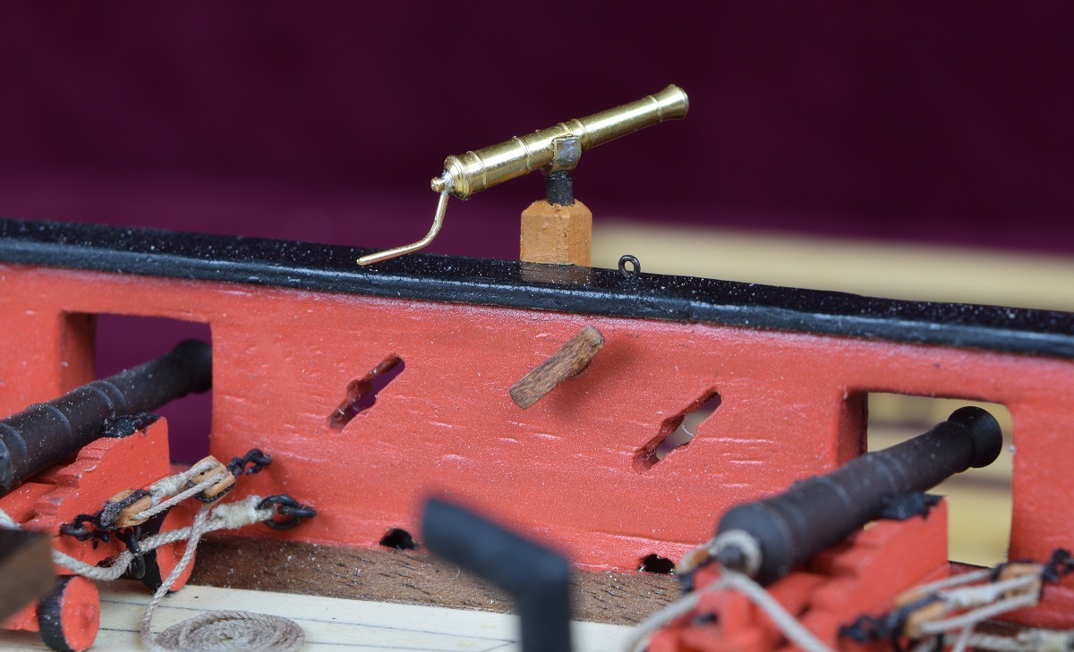 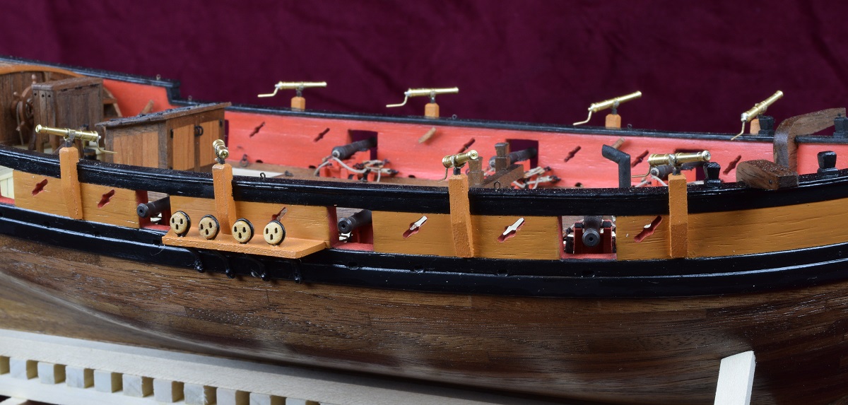 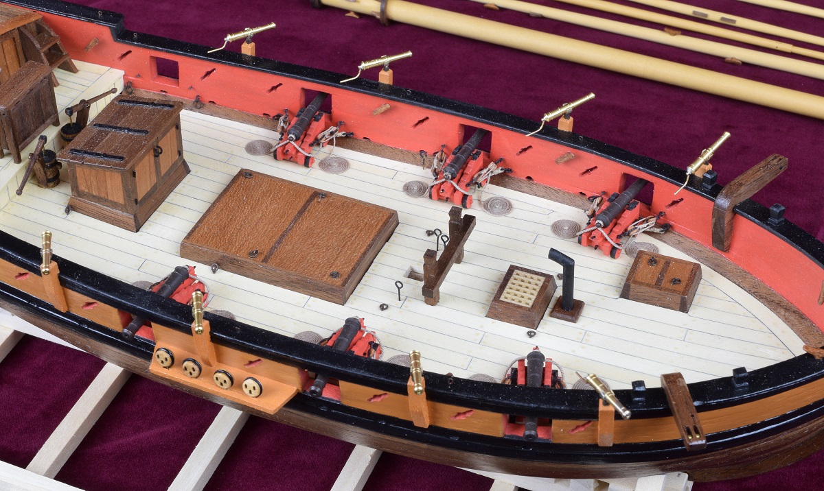 These will be blackened, and a knob added to the handle end. Obviously they are just dropped into their mounting tubes at this point and are not secured, or that would be pretty interesting! Going to try JAX chemicals Pewter Black (and brass cleaner) since it should also blacken the solder, whereas the Birchwood Casey Brass Black leaves the solder a gorgeous silver. Thanks to a friend for letting me try his chemicals!
|
|
#
?
Nov 22, 2020 01:59
|
|