


|
Thanks for making this thread it is much needed! I occasionally mess around in Fusion and it's relatively easy, but I definitely still draft faster by hand. Is Revit pretty much just architecture or would it be useful for someone drawing furniture/cabinets?
|
 #
¿
Mar 18, 2021 14:30
#
¿
Mar 18, 2021 14:30
|
|


|

|
| # ¿ Apr 26, 2024 22:45 |
|
|
This is a 'what program should I use I only want to learn one' question, but basically, which one of these danged things should I invest the time and money into? I run a very small (like me and sometimes another guy) woodworking business and have always done my drafting by hand but I need to get on the CAD bandwagon because I know eventually I'm going to need to get on the CNC bandwagon. I mostly do furniture, a lot of turned/lathe stuff, a lot of it is more curved/carved, not just cabinet boxes. I would like something that can make decent looking renderings to show clients, as well as normal dimensioned 3 view drawings and can also spit out a parts/cut list. I would also like it to not cost thousands of dollars. I also don't want to invest a bunch of time learning XYZ and then have it die in 5 years or whatever. I've messed about a bit with the free Fusion360 and it sort of mostly does what I need? It is not so great at generating cut lists or anything like that unless I remember to label and dimension every single part in the drawing. I could grumpily afford to pay for an actual license if most of the problems people have with it are with the personal use license. I was all excited about Solidworks until I read the last page of this thread and it seems like maybe that's not such a great route. Would Rhino do what I need, or is it going to be really clunky when I just need to draw some square cabinet boxes? I've played with Blender a bit and it was fun and relatively intuitive, but I didn't think it would translate well to 'dimensioned drawings.' What the heck is Revit?
|
|
#
¿
Aug 19, 2021 22:47
|
|
|
Is 'tell me how much force it will take to make this table tip-over' a think the simulations in Fusion 360 can do? I've gotten handy enough with it that I bought the paid subscription for work, but I keep getting some error whenever I try to solve the simulation I've created. It's something dumb with the program not installing Nastran that I'm sure is solvable, but after about 5 clean installs it still won't try to solve the simulation and I'd love to know if what I'm trying to do will even work.
|
|
#
¿
Aug 26, 2021 02:10
|
|
|
Thanks for the info. I haven't done any physics since high school AP physics uh....15 years ago? Here's an end-on drawing of the table and base:  The table will weigh like 250lb all told, the center of mass is 18.75" up from the bottom along the centerline. How much downward force at one edge would it take to lift the opposite edge of the base? Basically, how many pounds of someone using the edge of the table to stand up/lean on is going to make it move and feel unsteady? Is there a generic formula/equation for this, or some way to run it in a simulation? By the calculation someone mentions here: https://www.eng-tips.com/viewthread.cfm?qid=154454 I get a horizontal force of ~90lb tipping the table over, which is useful, but doesn't give a great picture of what force it will take to knock all the glasses on the table over. I'm gonna cross post this in the stupid questions thread I guess?
|
|
#
¿
Aug 26, 2021 18:29
|
|
|
oXDemosthenesXo posted:This iss almost exactly a question that I was asked in an interview almost 10 years ago and got wrong lol. Still got the job at least and it made me much more aware of how important fundamentals are. E: I just realized probably none of that matters because your drawing is only for half the table and whatever weight is out near the edge of the table on the side of your drawing is balanced by an equal amount of tabletop on the other side of the table and I guess that�s why COG works out and we can forget all that other stuff, lol E2: As a follow up question out of curiosity, would the height of the COG matter if the force were being applied horizontally at the edge of the table? Like if someone were trying to shove it over? Kaiser Schnitzel fucked around with this message at 21:21 on Aug 26, 2021 |
|
#
¿
Aug 26, 2021 21:17
|
|

|
Thanks that makes sense. Fulcrum is all that matters to get it moving, COG is what determines where it tips over once it starts moving. Please feel free to make a basics of engineering thread, lol. You explain all this really well!
|
|
#
¿
Aug 26, 2021 21:48
|
|
|
Does FreeCAD do modelling and stuff too? For some reason I thought it was 2d only.
|
|
#
¿
Sep 17, 2021 18:29
|
|
|
biracial bear for uncut posted:I mean, they have a website bragging about the features they have. Yeah sorry I should have googled first, posted later.
|
|
#
¿
Sep 17, 2021 18:32
|
|
|
Has anyone found a good youtube or something that explains what the differences between components/bodies/etc. are to someone very new to 3d modelling? Same for what 'good' workflow looks like? Or if there is a good little tutorial thing I've missed somewhere? I can draw stuff sort of okay in Fusion and I've watch lots of youtubes but I mostly just bump around in the program until I find a button that does the thing I need and I know the way I'm doing it is not at all the best way.
|
|
#
¿
Sep 20, 2021 18:06
|
|
|
I'm a bit frustrated in Fusion, probably because I'm a dummy. I'm trying to draw a workbench, and am having some problems with components and I think the browser. Here's the thing: I've got 5 boards, which are all copies (made with the 'Move' tool) of the first board. I would like the two vertical boards to be named 'Apron Boards,' but when I change their name, it changes the name of all of them. Is there any way to make a clean copy of a component that isn't still connected back to the component it is a duplicate of? Like can I just copy it somehow to gently caress around with and not have it change other ones? Similarly, is there a way to move things up a level in the directory? If I go to the body a component is made of, click that and try to make a new component, it is always nested under the original component the body belonged to, which isn't what I want. I want new, clean, unencumbered components that I can make into whole different assemblies! I think I should not be using components for every single board and just use bodies instead, and have the top, the aprons, legs whatever be components made up of multiple bodies representing boards. The reason I have made them all components is that I would like to use the 'Parts List' tool to generate a cut list-as far as I know that's the only way to get fusion to spit out something like a cut list and it only looks at components, not bodies. Because of that, I'm making each board it's own component labelled with it's dimensions. Is there a better way to do this? Is there a good 'you're a dummy that is just now colliding with fusion/3d modelling, START HERE' youtube series or soemthing? NYC CNC is great but there stuff seems more focused on CAM which is still a ways away for me, and thye don't seem to have a basics playlist. They do offer a paid program on their website-anyone ever tried that?
|
|
#
¿
Oct 14, 2021 01:49
|
|
|
Yooper posted:You can copy a component and then "Paste New". It will then be independent. biracial bear for uncut posted:Why do they need a separate name if they're all the same size piece of lumber? Just name it "(Width) by (Height) by (Length) Lumber" and use the balloon and bill of material tools to keep track of what is what and where you use it. honda whisperer posted:
|
|
#
¿
Oct 14, 2021 13:45
|
|

|
^^That's cool as heck I love your posts^^ Does anyone know if there is a way to make Fusion 360 export 'Component Name' in one cell and the dimensions under 'Bounding Box' from the component properties into separate cells in excel for all components at once? That would sure make generating cut/parts lists a ton easier instead of having to name each component with it's dimensions (which may change as the design changes). It looks like there is a plugin/app thing called Bommer that may do this, anyone tried it?
|
|
#
¿
Oct 30, 2021 20:36
|
|
|
Is there any way to sculpt components after you've modelled them in Fusion? I am drawing a chair and it has alot of rounded curves that don't quite fit with a normal fillet or swept profile and I'm trying to see if there is anyway to model them. Basically, how do I model this:  From this: 
|
|
#
¿
Dec 12, 2021 20:25
|
|
|
 Can folks itt please talk about CAD stuff and not other posters and just generally try to be excellent to each other. 
|
|
#
¿
Jan 10, 2022 20:05
|
|
|
If I already have a decent handle on Fusion360, is there any reason to learn sketchup? Does it do anything fusion doesn't do?
|
|
#
¿
Jan 23, 2022 21:10
|
|
|
NewFatMike posted:No please for the love of God do not use SketchUp. It creates non manifold models. If you�re planning on doing architectural stuff, then maybe.
|
|
#
¿
Jan 23, 2022 21:45
|
|
|
NewFatMike posted:Are you doing nesting work against the 4x8 or building actual cabinetry in Fusion with joints and such? Building actual cabinetry designs out with joints etc. I'm not aware of any plug in that will take those parts and try to nest/optimize them onto a sheet of plywood. I'd love something that will just generate a reliable cutlist without me having to put all the dimensions in the part name, tbh.
|
|
#
¿
Jan 24, 2022 00:05
|
|
|
Yooper posted:Practical Machinist is the worst forum ever. Makes GBS look functional. They have a really small and slow but interesting and polite woodworking forum that I like to read occasionally, but it is all extremely boomer, if very skilled and knowledgeable boomer.
|
|
#
¿
Mar 17, 2022 17:42
|
|
|
Since we�re on the topic of 4x8 CNC routers-anyone have experience with AvidCNC�s stuff? All the woodworking YouTube content creators seem to have them and love them which always makes me suspicious.
|
|
#
¿
Mar 18, 2022 20:43
|
|
|
If you cant get a grid or anything, at least throw a tape measure or ruler or something on there. That helps a ton with being able to sort out the distortion.
|
|
#
¿
Apr 15, 2022 23:04
|
|
|
some kinda jackal posted:Hey hole wizards, I continually forget where the cool kids talk about Fusion 360 so hopefully this isn�t too far off base. If you use the fillet tool on an inside corner in will make a concave fillet. You might try that and see if you can make it big enough to cover the whole thing. Otherwise make a sketch of half the cross section and then Revolve that around the central vertical axis. Or model a sphere and use that as a tool via the combine command to remove the concave are of your part.
|
|
#
¿
Jun 6, 2022 17:18
|
|


|
some kinda jackal posted:I simplified the example but in my ideal scenario the �hole� isn�t in the centre, which I probably should have mentioned, so revolving would be more difficult. I did pick up on the inside edge fillet thing after you mentioned it, and got exactly what I needed by doing a primary perimeter sketch, extruding it up the thickness of my base, offsetting the exterior and extruding that up the total height I needed, then filleting the joining internal edge. I probably butchered the terminology but thanks for putting me on the right path. If in future you wanted to do something similar and needed to do it as a revolve because it was a more complex shape, you can make an axis wherever you need it. There are several options under the 'Contruction' menu.
|
|
#
¿
Jun 6, 2022 17:49
|
|
|
meowmeowmeowmeow posted:Does fusion have a sweep tool? That's usually the best way to run a certain profile along a certain path. Yes it does, and that would probably work too. I've only messed around with sweeps a few times and am still not exactly sure what the 'right' way to use it is. I've had some problems orienting the profile in the right direction and I'm not sure what I'm doing wrong.
|
|
#
¿
Jun 8, 2022 17:06
|
|
|
DC to Daylight posted:I don't have too much experience with Fusion, but for most problems I've had with sweeps, the root cause was the path not being perpendicular to the cross section at the point of intersection, so you end up extruding some funky projection of what you intended. This is exactly the problem I�ve usually had. I wish I could make a single sketch of whatever profile and then sweep it along multiple edges. I would like for example to draw an roundover profile and sweep it along all four edges of a tabletop, but I�ve struggled with being able to do that and wind up redrawing the profile on each edge and funny things sometimes happen in the corners where the two profiles should meet.
|
|
#
¿
Jun 8, 2022 20:22
|
|
|
After a whole lot of false starts, I finally figured out how to do spiral reeding in fusion: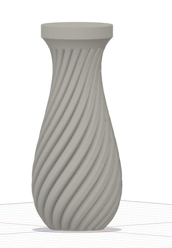 It's a real awkward and clunky workaround since fusion doesn't have an easy way to make a helical plane, but I learned some knew tricks and found out about this whole new tab I'd never touched before called 'surfaces'
|
|
#
¿
Jun 21, 2022 18:29
|
|
|
His Divine Shadow posted:Making an end grain cutting board, it's one component made up of lots of bodies. I basically made one piece of the board, then used a rectangular pattern to make the rest. Fusion made them all look like the cross section of a single tree, which was weird looking. For the appearance part, I think applying an appearance to component applies to the bodies as if they are all one thing, whereas applying the appearance to an assembly applies it to each component individually. If you right click on the component/body and select 'Texture Map Controls' that will let you move things around to get different looking grain. The unfinished 3d/solid wood materials usually look the best as far as showing grain orientation imo. Kaiser Schnitzel fucked around with this message at 21:49 on Nov 19, 2022 |
|
#
¿
Nov 19, 2022 21:42
|
|

|
I am sure solidworks is vastly superior in some way, but for my little business fusion for $450/yr sure seems like a deal.
|
|
#
¿
Dec 4, 2022 18:38
|
|
|
Yeah just have like Back Wall as a component >activate that �Back Wall� component>create new component �Stud�>make pattern using �Stud� component, and it will make every stud in the pattern it�s own new component. �Back Wall� will now a be an assembly or w/e the term is (symbol will change to three little blocks in the tree). If you want to get really organized, instead of using the �stud� component to make the pattern, make a stud component in the �stud� component and use that to make the pattern out of. Then you have an assembly called �Studs� that has all the studs in it and you can collapse that in the tree easily. Similarly, make an assembly for �wall sheathing� or whatever, and then it�s really easy to show/hide things or change materials as a group. As far as I can tell you can have sub-assemblies of of sub-assemblies ad Infinitum E: I can�t remember specifics, but there may be times when you don�t want to use the pattern command. I think if you modify the original that everything is patterned off of, it will change all of them? I think it depends on where the changes happen in the timeline. Sometimes Move/Copy > Paste New is better when you want a copy of something but plan to modify one or the other. Kaiser Schnitzel fucked around with this message at 16:34 on Dec 7, 2022 |
|
#
¿
Dec 7, 2022 16:31
|
|
|
Anyone used Shapr3D? A friend has been messing around with it and said it�s super easy and intuitive compared with his limited Solidworks experience.
|
|
#
¿
Jan 9, 2023 16:37
|
|
|
oXDemosthenesXo posted:What does a license for Fusion cost these days? I caved last week and got a 1 year solidworks hobby license because I keep finding reasons to use it. At least this way I only have to have the ~~3DEXPERIENCE~~ once a year. My professional/small business license is like $4-500/yr? I can't remember off the top of my head. It's not cheap, but it's not terrible and its way more affordable than SOLIDWORKS. I have to say the drawings space is not what I use the most, but it is the part that makes my life easiest, even though it's one of the clunkier parts of F360.
|
|
#
¿
Jan 14, 2023 20:08
|
|
|
My mechanic still keeps all his customer records on some ancient DOS program
|
|
#
¿
Mar 10, 2023 22:23
|
|
|
Anyone have a recommendation for a LiDAR scanning app for iPhone? Preferably one that easily exports something Fusion can use
|
|
#
¿
Mar 23, 2023 21:21
|
|
|
NewFatMike posted:What are you intending to do with it? E: this is what I can get into fusion, it just thinks that whole thing is 1/4" wide instead of like 12" wide  e2: I guess as a workaround I can take screenshots of the model and import/scale them and use them as canvases behind my sketches Kaiser Schnitzel fucked around with this message at 23:17 on Mar 23, 2023 |
|
#
¿
Mar 23, 2023 22:44
|
|
|
honda whisperer posted:That scan looks great and scaling it should get you where you want to go. e: duh, the button that says 'scale mesh' e2: thanks for the help I think I got it figured out. Somehow I need to make this broken mesh into a body so I can project it into sketches I guess? Kaiser Schnitzel fucked around with this message at 02:24 on Mar 24, 2023 |
|
#
¿
Mar 24, 2023 02:09
|
|


|
In Fusion is there a way to repeat what you just did, including all the settings? For instance, I made a sketch of an elevation of some cabinets, and then need to extrude all the pieces back 16," with each piece being its own component. Selecting them all and extruding them as 'New Component' will sometimes work, but it well let two adjoining pieces Join into one body. Instead I right-click, Repeat Extrude, and have to select 'New Component' and type in the distance every time. Is there a way so that when I right-click, Repeat Extrude for it to be pre-populated with whatever my last extrude settings were?
|
|
#
¿
Jul 13, 2023 03:00
|
|
|
What�s the advantage of OnShape over Fusion? Costs 3x as much for a commercial license and seems much less fully featured. No rendering in the basic ($1500/yr) license and no CAM either. Are there more features at the free level than free Fusion? Isn�t a lot of folks� big complaint about Fusion that it stores everything in the cloud and hates if you try to work offline (but you still can) where it sounds like Onshape is totally cloud/browser based and won�t do anything without internet? I don�t do real machining or fancy product design, but Fusion has so far done most everything I need it to (and I know is capable of a lot more). It isn�t cheap for a small business, but I do feel paying for the full set of features has been worth it, whereas if it was priced like onshape it wouldn�t be worth the money for me.
|
|
#
¿
Jul 14, 2023 04:09
|
|
|
Thanks for all the info. I guess because generating drawings was one of the main things I needed CAD for, I upgraded to a paid subscription fairly quickly so all the Autodesk drama didn't affect me much, though I do remember hearing about it. And I can't be too mad about my very powerful FREE software becoming slightly less useful when it's still free. They moved to a web-based log-in system for F360 recently and I was kind of grumpy about that but then it turns out it's actually maybe better since chrome will store my password and that's been about the extent of my Autodesk fuckery experience. I won't say the AutoDesk training stuff has been fantastic, but there is a ton of youtube etc. content for it. My buddy was trying to teach himself SW and bounced off it because there wasn't nearly as much free training stuff out there. I guess if you can afford SW, you can also afford to send someone for professional training or they learned it in engineering school or w/e. I didn't think I would really use the renderings workspace in Fusion that much, but it's actually something I've wound up using quite a bit to show things to clients and the 3d materials work really well with that. Surprising to me that for 3x the price OnShape doesn't have that feature when it seems to my not-computer brain it shouldn't be that hard to do. What makes anyone think OnShape won't also start to roll back free features? They gotta make money too. I remember SW making it harder to get a free education version or loving with their free/cheap offering recently too. E4C85D38 posted:I really want to like OnShape, but I spend a bunch of time without connectivity, and even "check in constantly but work offline to sync later" is a huge step up. E: NewFatMike posted:That�s a massive bummer � I�ve been meaning to but I�ll try to prioritize Alibre CAD for a nice nodelocked software to test out this summer. Inshallah it�s good! Kaiser Schnitzel fucked around with this message at 16:37 on Jul 14, 2023 |
|
#
¿
Jul 14, 2023 16:35
|
|
|
I'm feeling really dumb in Fusion and I think something must have changed in the latest update. In sketches, my fractional inches always used to round to 32nds or 64ths and I feel like I could control that as a preference somehow, but now suddenly it is going all the way down to 256ths or 128ths if applicable and my brain just doesn't think in those units. I can still make it round to whatever unit in the drawings interface, but not in sketches. My unit settings: 
|
|
#
¿
Jul 31, 2023 19:34
|
|
|
Yooper posted:
|
|
#
¿
Jul 31, 2023 20:30
|
|

|

|
| # ¿ Apr 26, 2024 22:45 |
|
|
Spaghett posted:It's pretty sick that you use a flattened, crumpled piece of paper as a monitor
|
|
#
¿
Aug 1, 2023 01:49
|
|