


|
Jaded Burnout posted:I've been assuming that by "lamp" they meant "light fixture" Good point.
|
 #
?
Jun 29, 2019 18:12
#
?
Jun 29, 2019 18:12
|
|


|

|
| # ? Jun 10, 2024 05:26 |
|
|
Can I assume you are in Germany? That cable shouldn't be smaller than 1,5mm�.quote:Folgende Richtwerte m�ssen bei der Elektroinstallation eingehalten werden � ACHTUNG auf Leitungsl�nge: So your Dunstabzugshaube won't be a problem.
|
|
#
?
Jun 29, 2019 23:55
|
|

|
RabbitWizard posted:Can I assume you are in Germany? That cable shouldn't be smaller than 1,5mm�. Thank you, I was worried that the wall / wire / light fixture situation was too different in the US to get useful answers, but now I'm feeling pretty good about it. Sorry for confusing the others
|
|
#
?
Jun 30, 2019 06:39
|
|

|
Hello sparkies, I have been utterly baffled by something and I figured you might be able to help out: I have a bathroom with a vanity light and a vent fan/light that the PO in my house had done. The way the switch is set up is shown here:  Note that it is not set up for a common feed. I tested this circuit on a common feed switch and when I did, throwing one switch (I believe at the time it was the top but I tried a few combinations) turns on both the vent fan/light and the vanity light, even when the other hot is disconnected. In its current configuration, the one it was in when I found it, the top switch turns on the vanity, but the vent fan/ceiling light will only turn on if the top and bottoms switch are on. This is where it gets intriguing:  Either orange connection turns on the newer light (including if you twist the white and black together with the brown), and only blue turns on the vent fan/light. Which seems to imply that for the old wiring the black is the neutral and the brown is a shared hot. I can't seem to figure out how this circuit was originally wired but did they used to use a brown/orangish color for hots and black as neutral back in the 50s? I am now kicking myself for not having a common feed tab still attached doubting that the brown wire was in fact the hot. Edit: I bridged the feeds and put the brown wire on that side, then connected the two orange connections to one neutral and the blue connection to the other neutral. This time either switch turned on both lights. Blindeye fucked around with this message at 00:47 on Jul 1, 2019 |
|
#
?
Jul 1, 2019 00:10
|
|


|
pidan posted:Thank you, I was worried that the wall / wire / light fixture situation was too different in the US to get useful answers, but now I'm feeling pretty good about it. Well, you can do a lot of things then. Easiest would be to fix an Aufputzsteckdose with 2 D�bels. Depends on how willing you are to cut a piece out of the R�ckwand of your Schrank. But an Aufputzsteckdose is legit, so no problems there. Even if it is behind stuff. Second solution, take a pick and a hammer and make space for a Unterputzdose without damaging the cable. It'll be as good as the other one, but may fit behind your Aufh�ngeschranks without damaging the R�ckseite. Betonier it in to pass inspection.
|
|
#
?
Jul 1, 2019 00:36
|
|
|
RabbitWizard posted:Well, you can do a lot of things then. Easiest would be to fix an Aufputzsteckdose with 2 D�bels. Depends on how willing you are to cut a piece out of the R�ckwand of your Schrank. You're making this up aren't you E: wait, I want the US sparkies to try and translate based on context alone
|
|
#
?
Jul 1, 2019 00:44
|
|

|
Hubis posted:You're making this up aren't you But I love your Vorverurteilungspraktizismus before you even know me.
|
|
#
?
Jul 1, 2019 01:00
|
|
|
Blindeye posted:Hello sparkies, I have been utterly baffled by something and I figured you might be able to help out: The brown is your hot, the lone black is the switch leg for your old light, and the white/black combo are both the leg for your new light. Why they are both connected is beyond me, but disconnecting that light and seeing how they are connected to it might shed some light. None of them should be a neutral though, and if one is, it shouldn't be hooked up to your switch. My fix: It sounds like you've already disconnected the tab between the two hot posts on your switch? If so, split your hot (brown) with a pigtail, and hook it up to both of your hot posts. Then hook the lone black up to one leg post, the other black wire to the other leg post, and then cap the white wire, as it kind of shouldn't be needed unless I'm wildly misinterpreting something. A lot of these guesses could be confirmed with a multimeter or voltage detector. Slugworth fucked around with this message at 01:19 on Jul 1, 2019 |
|
#
?
Jul 1, 2019 01:13
|
|

|
RabbitWizard posted:Well, you can do a lot of things then. Easiest would be to fix an Aufputzsteckdose with 2 Dübels. Depends on how willing you are to cut a piece out of the Rückwand of your Schrank. I work in many german-built cabinets for a german owned company and am shamed that all I can get out of that is something about an outer connector and some specific but unknown type of wall shame on an IGA fucked around with this message at 01:23 on Jul 1, 2019 |
|
#
?
Jul 1, 2019 01:21
|
|

|
That said, DIN color code supremacy is no lie
|
|
#
?
Jul 1, 2019 01:27
|
|
|
Slugworth posted:My guess: So that was my thinking, but it doesn't explain why brown-new light's white NM wire with nothing else connected turns on the new light with both black's disconnected. It also doesn't explain that when I created the pigtail split of the brown, it meant either switch could turn on both lights. I'm baffled.
|
|
#
?
Jul 1, 2019 01:28
|
|
|
Aufputzsteckdose: Unterputzdose:  Unterputzsteckdose: (from behind)  Putz = The stuff you put on the outer wall. In this case, the level you are going for. Aufputz (Up-Putz) = You attach the socket to the wall. Unterputz (Under-Putz) = You make a hole in the wall to fit the socket.
|
|
#
?
Jul 1, 2019 01:29
|
|
|
Blindeye posted:So that was my thinking, but it doesn't explain why brown-new light's white NM wire with nothing else connected turns on the new light with both black's disconnected. It also doesn't explain that when I created the pigtail split of the brown, it meant either switch could turn on both lights.
|
|
#
?
Jul 1, 2019 01:39
|
|
|
Slugworth posted:Your test involved having the white and black on the same post, right? Try it again with that white disconnected. I'm not an electrician, so I'm firmly into "some sort of weird shared neutral type situation thing?" territory, but that's my guess. That white is tied into a bunch of neutrals, and you're energizing that whole bundle of neutrals, which is why both lights turn on. I don't know, in this theory, why that would turn things on rather than just shorting, but..... shrug. Give it a shot. I tried both White+Black+Brown = one light on as well as White+Brown and Black+Brown which did the same. Brown and old black switch leg turned on the other light. Yet with a pigtail both switches turned on both lights. You're right that in that one I had white and black tied, but that was because I had tested it and it turned on the one light. I might just throw in the towel for now and say it's good enough and work on some projects where success may be more likely.
|
|
#
?
Jul 1, 2019 02:15
|
|
|
Blindeye posted:Hello sparkies, I have been utterly baffled by something and I figured you might be able to help out: Get a circuit tester and find out which wire is the source hot. You'll save yourself a lot of time. The little $5 one with 2 probes and a bulb will work fine. You can use a multimeter set to AC volts instead if you got one.
|
|
#
?
Jul 1, 2019 07:18
|
|
|
kid sinister posted:Get a circuit tester and find out which wire is the source hot. You'll save yourself a lot of time. The little $5 one with 2 probes and a bulb will work fine. You can use a multimeter set to AC volts instead if you got one. Well that is what I did already...hence my mention that I believe the brown must be the hot. The lines I drew in the second picture all carry 120v across my circuit tester. It's the fact that setting it up for a common feed doesn't work that has me scratching my head.
|
|
#
?
Jul 1, 2019 14:08
|
|
|
Blindeye posted:Well that is what I did already...hence my mention that I believe the brown must be the hot. The lines I drew in the second picture all carry 120v across my circuit tester. This is sounding like some sort of bizarre miswired switch leg. Find the source hot and we'll get this straightened out. Turn the power off, take down your vanity light and the cover off of the light/fan combo. Which one has 2 runs of NM into it?
|
|
#
?
Jul 1, 2019 16:24
|
|
|
kid sinister posted:This is sounding like some sort of bizarre miswired switch leg. Find the source hot and we'll get this straightened out. Turn the power off, take down your vanity light and the cover off of the light/fan combo. Which one has 2 runs of NM into it? I would but it's tiled all the way up the wall so I am *not* making plans to gently caress with the light mounting anytime soon. I might make a trip to my attic crawlspace for the vent fan when I replace it but right now it requires a ladder and tolerating 110 degree heat sooooo....
|
|
#
?
Jul 1, 2019 18:12
|
|
|
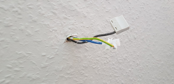
I'm going to take a moment to bitch about UK wiring colours. Blue is neutral. Fine, whatever. Ignore that. Then we have one brown wire, and one bright yellow/green "look at me!" stripy wire. The brown is earth, right? Because it's the colour of earth? And the vivid poisonous frog coloured one is the dangerous live wire, right? Nope. Other way round. Why? Well they started with red/black for live/neutral. Sounds good. Red is bad, black is neutral. Then they added a green earth. Alright, so far so making sense. Then they added a yellow stripe to the green earth. Why? Dunno, can't find a reference. But OK it's now drawing some attention but at least live is still red. Well motherfuckers say goodbye to your black and red I guess because they're hard to distinguish under certain lights and with certain colour blindness, let's go with some muted versions, blue and brown. gently caress. Bonus: blue, previously used as a phase colour, is now the colour for neutral. Black, which was previously used for neutral, now indicates a phase. 
|
|
#
?
Jul 1, 2019 19:36
|
|


|
Please tell me the color changes are at least obvious enough to tell which version you are working on - like if it's the new colors you have green with a yellow stripe on the ground and would never have that in the old version. It's still insane, but that would be at least less insane. Of course knife crime island is still using ring mains, right?
|
|
#
?
Jul 1, 2019 19:53
|
|

|
Motronic posted:Please tell me the color changes are at least obvious enough to tell which version you are working on - like if it's the new colors you have green with a yellow stripe on the ground and would never have that in the old version. That may be why they added the yellow stripe. I guess for colorblind people it might be hard to tell the green wire from a red or brown one.
|
|
#
?
Jul 1, 2019 20:00
|
|
|
Motronic posted:Please tell me the color changes are at least obvious enough to tell which version you are working on - like if it's the new colors you have green with a yellow stripe on the ground and would never have that in the old version.  Motronic posted:Of course knife crime island is still using ring mains, right? 
|
|
#
?
Jul 1, 2019 21:02
|
|
|
That blue/black switch was horribly thought out.
|
|
#
?
Jul 1, 2019 21:05
|
|
|
Yeah, if you're going to change your coding the last thing you want to do is re-use one of the legacy colors for something different in the new system.
|
|
#
?
Jul 1, 2019 21:13
|
|

|
I guess you just need to know "there's no red in here so the thing I think might be a neutral will probably kill me." Not like I don't use a non-contact voltage tester all the time anyway, but it just seems like that switch is setting up for accidents for DECADES into the future.
|
|
#
?
Jul 1, 2019 21:25
|
|
|
kid sinister posted:This is sounding like some sort of bizarre miswired switch leg. Find the source hot and we'll get this straightened out. Turn the power off, take down your vanity light and the cover off of the light/fan combo. Which one has 2 runs of NM into it? Okay, I finally figured it out; I made a mistake on my labeling and realized that I was right that yes, the brown was hot, and yes, the white was one light's switch leg. What I didn't correctly note is that both black wires are switch legs for the other light. I capped off the older wire so I could make the most of the newer NM and that did the trick. Not sure why twisting the white and black and circuit testing worked to turn on one light before, but then again I was losing my mind yesterday. Sadly, the old box is not grounded, sometime in the future I'll be heading into the attic crawlspace to take care of that myself.
|
|
#
?
Jul 2, 2019 01:21
|
|
|
Blindeye posted:Okay, I finally figured it out; I made a mistake on my labeling and realized that I was right that yes, the brown was hot, and yes, the white was one light's switch leg. What I didn't correctly note is that both black wires are switch legs for the other light. I capped off the older wire so I could make the most of the newer NM and that did the trick. Did you try the ground wire from that 1950s NM? Ground wires first appeared in the 50s in bathrooms. Them and kitchen countertops were the first places to require grounding.
|
|
#
?
Jul 2, 2019 03:51
|
|
|
kid sinister posted:Did you try the ground wire from that 1950s NM? Ground wires first appeared in the 50s in bathrooms. Them and kitchen countertops were the first places to require grounding. The remaining 1953 NM has no grounds in it. That new piece of NM they added has a ground wire but it's not grounded. There's two circuits left in the house for the bedrooms that use them for lighting and a few outlets I restored to 2 prong until I know what to do long term (I need to make my own trip to the attic crawlspace. The electrician that did my panel says that one of the two circuits does end up in a junction box tied into a grounded modern NM so I could replace those lines if I did some fishing, but the other circuit has no ground all the way to the box: it powers the doorbell, a single hallway light, and a single two-prong outlet. The downside is the larger of the two circuits mostly uses exterior walls that were treated with closed-cell foam insulation at some point in the past and I'd hate to create long voids fishing in the new line.
|
|
#
?
Jul 2, 2019 04:27
|
|
|
Blindeye posted:The remaining 1953 NM has no grounds in it. 
|
|
#
?
Jul 2, 2019 05:55
|
|
|
I am pretty sure that was a mod done by the electrician that installed the new light; the similar NM wire elsewhere in the house does not have a ground running parallel, but a handful of old boxes were grounded by adding a copper wire later and tying it to a junction box with modern NM going to the panel. That wire is actually screwed to the box in the back, I think. Edit: now I am doubting myself. I have a few samples of the old NM and it had no grounding wire but maybe that one is? Jesus Christ. Blindeye fucked around with this message at 15:53 on Jul 2, 2019 |
|
#
?
Jul 2, 2019 15:20
|
|
|
Blindeye posted:That wire is actually screwed to the box in the back, I think. That's how it was done at the time. Your switches and outlets get grounded by being attached to the box, not by actually tying into that ground wire. It works....eh. I use wagos to grab those types of short grounds and make a pigtail in the box so things can be tied to ground according to current code.
|
|
#
?
Jul 2, 2019 16:24
|
|
|
Motronic posted:That's how it was done at the time. Your switches and outlets get grounded by being attached to the box, not by actually tying into that ground wire. Oh I know. I just am not sure when it was done. I did a top to bottom replacement of every single outlet in my house. 1 outlet is on an original nm circuit with no ground, and 5 outlets are on the other original circuit without grounds. A few other outlets use original NM but have grounded boxes. My attempts to take apart the old NM to find a ground were unsuccessful.
|
|
#
?
Jul 2, 2019 18:18
|
|
|
Blindeye posted:I am pretty sure that was a mod done by the electrician that installed the new light; the similar NM wire elsewhere in the house does not have a ground running parallel, but a handful of old boxes were grounded by adding a copper wire later and tying it to a junction box with modern NM going to the panel. It is. They used to ground the boxes in the old days. They'd poke the ground wire back out the entrance and attach it to one of the gang screws on the outside. Technically it's still legal, but it's not good practice because it's hard to verify visually once the walls are finished. Like I said, kitchens and bathrooms were the first rooms to require grounding. It's very possible for only those rooms to have it while the rest of the house doesn't. I've also seen those rooms at the beginnings of branch circuits have ground wires, then not use ground wires for everything further down the branch.
|
|
#
?
Jul 2, 2019 18:25
|
|
|
The fluorescent light in my kitchen just seems to have died but I don't have spare bulbs or a multi-meter at home and I'd like to get it back on ASAP tomorrow. It's got 4 T8 tubes-could one of them failing have caused the whole fixture to quit? I put it in about 5 years ago- could the ballast be dead? I guess I've never really done much electrical troubleshooting, what's the best place to start? My plan was new bulbs then check the switch with multi-meter, then check the fixture with multi-meter. Are there T8 replacement LED's I should be looking at instead?
|
|
#
?
Jul 9, 2019 02:47
|
|

|
There are some LED replacements. Some of them are drop ins, some require you to bypass the ballast completely so they just get straight 120vac
|
|
#
?
Jul 9, 2019 03:07
|
|


|
Costco has T8 LED tubes that are drop-in replacements for fluorescent tubes in an existing fixture. I use them to light my workshop and am pretty happy with them.
|
|
#
?
Jul 9, 2019 03:19
|
|

|
A magnetic ballast (which is most likely what failed) will cost about $10 if you want to do it cheap or if you'll replace the fixture in the next few years.
|
|
#
?
Jul 9, 2019 04:04
|
|

|
I replaced a finicky light switch in the bedroom and swapped the fan/light switch positions in the bathroom the other day without electrocuting myself  Now, if any of these folks on FB Marketplace can sell me their used ceiling fans, I can have a go at installing those in the small bedrooms. While I'm up there, I figure I might as well have a go at resolving another issue, and I'd like some input on that. My attic access has a few runs of wiring running right across it, very nearly taut. It makes removing and replacing the ceiling panel a pain in the rear end, as well as moving bulky items into and out of the attic space. I know the "best" way of resolving this would be to do entirely new runs between the panel and the endpoints, but would it not be easier to install a couple junction boxes and splice in the extra wire in between those boxes needed to move these runs away from the attic access?
|
|
#
?
Jul 9, 2019 12:31
|
|
|
Beach Bum posted:I replaced a finicky light switch in the bedroom and swapped the fan/light switch positions in the bathroom the other day without electrocuting myself J-boxes and 20ft of matching wire is a perfect solution to your problem. You can even cram a couple of runs into a single box since you don't need room for devices. It's neater and about a dollar more to run them separately depending on the number of wires here.
|
|
#
?
Jul 9, 2019 15:29
|
|

|

|
| # ? Jun 10, 2024 05:26 |
|
|
Kaiser Schnitzel posted:The fluorescent light in my kitchen just seems to have died but I don't have spare bulbs or a multi-meter at home and I'd like to get it back on ASAP tomorrow. It's got 4 T8 tubes-could one of them failing have caused the whole fixture to quit? I put it in about 5 years ago- could the ballast be dead? I guess I've never really done much electrical troubleshooting, what's the best place to start? My plan was new bulbs then check the switch with multi-meter, then check the fixture with multi-meter. Sounds like a dead ballast. It happens. The test is to try the tubes in another known working fixture. If they work there, then it's a dead ballast. If this is a 4 foot fixture with 4 tubes, get a 4xF32T8 ballast at any hardware store. Get a package of the tiny wire nuts too, the blue or orange colored ones. Turn the power off and cut out the red, blue and yellow wires near the ballast and strip them. Untwist the black and white wires from the ones feeding the fixture. Remove the old ballast and put up the new one. Match wire colors, twist and cap them. Before you put the cover back on, turn the power back on and see if it does. If so, turn the power off again, bundle up the wires and replace the cover. Yes you can get LED T8 replacements, but the direct drop in replacements require a working ballast. Some require you bypassing the ballast which would work in your situation.
|
|
#
?
Jul 9, 2019 18:11
|
|