


|
UserNotFound posted:Actually, what you should look into is to is use a 555 timer to blink the lights very quickly. 99% of LED lights do this to save power. You could also use pulse width modulation to vary the intensity if you wanted. I don't know how useful it would be for a bike headlight, but hey, it's there if you want it! v  v v
|
 #
?
Apr 2, 2008 14:31
#
?
Apr 2, 2008 14:31
|
|


|

|
| # ? Apr 27, 2024 03:25 |
|
|
UserNotFound posted:But a bicycle is the perfect place for a heatsink: lots of air movement! quote:Also, maybe I didn't read your orignal post well enough, but you could put 2 LEDs in series for a 6.4V drop, which would halve the power wasted by the resistors and be closer in efficiency to a switching supply? quote:Actually, what you should look into is to is use a 555 timer to blink the lights very quickly. 99% of LED lights do this to save power. That said, I do have a 556 in my parts box....
|
|
#
?
Apr 2, 2008 16:16
|
|

|
Are you looking to drive the LED's with the 555? I know they can source up to 200mA, so it seems like that would not be enough.
|
|
#
?
Apr 2, 2008 17:19
|
|

 RIVALS!!!!!
|
Mach Won posted:Are you looking to drive the LED's with the 555? I know they can source up to 200mA, so it seems like that would not be enough. There's no way I'd try to source all the current through a 555. However a 555 has plenty of power to drive a FET. Which would be used to switch the LEDs. Not that I'm going to go that path.
|
|
#
?
Apr 2, 2008 20:14
|
|
|
Rather than trying to put together a switcher, have you thought about just buying a power module? Something like this: http://search.digikey.com/scripts/DkSearch/dksus.dll?Detail?name=296-20400-ND It's a switcher with all the support circuitry already on the board. You just need to add a few discretes (cap and a couple voltage setting resistors) and you're good to go. If you go to TI's page you can probably get one as a free sample.
|
|
#
?
Apr 2, 2008 21:57
|
|

|
Hillridge posted:Rather than trying to put together a switcher, have you thought about just buying a power module? Something like this:*snip* That's a neat little power supply. But it won't handle more than a 5v input. So I'd still need something to step the voltage down to 5v. And they're $11.50 each. Check out the part I linked to earlier. The LM2576 is a neat little chip. I bought sets to build 10 of them, for $23.50 shipped. I just need to add two caps. For a total component count of five.
|
|
#
?
Apr 2, 2008 22:12
|
|
|
Well your light is certainly well thought out, and I eagerly await pictures and stories of your night rides. A night race in a cemetery with the cops showing up is probably the most exciting thing I've ever done 
|
|
#
?
Apr 3, 2008 19:29
|
|
|
Okay, I've just gone through this thread, and I've got a couple of possibly stupid questions. I'm getting into doing PIC programming, the PIC 16F628A in particular, and I'm making one of those silly POV toys - the kind that you swing around, and it displays a message. I've got the programming basically done - I'm running 8 RGB LEDs, and the way I'm storing the data takes 3 bytes per 8-pixel column. No problem there. So, the first question: I see reference to "ICSP" for programming PICs, does anyone have experience with this? I see references to "schottky" diodes, and I have no idea what those are. I've got some "rectifier" diodes, but haven't a clue if they're the same thing (I assume not) Second - I want to run this thing off a 9V battery, but of course the circuit only wants 5V. I assume there's a simple way to drop to about 5V with a voltage regulator, right? One of the future projects that I want to build is a wall-mounted, rotary POV device that is computer controlled via serial (or USB - the PIC 18F4550 series looks great!) - I just have to figure out a good way of transferring data and power to a spinning platform.
|
|
#
?
Apr 4, 2008 05:08
|
|

|
TwystNeko posted:Okay, I've just gone through this thread, and I've got a couple of possibly stupid questions. In-circuit serial programming allows you to program your target circuit without taking the microcontroller itself out of the circuit. You'll need an ICSP compatible programmer (such as a PICKit2), a PIC (duh), and some resistors. Take a look at this picture:  This picture in particular refers to the PICKit2 programmer, but the basics apply to all the Microchip ICSP programmers. You connect the two ICSP pins directlyto the proper device pins, and you connect the VPP pin from the programmer to the ~MCLR pin. You also connect the programmer to your circuit's Vdd/vss. The extra circuitry is necessary for two reasons: to hold ~MCLR high during normal use (it's an active low reset) and to isolate the programmer from your Vdd/vss. During programming, the programmer drives ~MCLR to +12V so the diode prevents the programmer from adversely affecting your power supply. As you can see from the picture, you can also use a 470 ohm resistor instead of a schottky diode. For all my PIC projects I've used a resistor in this capacity and it's worked fine. You could try it with the normal diode--schottky diodes are essentially normal diodes with faster switching times as far as I know--but it might not work. Also, I suppose things might explode or something. As for your second question, I don't have much experience with using batteries to power microcontrollers so I'll let someone else answer that one. My guess is that you'd be fine depending on how much current you're drawing to power those LEDs.
|
|
#
?
Apr 4, 2008 06:46
|
|
|
The easiest way is just to use a linear regulator (like one in the LM317 family), but you have to remember that linear regulators "burn off" the extra voltage, so they will waste a lot (4/9) of the power in that battery. A switching power supply is ideal for what you want to do. They can be more than 90% efficient, they're just a little harder to design. Usually you can find an example circuit in the datasheet that will do exactly what you want. Look around Microchip's website. Chances are that they will recommend a power supply chip for whatever PIC you are using. Edit: After looking at the datasheet, this PIC has a range of 2.0-5.5V. It also has very low current draw, so you could easily run it off of a couple AA batteries, or even a 3V lithium cell. Hillridge fucked around with this message at 15:36 on Apr 4, 2008 |
|
#
?
Apr 4, 2008 15:26
|
|
|
Yaknow, the SMPS that I'm using for my headlight would be ideal for driving the PIC project as well.
|
|
#
?
Apr 4, 2008 15:35
|
|
|
Nerobro posted:So, tonight I actually got some silicon hooked up on my bicycle headlight project. I'm using a 7805 vreg to cut down the power from a 9.6v 2.3ah battery pack. I'm looking to drive 50leds at 20ma each. That butts right up against the limit of the 7805. Second, ditch the 7805. You don't need it at all. LEDs don't care about voltage, as long as it's above their forward voltage. The important thing is getting the right current, and you can do that with resistors coming off of the 9.6V pack. If it's NiMH, it will give a very constant voltage from shortly after fresh until almost dead.
|
|
#
?
Apr 4, 2008 16:04
|
|

|
Captain Cool posted:First off, fifty LEDs will get you seen, but they won't illuminate the road in front of you. If you need to light up the road, you should look into high power LEDs, like 1-3W. The 7805's have been ditched. Read up a few posts to see what i found to deal with that particular bit of nastiness. Yes, nimh has a favorable discharge curve, but from fully charged, to discharged I'm looking at a drop of nearly 2.6v. I know LED's don't care about voltage, however I did do the math on the resistors, and it ended up being really ugly. That leads to my first, and second solutions. My first idea was to stack a few LEDs to get a big-ish voltage drop, and use small resistors. So say we put two LEDs in series, that gives us a 6.4v drop. The resistor to pass 20ma of current at 10.4v would be 200ohm. At 8.4v, it would be 100ohm. So I passed on that idea. Idea number two was to use big value resistors on single LED's. Which, if I understand the 7805 properly, is effectively the same thing without active voltage regulation. I'd be looking at a 7v drop, at 20ma, per led. I'd be burning up 7 watts of power doing that. So.. SMPS it is, with smallish value resistors. With the 100ohm resistors i'm dropping 1.6-1.8 volts across the resistor, so I only need to deal with a total of 1.8w of heat. I'm using pairs of half watt resistors, so I am sitting pretty in that respect. Unless I'm completely wrong....
|
|
#
?
Apr 4, 2008 17:09
|
|
|
Hillridge posted:Edit: Well, size is part of the issue, along with weight. What I'm making is designed to be spun around. Sort of like this: http://www.youtube.com/watch?v=gklBWwGyreM - my first one is just going to be on a lanyard, but future ones will be motorized. 3 AA batteries = 4.5V, but are kind of heavy relative to a 9V battery.
|
|
#
?
Apr 4, 2008 17:57
|
|
|
Speaking of bike lighting, I just finished my Red Cree taillight project. Housing is an Altoids tin. I'd guess its putting around 70-80 lumens, but its hard to tell with red. The current-regulator has a sweet 10hz strobe function, which is good for diagnosing epilepsy in the motorists behind you.    My 3xCree headlight will be completed this weekend, I'll post pics.
|
|
#
?
Apr 4, 2008 18:13
|
|
|
You guys doing this bike stuff need to figure out how to power your LED's off of your pedaling. Then these would be cool projects.
|
|
#
?
Apr 4, 2008 18:37
|
|
|
Mach Won posted:You guys doing this bike stuff need to figure out how to power your LED's off of your pedaling. Then these would be cool projects. Been there done that. They sell some very high efficiency hub generators that produce a few watts. Strangely enough, the drag from those generators does significantly impact your riding speed.
|
|
#
?
Apr 4, 2008 18:52
|
|
|
Nerobro posted:Are you trying to say 3.2 watts of LED won't get me anywhere? quote:Yes, nimh has a favorable discharge curve, but from fully charged, to discharged I'm looking at a drop of nearly 2.6v. You could run a comparator against a voltage reference and use a relay or power mosfet to switch from fresh-battery mode to normal-battery mode when the voltage drops to 9.8v or something.
|
|
#
?
Apr 5, 2008 00:45
|
|
|
Captain Cool posted:Hm. How well do 50 20-ma LEDs work compared to one 2W LED? It seems like spreading out the power would be much worse than having fewer, brighter lights, but I don't know. quote:Okay. I would be tempted to just plan for 9.6V and run the LEDs out of spec for the first 10 minutes or whatever. Or pick LEDs with enough overhead to handle the extra power. quote:You could run a comparator against a voltage reference and use a relay or power mosfet to switch from fresh-battery mode to normal-battery mode when the voltage drops to 9.8v or something.
|
|
#
?
Apr 5, 2008 03:01
|
|
|
Thanks for the help, folks. I managed to get the ICSP working, and built my "hand-powered" POV-toy. I used a 7805 to drop the current down from the 9V battery, and it all worked first time!  Now I'm just playing with the code for the POV - I've got it down pretty well. I made an image converter that takes a .gif image, and reads an 8-pixel high strip, outputting the bytecode. One question, though - what's a good way to diffuse these LEDs? they're clear ones, and the red/green/blue segments of each LED are very noticable.
|
|
#
?
Apr 6, 2008 03:26
|
|
|
Frist off, good job Neko. As for my little power supply project; It works. I got the parts in the mail yesterday. So tonight I scrounged up reasonable value caps and soldered wires to all the parts. (I mistakenly got all SMT parts..) Hooked it up. And viola, it worked. ... though when I first set it up i was a little mystified why it wasn't working. Turns out I didn't hook up the input wire to the controller chip. Ooops. Pictures to follow. I took them.. just can't be bothered to get them off the camera or downsized, or uploaded, at the moment. However, the resistors i'm using for current limiting get a little warm. Maybe I should get the voltage adjustable version of this controller chip, and use some tiny value resistor on the LEDs Nerobro fucked around with this message at 06:38 on Apr 6, 2008 |
|
#
?
Apr 6, 2008 06:35
|
|
|
Since we're all talking about LEDs, I'll have to show you the circuit and implementation I'm working on. I'm transforming a Petzl zoom headlamp to operate three superbright LEDs off of two "C" cell batteries. To do this I've constructed a regulated boost converter. I'm going to work on the protoboard today.
|
|
#
?
Apr 6, 2008 13:56
|
|

|
Random question: I have a couple (well, one, the other one seems to be dead) piezo buzzers that seem to change their sound at different voltages. The working one goes "deedleedleeedle" at 4.5v (i.e., three C-cells) and plays "London Bridge" at ?v (9v battery with small red LED and the resistor that came with it in the circuit. Yeah, I was just randomly stringing things together*) How does it do that? It has a tiny little PCB with a resistor and a 1/4"-wide lump of black stuff on it. I'm pretty sure that whatever is under the lump of black stuff is what does the sounds, but I haven't the slightest idea what it might be. *actually I was working on a "ring bell for service" type thing so InediblePenguin can call me from the bedroom, and thinking of putting the LED in the button-handle for confirmation of annoying the crap out of me. I ended up going with just the deedleeedle and no light. Also, how do you tell which end of the resistor to start from when reading the code? None of the ones I've ripped out of various broken devices seem to have any way of telling -- all the stripes are the same distance apart and from the ends.
|
|
#
?
Apr 6, 2008 15:35
|
|
 Bad Angus! Bad!
|
Delivery McGee posted:Also, how do you tell which end of the resistor to start from when reading the code? None of the ones I've ripped out of various broken devices seem to have any way of telling -- all the stripes are the same distance apart and from the ends. Resistor codes always end with a tolerance band which specifies the precision of the resistor's indicated value. It could be gold (+-5%), silver (+-10%), red (+-2%), or brown (+-1%). In practice I've only ever seen resistors with gold or silver tolerances, in which case you always read it starting on the side that opposite the gold/silver tolerance band. Now, if your tolerance was red or brown you'd still start on the opposite side of that, but if your resistor value began with the same color as well, then I have no clue how you'd tell just by looking at the bands.
|
|
#
?
Apr 6, 2008 16:54
|
|
|
Fifty-Nine posted:Resistor codes always end with a tolerance band which specifies the precision of the resistor's indicated value. It could be gold (+-5%), silver (+-10%), red (+-2%), or brown (+-1%). In practice I've only ever seen resistors with gold or silver tolerances, in which case you always read it starting on the side that opposite the gold/silver tolerance band. assuming it wasn't some freakish out spec component there are only so many standard values for components, standard values will be cheaper than a custom value so they will almost always be used. 1% code:code:code:And if the resistor has a 4th Band it is failure rate. Brown=1%, Red=.1%, Orange=.01%, Yellow=.001%.
|
|
#
?
Apr 6, 2008 21:42
|
|


|
So... What showed up was this. A great big pile of surface mount parts. Now.. how do you make those parts fit into a breadboard? You add wires of course! Strangely enough, It worked. And yes, it really is THAT bright.  Lights out.  So, next comes building PCBs.
|
|
#
?
Apr 7, 2008 06:36
|
|
|
If you are looking for a company to do a PCB for you, go to http://www.acircuits.com/. The price is something like $33 for a two layer board. You also supposedly get a free pizza from them if you are a college student. nollij fucked around with this message at 07:48 on Apr 7, 2008 |
|
#
?
Apr 7, 2008 07:39
|
|

|
chocmilkrush posted:If you are looking for a company to do a PCB for you, go to http://www.acircuits.com/. The price is something like $33 for a two layer board. I think you mean Advanced Circuits at http://www.4pcb.com Similar name, but they in fact are the ones with the $33 single board student special...and it's s $5 McDonald's card now. There's a thread here about various places : http://forums.somethingawful.com/showthread.php?threadid=2773461
|
|
#
?
Apr 7, 2008 08:26
|
|
|
I have an electrical question, and I know some electricians read this thread, so this is the best place I could think of to post it. I recently got a new compressor that requires a 240V/15A line. When I moved into my house I needed a new water heater, so I put in a gas one and got rid of the electric one. The way electric is set up in my area, there are 2 meters: 1 for the house, and 1 for just the hot water tank (I guess they are billed at different rates). Since I had my tank removed, I also had this second meter pulled. So this left me with an unpowered 30A breaker connected to 10 gauge, 2 conductor wire with no ground that went from my panel to just about where I put my new compressor. Here's how I was thinking of modifying my circuit so that I can use this existing run of wire to power the compressor: Remove wire from 30A special panel breaker and move to 20A breaker on main panel. Attach other end to compressor. ground compressor to ground wire running in conduit in garage. 10 gauge wire should be more than enough for the current, but the grounding issues are what worry me. Here's a couple quick sketches: Before:  After: 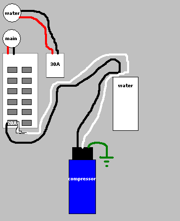 I'd like to know if it is code to do it this way, or what I would need to do to make it code legal. If I had the access I'd just run a new line of 10/2 w/ground, but it goes across a finished ceiling so I'm trying to reuse existing wiring.
|
|
#
?
Apr 7, 2008 15:48
|
|
|
Okay, I'm looking at building a 3x3x3 RGB LED cube, and I was thinking of using a faster PIC, the 16F88. Now, this one looks a LOT better for just about everything, but unlike the 16F628A I was using, it can't directly drive LEDs. With the 628A, I can just hook LEDs up, making things really simple. Is there some special thing I need to do to drive LEDs? I'd use Transistors, right? NPN-type? It sounds like it'd be a lot more complex... Mind you, I'm already looking at a massive wiring nightmare - 9 pins to select which LED, 3 pins to pick R/G/B.. Main difference: 16F88 can run at 8Mhz, the 16F628A at 4Mhz. Alternately, there's the Atmel microcontrollers, but I don't have a programmer for those (unless a Kit149 can do that). I also see a lot of hype about these Arduino boards. But those seem to just run Atmel stuff, and they call it "physical computing". Buzzwords ahoy! Anyone have experience with these? What can I say, I like flashy-blinky things I can make myself. :P TwystNeko fucked around with this message at 10:49 on Apr 8, 2008 |
|
#
?
Apr 8, 2008 10:46
|
|
|
Finished the triple CREE headlight. The hardest part was just making all those connections inside the aluminum housing. 3x CREE Q5-bin 1000ma BuckPuck driver 16x AA NiMh battery pack Should put out around 600 lumens for 3 hours. On the test drive just now, it was fun freaking out pedestrians who didn't know what the gently caress that was coming towards them. Kind of heavy, though, I'll probable switch to a handlebar-mount soon.   
|
|
#
?
Apr 9, 2008 04:10
|
|
|
Could someone help me out with a simple (I think, I'm probably missing something fundamental here) question on power switching? I'm puttering around with stepper motors and was reading through this: http://www.cs.uiowa.edu/~jones/step/circuits.html#practvr The left diagram in fig. 3.7 is what I'm looking at. I understand *how* it works but not necessarily why you have to use a buffer (aside from protecting the logic circuit from the motor windings in the event the transistor fails). If the logic level is 5v all around and your control can sink the 10mA, couldn't you just directly control the transistor, say from a PIC, without the buffer?
|
|
#
?
Apr 9, 2008 15:52
|
|
|
Yeah, it's just there for protection, and to define the requirements of the driver circuit. quote:The 7407 buffer used to drive the darlington may be replaced with any high-voltage open collector chip that can sink at least 10 milliamps. So long as your driver meets this requirement you should be fine.
|
|
#
?
Apr 9, 2008 15:59
|
|
|
TwystNeko posted:
I've got one coming in the mail, I'll let you know how it goes. I'm pretty sure you can also use it as a programmer for other AVRs. I also go a bit rolleyes at some of the press it gets, but at least some neat stuff is getting made by people who normally wouldn't touch a microcontroller. The prospect of being able to throw together five lines of C style code and have a running doohickey was what tempted me. From now on my giant pile of sampled PICs are going to be relegated to single purpose/timing critical things like PWM.
|
|
#
?
Apr 10, 2008 03:22
|
|

|
I was thinking about making a series of posts each constituting a lesson or two on common circuits and techniques, eventually culminating in combining them into something cool. I had three different things in mind: DIY switching power supply, which would cover the following: Comparators and hysteresis Relaxation oscillators Voltage controlled PWM Switching supply theory Voltage references Error amplification Closed feedback loops DIY DC motor speed controller: Pretty much the same as above, except replace Switching supply theory with H-bridge theory DIY linear regulators: Zener diodes Transistor lesson Voltage references Error amplifiers Closed feedback Reply if you're interested in this. I'd rather not start on such an endeavor unless there is some demand.
|
|
#
?
Apr 11, 2008 16:32
|
|


|
mtwieg posted:I was thinking about making a series of posts each constituting a lesson or two on common circuits and techniques, eventually culminating in combining them into something cool. I had three different things in mind: Yes! Can you do pwm or how to control a motor? I tried hooking up a pwm circuit to a motor but all it did was flip back and forth, rather then moving in one direction.
|
|
#
?
Apr 11, 2008 17:13
|
|
|
yes, there is a demand for that. Please do it.
|
|
#
?
Apr 11, 2008 17:34
|
|
|
mtwieg posted:Reply if you're interested in this. I'd rather not start on such an endeavor unless there is some demand. Ooh, I'd be interested in the switching power supply one. Any one will be nice though - it's always nice to learn more!
|
|
#
?
Apr 11, 2008 18:43
|
|

|
mtwieg posted:I was thinking about making a series...
|
|
#
?
Apr 11, 2008 19:17
|
|

|

|
| # ? Apr 27, 2024 03:25 |
|
|
I just wowed and amazed my co-workers by hardwiring a laptop power supply to the broken jack on a 3-month old Compaq that somebody brought into the PC repair side. "2 hours billable" beats "Sorry, we can't fix that." They're tickled pink. Learn to solder, learn electronics, and know the right time to show your hand and you'll make a tech's day.
|
|
#
?
Apr 11, 2008 20:29
|
|


