


|
Spatial posted:What's a decent chip for audio output? At the moment I'm using a CS4344 directly attached to a pair of headphones. It's fairly quiet I'm guessing because it's supposed to be paired with an amplifier. Still, cool as hell to hear it working. Are you specifically looking for I2C? Have you worked with it before? In my experience it can be surprisingly finicky for such a ubiquitous standard, at least to handle it properly for long-term stability. If you're familiar or not writing your own drivers, then no worries, but I would classify it as a "gotcha" if you're new to it and don't have other options.
|
 #
?
May 27, 2020 20:52
#
?
May 27, 2020 20:52
|
|


")

|

|
| # ? May 3, 2024 22:00 |
|
|
Ideally no controls at all would be best, like the CR4344 where it just determines the sample rate from the clock, but most multimedia stuff seems to be I2C so it's hard to avoid. I don't have a free SPI bus to use either. But yeah I'm used to that kind of nonsense, it's actually my job 
|
|
#
?
May 27, 2020 21:13
|
|

|
Out of curiosity, what do you find finicky about I2C? It seems like for digital MCU comm, there are 2 modern standards (I2C and SPI), and how easy each is to set up is mainly dependent on the drivers for the specific device, and controller/lib. I ended up switching from an SPI ADC to I2C, mainly since the latter one had better driver support for my toolchain. Anecdotally, most of the SPI devices I've used use arbitrary GPIO pins on top of the usual SCK, MOSI, and MISO, which is awkward.
|
|
#
?
May 27, 2020 21:43
|
|

|
Dominoes posted:Out of curiosity, what do you find finicky about I2C? It seems like for digital MCU comm, there are 2 modern standards (I2C and SPI), and how easy each is to set up is mainly dependent on the drivers for the specific device, and controller/lib. I ended up switching from an SPI ADC to I2C, mainly since the latter one had better driver support for my toolchain. There's a few bugs in the Arduino I2C library, and similar bugs are often found in other microcontroller libraries. The bugs usually involve a bad packet causing the i2c to completely lock up, but it usually takes 8 hours or more of continuous operation before you see it. It's a real pain in the rear end and it's put a lot of people off i2c altogether. SPI can be trickier to get set up, as so many manufacturers handle it a little differently, but once set up it always works
|
|
#
?
May 27, 2020 22:08
|
|

|
Yeah the chip select in SPI can be annoying if you don't have many GPIOs (multiplexers are a thing though) but it makes the protocol a lot simpler.
|
|
#
?
May 27, 2020 22:15
|
|

|
There's a lot that can go wrong with I2C, it trades wires for extra complexity. I can hardly remember a single chip I've worked on that didn't have some serious I2C errata. Clock stretching is a common favourite. One is nearly EOL at this point and they still find new bugs in it lol I've written drivers for some pretty lovely SPIs as well though. One was so bad it took multiple months to get it 100% stable - just an endless stream of timing bugs that would only trigger after tens of hours of testing. Total garbage.
|
|
#
?
May 27, 2020 22:41
|
|
|
I actually managed to get my hands on the hardware designer's testbench for that SPI peripheral; all the tests were in loopback mode, single transfers, with full chip resets between each test. Truly designed for reliability
|
|
#
?
May 27, 2020 22:44
|
|
|
Embedded is all trash, we should get rid of it
|
|
#
?
May 27, 2020 22:48
|
|

|
Why are we talking about I2C? I2S != I2C. I2S is an unfortunately named different standard for moving audio streams between chips
|
|
#
?
May 27, 2020 22:54
|
|

|
The original discussion was about an I2C-configured IC that used I2S for the actual audio data, I think?
|
|
#
?
May 27, 2020 22:56
|
|

|
Yep. v v v
|
|
#
?
May 27, 2020 22:59
|
|
|
That's a pretty good reason. I've never had many problems with I2C things, but I've never had to deal with running it particularly fast or ever had a device that requires clock stretching.
|
|
#
?
May 27, 2020 23:13
|
|
|
The original spec and a lot of even modern hardware is max 400kHz, which is another reason people hate I2C.
|
|
#
?
May 27, 2020 23:19
|
|
|
I think I have my first polished thing done. Investigating the use of epaper devices as a screen for environmental sensors. I'm thinking it could look nice and have a long battery life, but need to figure out how the refresh issues could cause problems. I published high-level drivers for Python, Rust, and C++ that wrap the ADC's drivers. Trying to see if I can build a kalman filter into these to make it work with cheap or old sensors. I noticed that there are a few existing things like this, but the most popular one takes a diff approach, where it outputs pH directly from an onboard MCU, while this outputs raw (digitized) voltages, and does the calcs using opensource software drivers. The former approach should be easier to adapt to rando languages/platforms, but I think this approach is more flexible as I can patch it, users can see how the code works and customize none/some/all as required. I've also noticed that some recommendations online advice using a DC offset of the voltage, then comparing it to ground, but I couldn't get that working, and it seems like this is a natural application for the ADC's differential feature. I literally couldn't have done this without y'all. I have so many JLC complementary electrical tape rolls due to all the fuckups. I mean, how do you just forget to wire the power pin? Dominoes fucked around with this message at 00:39 on May 28, 2020 |
|
#
?
May 28, 2020 00:32
|
|
|
That Works posted:Thanks. So relays have two voltage ratings: coil voltage and contact voltage. SSRs are much the same. The module I linked will turn 12V on and off (contact voltage) with a 3.3V signal (coil voltage). If you apply a 5V signal to the coil, it can switch much higher voltages easier. I have used that exact module to switch 12V with a 3.3V system (ESP8266). The relay module was used as per the attached image. When 3.3V is applied to the FORWARD pin, then Relays 1 and 4 turn on. Relay 1 connects battery+ to the + of the motor, relay 4 connects battery - to the - of the motor; the motor moves forward. Voltage is then removed, and the motor is free to coast. When 3.3V is applied to the REVERSE pin, then relays 2 and 3 turn on. Relay 2 connects battery - to the + of the motor, relay 3 connects battery + to the - of the motor, the motor moves backwards. If you apply 3.3V to both FORWARD and REVERSE, then you connect battery + to battery - through all your relays, and the smoke comes out of them.
|
|
#
?
May 28, 2020 01:16
|
|


babyeatingpsychopath posted:So relays have two voltage ratings: coil voltage and contact voltage. SSRs are much the same. The module I linked will turn 12V on and off (contact voltage) with a 3.3V signal (coil voltage). If you apply a 5V signal to the coil, it can switch much higher voltages easier. I have used that exact module to switch 12V with a 3.3V system (ESP8266). Thank you that's way more clear now. I saw a 5 volts in the description and confused coil for contact voltage.
|
|
|
#
?
May 28, 2020 01:24
|
|


|
Splode posted:There's a few bugs in the Arduino I2C library, and similar bugs are often found in other microcontroller libraries. The bugs usually involve a bad packet causing the i2c to completely lock up, but it usually takes 8 hours or more of continuous operation before you see it. It's a real pain in the rear end and it's put a lot of people off i2c altogether. SPI can be trickier to get set up, as so many manufacturers handle it a little differently, but once set up it always works
|
|
#
?
May 28, 2020 01:32
|
|
|
That Works posted:Thank you that's way more clear now. I saw a 5 volts in the description and confused coil for contact voltage. Reading the reviews: Beware of this module. The one I got switches 12VDC fine, but other people got ones that won't switch DC. The electronics on the board are powered by 5V, so the D+ pin gets +5V, and the D- pin gets GND. CH1-CH4 are the 3.3V inputs. I have another sainsmart 4-relay module that works exactly the same, except it's mechanical relays onboard. 5V to the VCC/GND pins, then IN1-IN4 will switch 3.3V logic. I really like SainSmart; they've never done me wrong.
|
|
#
?
May 28, 2020 02:02
|
|
|
was looking for practical projects to work on and found this profoundly delightful resistor tester/multimeter- https://www.robotroom.com/Minifigure-Multimeter.html the lego dude is wired up such that you press the resistor into his hands to complete the circuit and determine the resistance- but instead of outputting the result to a boring ol 7-segment lcd display or what-have-you, it uses text-to-speech to read the values aloud. consider me charmed, with a side of "that's actually decent design beyond mere art/aesthetics" Ambrose Burnside fucked around with this message at 03:41 on May 28, 2020 |
|
#
?
May 28, 2020 03:33
|
|

|
The Lego part is awesome but having to be plugged into a computer seems like a giant pain in the rear end. I think you should improve it with the guts of one of these component testers and maybe that TI voice synthesizer chip from the speak & spell.
|
|
#
?
May 28, 2020 04:18
|
|
|
i'm overlooking the usual minor quibbles i think b/c the successful + effective marriage of niches as wildly-disparate as "self-furnished + effective bespoke diagnostic devices, the sort of thing you always wanted to build [naturally] but never had an excuse" and "folksy, benevolent Lego sculpture" is just so satisfying
|
|
#
?
May 28, 2020 04:39
|
|
|
yeah I got to the part where the guy was like "the software is written in .NET because .NET is much easier to write and debug than embedded C" and I was like jesus  One of my students this semester, someone who had never touched a programming language or soldering iron before, managed to get her Arduino project doing reliable speech recognition. Not just synthesis -- recognition. That guy's got no excuse (it is very cool though)
|
|
#
?
May 28, 2020 04:41
|
|


|
Yeah I'm not trying to poo poo on it or anything, I just know that having it tethered to a computer would drive me insane. But thinking about it I suppose that he probably did it more for the journey than to actually use it.
|
|
#
?
May 28, 2020 04:48
|
|
|
Sagebrush posted:yeah I got to the part where the guy was like "the software is written in .NET because .NET is much easier to write and debug than embedded C" and I was like jesus he's right though .net micro framework rip in peace
|
|
#
?
May 28, 2020 05:14
|
|

|
Oooh I2C chat, I had a weird one recently. My MCU is normally the master on a bus, but during startup the DSP uses the I2C bus to read its program code from an EEPROM. This happens immediately after RESET, so my code just waits a while after reset to let the DSP boot. This wasn't working reliably, a few times it would boot, but mostly it wouldn't boot. After scoping the signal, it turns out the I2C peripheral in the STM32F303 was continuously stretching the clock on that bus when the DSP tried to initially access the EEPROM. Still not sure why that happened, the I2C peripheral was configured and idle. I solved it by disabling clock stretching on that bus (not needed anyway), but weird behavior that I haven't seen before.
|
|
#
?
May 28, 2020 08:35
|
|


|
If anyone's interested in Rust on microcontrollers, here's an up-to-date quickstart I put together, with minimal setup instructions. It's configured for a STM32 F3 series, but switching is usually an issue of swapping out HAL libraries. Rust is usually mentioned compared to C/++ in light of its memory safety and forced error handling, but I prefer it mainly for the streamlined experience and tooling.
|
|
#
?
May 28, 2020 15:36
|
|
|
designing my first 'pcb trace', and by pcb i mean "delicate spiderweb of copper film cut from conductive tape with a Cricut drag-knife". eagerly looking forward to learning some extremely stupid habits due to what I'm calling "tonka truck-type design constraints" that are required to produce a sufficiently-durable design that'll survive the transfer from the tape backing to its permanent backer material. it's like toddler-proofing a normal pcb trace
Ambrose Burnside fucked around with this message at 15:46 on May 28, 2020 |
|
#
?
May 28, 2020 15:42
|
|
babyeatingpsychopath posted:So relays have two voltage ratings: coil voltage and contact voltage. SSRs are much the same. The module I linked will turn 12V on and off (contact voltage) with a 3.3V signal (coil voltage). If you apply a 5V signal to the coil, it can switch much higher voltages easier. I have used that exact module to switch 12V with a 3.3V system (ESP8266). I have solved the next problem only to find a new one. The good news is I am only 1-2 problems away from being completely done with this project! It turns out I had ordered a motor controller over a month ago after going through some different tutorials etc and didn't realize it had arrived (was sitting in an unlabelled plastic bag on the back of my workbench). Anyway, it's not the Saintsmart you suggested (I have ordered that one now) but its similar and there was a tutorial for it. https://smile.amazon.com/gp/product/B01CC8XI60/ref=ppx_yo_dt_b_asin_title_o06_s00?ie=UTF8&psc=1 https://www.electronicshub.org/raspberry-pi-l298n-interface-tutorial-control-dc-motor-l298n-raspberry-pi/ Following the wiring instructions there:   And a script that fires off the enable pin "en" and either "in1" or "in2" I was able to contract and extend the linear actuator! New problem though  The LA needs to run for 30s to fully extend or contract (300mm stroke length, 10mm/s movement rate). The motor has a 25% duty cycle listed so I've been careful to let it rest for more than enough time between tests. I updated my scripts to run for 40s to either extend or contract and the 2-3x I have tried the motor will run but only for a couple seconds and then stop. I tried using the same script to light up an LED bulb on the breadboard and those worked fine so the Pi output is OK. I also took the LA and hooked it directly to the 12VDC source and it runs and fully extends / contracts just fine. I'm no expert, but the wiring to the motor controller etc and to the Pi all seems good, I don't think it's a loose connection. It's all premade jumper wires that work fine or alligator clipped wires. Could it just be that this motor controller is not great, or is there something going on that I have no idea about?
|
|
|
#
?
May 28, 2020 20:14
|
|
|
How hot is that heatsink getting? Careful, sometimes they can make your finger sizzle like bacon. It sounds like either: Your actuator's current draw is causing the LM298 or whatever to go into thermal shutdown, or your jumpers have intermittent contact when the table they're on is vibrating.
|
|
#
?
May 28, 2020 20:42
|
|
ante posted:How hot is that heatsink getting? Careful, sometimes they can make your finger sizzle like bacon. After leaving it plugged in and cycling the script 5-6x every 40s after it stops, the heatsink is barely warm to the touch. Likewise the Pi and the rest of the board etc as well as the LA motor housing etc are all cool or barely warmer than room temp. After seeing your post I put the LA on a pillow on a chair below the table I am working on and also went around and re-seated every wire etc. Same issues. If I tell the LA to run for 40s each time with the script it will run for anywhere from 1 to ~7 seconds then stop. I've noticed if I wait a little longer (40+ seconds) before trying to run the script again generally the LA will run a few seconds longer before stopping. When I try to run it as soon as the 1st command ends that's when it runs for even less time or on a few occasions won't run at all.
|
|
|
#
?
May 28, 2020 21:47
|
|
|
It looks like you don't have a ground connected between the Pi and the board? That can cause all manner of weirdness, run another lead from the screw terminal to a ground on the Pi.
|
|
#
?
May 29, 2020 00:14
|
|
|
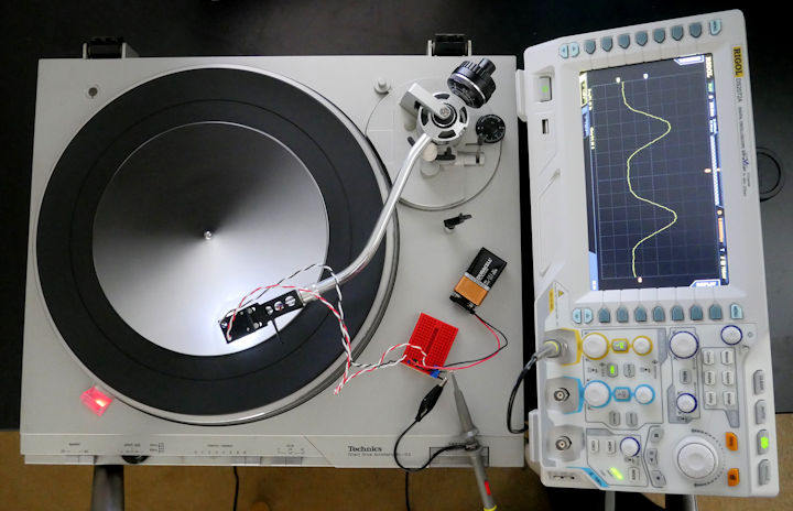 i suppose that IS one way to approximate a waveform generator, sure, why not the needle has been replaced by an LED + light sensor, and the 'disc' is a paper wheel with a gradient reflecting the desired waveform printed onto it.  guess the waveforms! 1. square wave, low frequency 2. square wave, higher frequency 3. "random noise" 4. sawtooth 5. triangle 6. sine Ambrose Burnside fucked around with this message at 00:32 on May 29, 2020 |
|
#
?
May 29, 2020 00:24
|
|
Forseti posted:It looks like you don't have a ground connected between the Pi and the board? That can cause all manner of weirdness, run another lead from the screw terminal to a ground on the Pi. The white jumper wire in my photo is connected to ground at pin #6 on the Pi. It's also screwed into the (-) block together with that black wire which comes directly from the 12V battery. I just double checked and both pins are screwed down and don't come out with a pretty solid pull on them. Could that still be a problem somehow? e: I tried it at 2 other ground GPIO pins (14 and 39) and also tried it with a different jumper wire. Same issue, runs a couple seconds, stops, if I try to run again right away it just doesn't run at all. ee: Thank you all for helping me troubleshoot dumb stuff and help me get my head around this. I am only 1-2 more steps from having all the pieces working and then I can combine everything and have it done. That Works fucked around with this message at 00:30 on May 29, 2020 |
|
|
#
?
May 29, 2020 00:27
|
|
|
Ambrose Burnside posted:
that's rad
|
|
#
?
May 29, 2020 00:36
|
|


|
what if a cam, except optical
|
|
#
?
May 29, 2020 00:38
|
|
|
That Works posted:The white jumper wire in my photo is connected to ground at pin #6 on the Pi. It's also screwed into the (-) block together with that black wire which comes directly from the 12V battery. Oh, I thought it was in the next one over at a glance, oops. It's probably good enough for testing, and if it were an intermittent connection I wouldn't expect it to have such a repeatable failure mode. It sounds like something is capacitively coupled. Is that board providing +5V power or meant to be connected to a +5V source? I'm guessing provides from the voltage regulator I see there. Test it with a multimeter if you have one but if it's giving you regulated +5V I'd power the Pi Zero from that instead of the USB and give it a try. Edit: Expanding on that, what is your power supply for the Pi? They're notoriously finicky, especially when you have external things hooked up to it. Mine only works well with the 2.5A one specifically made for it. Forseti fucked around with this message at 00:44 on May 29, 2020 |
|
#
?
May 29, 2020 00:41
|
|
|
 Well that wasn't that bad. I mean the process, the result I'm sure is. It's very simple digital stuff although it's starting to look like making this work on a single layer board could be a problem. I'm also a bit confused about the power though. The red block with C4/C5 is based on Espressif's recommendation but wouldn't the capacitance be just the sum of them, so almost imperceptible addition to C4, and wouldn't I get the same result by just increasing C2? They're also suggesting the green block for pulling "Chip enable" up, but the R1 and C3 values were TBD. I guess a 100k for R1, but I don't see if/why C3 is necessary anyway if I just need to pull up the pin to run it.
|
|
#
?
May 29, 2020 01:17
|
|

|
If you're making a shitload of them it's cheaper to use two of the same value that you already use elsewhere than to add a new part. Electrically C2 is at the same point but you also usually have decoupling caps right next to your ICs as well.
|
|
#
?
May 29, 2020 01:25
|
|
|
That Works posted:The white jumper wire in my photo is connected to ground at pin #6 on the Pi. It's also screwed into the (-) block together with that black wire which comes directly from the 12V battery. Check the crimp on your alligator clip leads. I had a cheap set that didn't have any exposed copper and just relied on the puncture through the insulation. I could easily see that causing problems with non-zero amperage.
|
|
#
?
May 29, 2020 01:55
|
|
|

|
| # ? May 3, 2024 22:00 |
|
|
What's the best way to track the amount of line being paid out from/wound onto a drum? It's not entirely linear because of the line building up on the drum and increasing the effective diameter, which makes it difficult to sync with another one doing the opposite thing at the other end. Is using a rotary encoder with its own pulley to measure the linear amount directly going to be a good solution here?
|
|
#
?
May 29, 2020 06:04
|
|

