|
Not Wolverine posted:Thanks for the suggestion, I will search engines some more. I do for sure want 20a just in case I plug this into a 20a outlet, my "shop room" where I plan to use this has 20a outlets. In Addition, I would also prefer to use dual like switches to be able to discount both the hot and neutral lines, I know that is not necessary but I would feel more safe in case there was a fault either in my box of the wiring somewhere else. I don't like doing a lot of dumb stuff with mains voltages, but I do use older lower tools and if another device started messing up and sending current down the neutral line instead of it's equipment ground then I would like to have the neutral disconnected on my own hack job box. If you're going to be mains powered, get a purpose-designed power entry module with a switch, fuse holder, and (maybe) EMI filter. Then choose the smallest fuse possible and you won't have to size the inside-equipment switches for max breaker current. Digikey Stack Machine posted:I'm not saying you shouldn't spend an extra 50c and get a 20A switch; it'll last longer regardless. I'm not even saying you're making this claim but there is a common misconception that things connected to an X amp outlet have to be able to handle X amps. The voltage rating on outlets is what they supply, and there's no way to get less than 120V from a 120V outlet. The current rating is a maximum, do-not-exceed thing and a 20A outlet will happily give you 15A or 1A, and if you plug the same widget into two different 120V outlets it will take the same current regardless of the current rating of the outlet. All of this is to say that a 15A switch should be OK for anything safe with a NEMA-15 plug attached. Leaving EE-land into electrician-land, everything downstream of a protection device should have larger ampacity than the protection so that it's fine in all situations where the breaker hasn't tripped. So if you are behind a 20A breaker, you want a fault that somehow causes it to draw 19A to not start a fire since the breaker will never trip (why code lets you put 15A wiring behind 20A breakers when everything else like that is forbidden has never made sense to me as anything besides historical lazyness)
|
 #
?
Jan 20, 2021 19:38
#
?
Jan 20, 2021 19:38
|
|


|

|
| # ? Jun 11, 2024 00:43 |
|
|
Forseti posted:Re: seawater that's the only part of the board that's really messy I thought I was seeing rust in the heat sink mounting holes, and the effect in the solder looked like some sort of pitting that had been cleaned up... I'd also believe leaky water cooling, bad batch of solder paste at the factory, maybe another ground path through a connector or something getting disconnected so that trace carried an unexpectedly-high current for a while, but that one seems less likely because I wouldn't expect that board to be ordinarily sold with a bunch of flux left on it. E: Foxfire_ posted:Leaving EE-land into electrician-land, everything downstream of a protection device should have larger ampacity than the protection so that it's fine in all situations where the breaker hasn't tripped. So if you are behind a 20A breaker, you want a fault that somehow causes it to draw 19A to not start a fire since the breaker will never trip (why code lets you put 15A wiring behind 20A breakers when everything else like that is forbidden has never made sense to me as anything besides historical lazyness) Good points. So either the fuse goes before the switch or the switch is rated for 20A. This is good and reasonable and I have some lamps to throw away now. Stack Machine fucked around with this message at 00:21 on Jan 21, 2021 |
|
#
?
Jan 20, 2021 19:39
|
|

 . Like the face plate/screws/ports/edge connector all look fine.
|
Cory Parsnipson posted:I'm just winging it tbh. So far the most complicated thing I've done is replace a thumbstick in a joycon. Oh absolutely using a kit, because otherwise would have zero clue where to start and yes sounds like a great idea to deep dive into the scenesters and listen to their feedback. Also thanks for those links.
|
|
#
?
Jan 21, 2021 15:04
|
|


|
Stack Machine posted:Good points. So either the fuse goes before the switch or the switch is rated for 20A. This is good and reasonable and I have some lamps to throw away now. I went down a rabbit hole because I was pretty concerned about this since in North America it's really, really common to have switches in un-fused fixtures with ratings much lower than the circuit breaker trip current. I'm talking pull-chains and these kind of inline switches that I have in just a ton of things:   I was beginning to think maybe they were onto something over in the UK with those fused plugs, and maybe they really they are, but I would settle for some reassurance that the switches wouldn't be the first thing to fail if some fault made something downstream just start dumping out about 2kW as heat all of a sudden. It turns out that UL standards have that covered for all of those little low-rating switches, and one of the tests is just cranking the conventional fusing current listed in this table through them for an hour to make sure they'll survive it, clearly intended to be the fusing current of the highest-rated circuit they could be connected to:  So the switch itself won't catch fire, but I think it's also not guaranteed to still work correctly (and not be a fire hazard) after such a fault, or interrupt the circuit if you try to flip it during such a fault. So if my lamp ever starts smoking I'm yanking the cord. (Also I should still probably get some better lamps.)
|
|
#
?
Jan 21, 2021 19:49
|
|
|
Quoting myself from the raspberry pi thread:FISHMANPET posted:Hey, question about powering my Raspberry Pi. I'm building a project and the whole thing is powered by a big 5V 5A AC-DC Adapter. It's a pretty basic one I picked up on Amazon, so I wouldn't trust it to always perfectly output exactly 5V. I know I can put 5V directly onto one of the 5V pins on the Pi to power it, and that's worked well enough for me as I'm testing and building this out. I'm driving a display over I2C and a neopixel ring light, which all require the data to be 5V. I've got a level shifter that converts the 3.3V signals from the GPIO pins to the 5V the peripherals require, and it gets set to 5V by an input voltage. For this thread, I'm wondering what the voltage tolerances are for I2C, and specifically will a potentially fluctuating 5v-ish signal cause any troubles? Trying to figure out if I need to worry about driving my level shifter off a clean 5V from my Pi, or if driving the level shifter directly off my 5V adapter will be good enough? Specifically I'm just driving this screen with i2c, and this bi-directional level shifter. So in this case the voltage of the HV1-HV4 data channels will just be whatever voltage I connect to HV.
|
|
#
?
Jan 22, 2021 19:39
|
|

|
I don't think you need to worry about voltage fluctuations for a couple reasons. At least with the Pi 3 and earlier (haven't looked at the 4 schematic) the difference between powering over USB and powering through the header pin was just bypassing a fuse. Not a huge deal. The SoC also gets regulated 3.3 / 1.8v so that's not an issue
|
|
#
?
Jan 22, 2021 20:05
|
|

|
Yeah you're fine. Among other reasons because the high/low levels for I2C are defined as fractions of the supply voltage, so even if it drifts around a bit the threshold between high and low levels will drift along with it.
|
|
#
?
Jan 22, 2021 20:42
|
|
|
if i want to transmit "a couple of amps or so" through a continuously-rotating member, it's a slip ring or bust, right? also, the current rating of a slip ring constrained by the ring component instead of by the wiring itself, right? i.e, I cannot just splice multiple wire channels together to increase its carrying capacity like i might do elsewhere because the slip ring component itself acts as a bottleneck for all channels (i'm trying to set up an electroplating bath such that the to-be-plated cathode is continually rotating while plating is occurring; it'll end up somewhere cool if it works out like i'm hoping)
|
|
#
?
Jan 24, 2021 23:05
|
|

|
you could ionize the air in between the rotating members and transmit the power as an electric arc perhaps
|
|
#
?
Jan 24, 2021 23:11
|
|

|
You could use a transformer split between the rotating and nonrotating parts, I think. For AC
|
|
#
?
Jan 24, 2021 23:19
|
|


|
A standard cheap commercial slipring will be some thin gauge copper fingers brushing up against a copper plate. That's reeeeaaally not conducive to high amounts of power, every time it loses contact for a fraction of a second, it'll arc and erode away a little bit of the copper. Basically, sliprings are really nice concept, but they're actually really terrible hacky solutions. Brushed motors get around this by pressing carbon blocks (brushes) against the other conductor, with a spring, and they are consumable as they slowly wear away. So I present your five options: - Buy a really expensive slipring - Limit your rotation to less than 360 degrees and just use wires with a bunch of slack and wire guides - Take apart a DC motor and hack it to be a slipring (my favourite for reasonableness of approach) - Make your own from scratch - Use two motors end-to-end, one for the rotation on the base, one attached to the moving portion as a generator. Not efficient, or easily controllable in terms of voltage / current. (my favourite for cool points)
|
|
#
?
Jan 24, 2021 23:55
|
|
|
Ambrose Burnside posted:if i want to transmit "a couple of amps or so" through a continuously-rotating member, it's a slip ring or bust, right? also, the current rating of a slip ring constrained by the ring component instead of by the wiring itself, right? i.e, I cannot just splice multiple wire channels together to increase its carrying capacity like i might do elsewhere because the slip ring component itself acts as a bottleneck for all channels Make it rotate back and forth instead of continuously in one direction, then just use wires. e: Or is rotating continuously important for reasons other than just getting motion to happen in the plating bath? I was kinda imagining you were just trying to get an even coat or keep bubbles from building up on the surface or something but re-reading your post it sounds like you're doing something weirder.
|
|
#
?
Jan 25, 2021 00:29
|
|

|
Shame Boy posted:e: Or is rotating continuously important for reasons other than just getting motion to happen in the plating bath? I was kinda imagining you were just trying to get an even coat or keep bubbles from building up on the surface or something but re-reading your post it sounds like you're doing something weirder.
|
|
#
?
Jan 25, 2021 00:43
|
|
|
just spin the world around your tank
|
|
#
?
Jan 25, 2021 00:49
|
|
|
ante posted:A standard cheap commercial slipring will be some thin gauge copper fingers brushing up against a copper plate. That's reeeeaaally not conducive to high amounts of power, every time it loses contact for a fraction of a second, it'll arc and erode away a little bit of the copper. i assumed sliprings would use the same construction as brushed motors, good to know the cheap ones don't meet that standard. i'm leaning towards cannibalizing a DC motor or building one from scratch, yeah. total DIY approach is where my heart lies, of course, but i think it makes sense. I don't think I have any brushed DC motors i can gut so I'm gonna have to buy -something-, and if it's a scratch build I can just buy the carbon brush+spring replacement packs and build it out from there, drive the rotor component with a sheathed copper rod (insulating coupler between motor and rod) and have the brushes bear directly on it, that sort of thing. that said, i think the best-fitting solution here hasn't been mentioned- a brushless approach, yeah, but not wireless. use a liquid metal bridging the rotor and stator to transmit electricity. i'm going to be buying at least two specialty fusible alloys for making electroforming mandrels and for backfilling electroformed shells to produce incompressible metal tooling, I can just tack some gallium (or another low-temp fusible alloy tailored for use in electrical contacts/switches, gotta do research here) onto my order and then 3d print a coupler-reservoir dealie to suit whatever I come up with for the torque transmission. wrt performance/suitability, liquid metal sliprings seem to offer the smoothest and least-interrupted connections by far between the standard slipring designs, and that seems important if I want consistent and repeatable plating bath performance, iirc current spikes will �burn� parts and cause pitting, which will gently caress the whole thing up. i'm probably understating the design challenges involved here. like. just off the cuff, if straight gallium/indium isn't suited to this I'll need some sort of heating element to melt the slipring's metal couple for it to function. i'm sure I can come up with some more complications if i take a minute... but i'm not even considering using mercury here, that means it can't possibly be a bad idea, i'm pretty sure. i know i can just buy the things ready to go, but a cursory googling says commercial mercury sliprings would run me at least $100 to get a hold of in any capacity, which is way over budget. don't seem like something that's easy to salvage. and i'm a sucker for DIYing poo poo like this, why lie Ambrose Burnside fucked around with this message at 02:03 on Jan 25, 2021 |
|
#
?
Jan 25, 2021 00:59
|
|
|
Ambrose Burnside posted:if i want to transmit "a couple of amps or so" through a continuously-rotating member, it's a slip ring or bust, right? also, the current rating of a slip ring constrained by the ring component instead of by the wiring itself, right? i.e, I cannot just splice multiple wire channels together to increase its carrying capacity like i might do elsewhere because the slip ring component itself acts as a bottleneck for all channels Why on earth would you need to rotate the thing you are plating? taqueso posted:If it is just for even coating reasons, you could spin the water instead of the part. This except instead of spin the water you could agitate it many ways if you're dealing with issues of uneven plating thickness or something.
|
|
#
?
Jan 25, 2021 01:00
|
|

|
Shame Boy posted:Make it rotate back and forth instead of continuously in one direction, then just use wires. nah, you've more or less got it. I've been working towards setting up my own little rapid tooling-type metal stamping die workflow for a while- 1. use a hobbyist resin 3D printer to make master tool patterns, 2. cast low-melting fusible alloys into/over the masters to produce electrically-conductive mandrels mirroring the master, 3. electroform copper over the mandrels to produce a high-detail shell (mirroring the mirrored mandrel and bringing us back to the master model geometry) that will serve as the working face of the tool, 4. melt out the fusible mandrel alloy to get a hollow shell, then backfill the shell with a different, rigid/dimensionally-accurate fusible alloy. 5. end up with a medium-duty, very high-detail composite die, produced quickly, cheaply and entirely without machine tools. 5a. as a bonus, both fusible alloys used are essentially infinitely reusable, so melted mandrels and backer alloy from worn-out/obsolete tools can be recast into new components with negligible loss. 6. use completed tooling in a generic 20-ton hydraulic press to very rapidly produce parts or finished goods, bridging artisanal production and mass-manufacturing this type of composite tooling- minus the dirt-cheap stereolithography masters that are now possible- has been widely used in manufacturing requiring smallish runs of many different discrete components, where cutting a steel tool is too slow and expensive. running shoe soles and car interior plastic parts were traditionally made this way for much of the later 20th century. similarly, here�s a flowchart of artisanal tooling production workflows for metalworkers circa 1990; i�ve added my own in on the right:  (tooling resins are out, fusible alloys are in) they were electroforming copper to make tooling back then, too, except it was solely used to produce a durable reference sample to be traced by a lathe replicator machine, and the master designs themselves still had to be hand-carved with old-fashioned talent and patience. i�ve adapted it to take advantage of $300 high-detail resin printers that consumer capitalism has blessed me with. point is, i�m an artisanal metalworker with a focus on sheet metal goods, i can easily spend 20 hours on a single item. so the prospect of being able to literally stamp out my own designs 50 times faster than i can currently produce sth- or just expedite the most boring parts of the hand-forming processes- while also making my own tooling from CAD designs at cost, is �extremely powerful�. but i've realized that this setup would also open other doors, particularly directly electroforming over resin prints to improve their mechanical performance and stabilize them long-term by sealing them off from further UV exposure. and then i found a research paper detailing how spinning electroforming mandrels during plating dramatically improves the consistency of plating thickness + eliminates most pitting/bubble surface defects, like, deposit thicknesses with less than 1% variability was achievable with their test rig. put these together, with my context of being a machinist with no current access to machine tools, and I'm thinking (hoping) that it's possible to produce metal-clad 3d prints with enough precision for machinist-calibre mechanical assemblies, think engines, pumps, gearboxes etc, particularly very small or difficult-to-machine designs. hobbyist resin 3d printers can't produce parts accurate to half a thousandth of an inch or w/e, but in principle you can slightly undersize the core and then plate metal over it to build it up to the final dimension. conventional plating isn't consistent or surface-finish-clean enough to work, but this rotary electroforming seems ideally- suited to producing axially-symmetric parts like pistons or cylinders. even if it isn�t, it seems like a straightforward and achievable way to significantly improve quality control in the plating process, which has always been the biggest question mark in this workflow. it�s very easy to throw a cosmetic copper sheen on something, but laying down thick, clean & well-anchored plating is something of an esoteric dark art people usually learn directly from someone else as a trade. i have no guarantee i�ll work out my plating setup well enough for it to do what i want, so i�ll take all the assistance i can beg/borrow/steal anyways my hail-mary end goal is something like �making a copper-resin composite wobbler steam engine the size of a sugar cube�. or trying, anyhow. if that doesn't work out I should still end up with a conventional electroforming setup that's suited to my original objectives of producing quick n cheap custom metal tooling + producing robust mechanical parts from resin prints; the only extras needed are the slipring and the motor, more or less. wrt spinning something else: it isn't just circulating/mixing the bath, the rotor and stator have to turn relative to each other to average out the differences in the bath's plating characteristics across the entire part. spinning the anode won�t average out the cathode�s... cumulative galvanoexposure?, or not necessarily (it would likely have to revolve around the cathode, which is probably trickier than just spinning the cathode on its own axis). if i tailored the anode specifically for building up the bores of cylindrical parts it would take the form of a copper tube/pipe around the cathode, and in that case either part could rotate, but the challenge is basically the same either way in that case Ambrose Burnside fucked around with this message at 04:33 on Jan 25, 2021 |
|
#
?
Jan 25, 2021 01:26
|
|
|
taqueso posted:You could use a transformer split between the rotating and nonrotating parts, I think. For AC This is a hard problem, primarily because air core transformers and transformers with big air gaps in them have low magnetizing inductance and terrible power factors, so you wouldn't be able to get 60Hz in without a lot of copper, a fancy core design machined to tight tolerances (think induction motor) or both. A wireless charging chipset could, however, get a significant amount of power across the gap efficiently using a very bad ad-hoc transformer, but maybe not enough for your electroplating application.
|
|
#
?
Jan 25, 2021 04:37
|
|
|
Ambrose Burnside posted:1. use a hobbyist resin 3D printer to make master tool patterns, Holy poo poo. Whenever you're done with this I want one.
|
|
#
?
Jan 25, 2021 04:43
|
|

|
Stack Machine posted:This is a hard problem, primarily because air core transformers and transformers with big air gaps in them have low magnetizing inductance and terrible power factors, so you wouldn't be able to get 60Hz in without a lot of copper, a fancy core design machined to tight tolerances (think induction motor) or both. A wireless charging chipset could, however, get a significant amount of power across the gap efficiently using a very bad ad-hoc transformer, but maybe not enough for your electroplating application. When I was looking at this for getting power onto a spinning part for a pov display (before I got lazy and stopped), napkin math was saying that coils drawn in PCB traces driven at kHZ would work okay across a few mm of air gap. Looking at premade wireless charging coils, they're mostly designed for 125kHZ and have ratings in 5-10A type range, so probably could be made to work.
|
|
#
?
Jan 25, 2021 06:19
|
|
|
If it's just for moving the fluid around, I would vote for just installing an impeller or something in the bath instead of whatever complicated stuff you have to do to move the part.
|
|
#
?
Jan 25, 2021 07:16
|
|
|
How about a roller/ball bearing with conductive grease? Pre-tension it to reduce any chance of arcing. It should be able to handle a couple amps easily. Edit: just keep it out of the solution so it doesn't seize.
|
|
#
?
Jan 25, 2021 14:15
|
|
|
Additional fun overcomplicated idea: Instead of spinning it in place, make a circular track above the tank that your holder thing travels around in, with a differential to keep the "car" always facing the same direction in space. Since it will just be moving in a circle rather than twisting relative to your workshop the wire won't ever twist itself up, but the part will still experience a constantly changing fluid flow direction which might actually be better for even plating than just spinning it around.
|
|
#
?
Jan 25, 2021 18:34
|
|
|
Stack Machine posted:This is a hard problem, primarily because air core transformers and transformers with big air gaps in them have low magnetizing inductance and terrible power factors, so you wouldn't be able to get 60Hz in without a lot of copper, a fancy core design machined to tight tolerances (think induction motor) or both. A wireless charging chipset could, however, get a significant amount of power across the gap efficiently using a very bad ad-hoc transformer, but maybe not enough for your electroplating application. Foxfire_ posted:When I was looking at this for getting power onto a spinning part for a pov display (before I got lazy and stopped), napkin math was saying that coils drawn in PCB traces driven at kHZ would work okay across a few mm of air gap. Looking at premade wireless charging coils, they're mostly designed for 125kHZ and have ratings in 5-10A type range, so probably could be made to work. FWIW I'm using a generic 5A bench supply for now, and most of the parts i'd be forming are relatively small wrt surface area (determines the current draw) and wouldn't draw anything close to that; for the precision plating stretch-goal stuff I doubt any part would ever draw more than an amp. So yeah, it could be practical. The bigger barrier to usingt this approach is probably my very thin EE-adjacent knowledge. Shame Boy posted:Additional fun overcomplicated idea: Instead of spinning it in place, make a circular track above the tank that your holder thing travels around in, with a differential to keep the "car" always facing the same direction in space. Since it will just be moving in a circle rather than twisting relative to your workshop the wire won't ever twist itself up, but the part will still experience a constantly changing fluid flow direction which might actually be better for even plating than just spinning it around. I considered that as the alternative to rotating, yeah. I didn't consider that it would let me avoid the slipring component, which is compelling. Would probably be easy to put together with two motors to skip the differential altogether, one rotating the whole car assembly in a circle, the second (a lil continuous-rotating servo, probably) replacing the differential and maintaining the "tracking", drive the whole thing with a microcontroller to keep it easy-peasy. I gotta workshop some of this stuff in CAD now, see what rises and what sinks.
|
|
#
?
Jan 25, 2021 19:01
|
|
|
Ambrose Burnside posted:FWIW I'm using a generic 5A bench supply for now, and most of the parts i'd be forming are relatively small wrt surface area (determines the current draw) and wouldn't draw anything close to that; for the precision plating stretch-goal stuff I doubt any part would ever draw more than an amp. So yeah, it could be practical. The bigger barrier to usingt this approach is probably my very thin EE-adjacent knowledge. The open-pools-of-mercury slipring idea is the best so far.  For low-amp and low-vibration, a brush/slipring will work just fine. Do you really need two rotating contacts, or can you have one stationary and one rotating? Having just one rotating member simplifies things an awful lot.
|
|
#
?
Jan 25, 2021 19:37
|
|

|
babyeatingpsychopath posted:The open-pools-of-mercury slipring idea is the best so far. And: only the to-be-plated cathode has to rotate, in fact I wouldn't want both to rotate b/c depending on the RPMs involved they could end up... what's the term, in phase? which would assumably work against an evenly-distributed plating thickness. Even if it's stationary, though, the anode's geometry will be important, and will be tailored to the part to some degree. Before the rotor cathode idea presented itself my plan was to average out the plating on the critical working face of the tool by producing custom anodes for each part to be plated, following the general contour of the tool face with a suitable offset. In a very tidy coincidence I can leverage the process resources to *also* produce the anodes efficiently with a CAD/3d print/fusible metal rapid tooling workflow: i'd cast simple single-use stamping dies from the fusible 'backfill' tooling alloy, and stamp the anodes from copper sheet with the hydraulic press. pure fusible alloy tooling isn't suitable for my sort of production work because it deforms too quickly, but it's fine for one or two parts if they don't have fine detail. and because the 'cathode' and 'anode' are both CAD-derived I should get very nice, closely-matched contours. sorta like this, shown in cross-section (excuse the graphics)  for small cylindrical parts I could still probably achieve good results wrt thickness specifically, without rotation, by using a copper pipe/tube anode placed around the cathode and fixtured on the same axis, but most of my parts aren't that accomodating. with a rotating cathode this all becomes far simpler, proximity gets averaged along the axis of rotation so as long as the cathode is parallel to that axis it won't 'favour' a particular pole. a length of wire, flat section of sheet etc would all work, just as long as they're fixtured parallel to the axis of rotation. Ambrose Burnside fucked around with this message at 20:26 on Jan 25, 2021 |
|
#
?
Jan 25, 2021 20:22
|
|
|
Ambrose Burnside posted:with a rotating cathode this all becomes far simpler, proximity gets averaged along the axis of rotation so as long as the cathode is parallel to that axis it won't 'favour' a particular pole. a length of wire, flat section of sheet etc would all work, just as long as they're fixtured parallel to the axis of rotation. Exactly my thought. Having a copper pipe/rod in the center with something rotating around it makes this whole setup loads easier. You can have a single bearing with multiple brushes/contacts to contact your cathode. I'm imagining a wheel that's driven from the outer edge, with a bearing and a nonconductive bushing with a rod in the center. The power supply has brushes touching at the rim/hub in several spots, with the part hanging from it, and then the other lead of the PS connects to the rod. This lets you up the current in all the parts that need to have high current.
|
|
#
?
Jan 25, 2021 21:59
|
|
|
I'm not sure if I'm using the right words for this, but do they make terminal blocks that gang together each side, instead of individual rows? 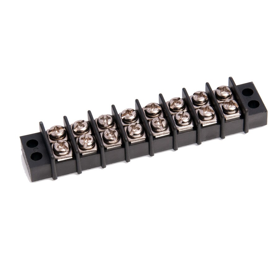 Like that, but horizontal, instead of 1-to-1? I mostly want something I can screw a row of positive and negative wires to.
|
|
#
?
Jan 27, 2021 18:33
|
|


|
Try searching for "busbar" or "busbar terminal block" https://www.littelfuse.com/products/other-products-and-accessories/busbars-and-terminal-blocks/common-busbar-screw-terminals.aspx 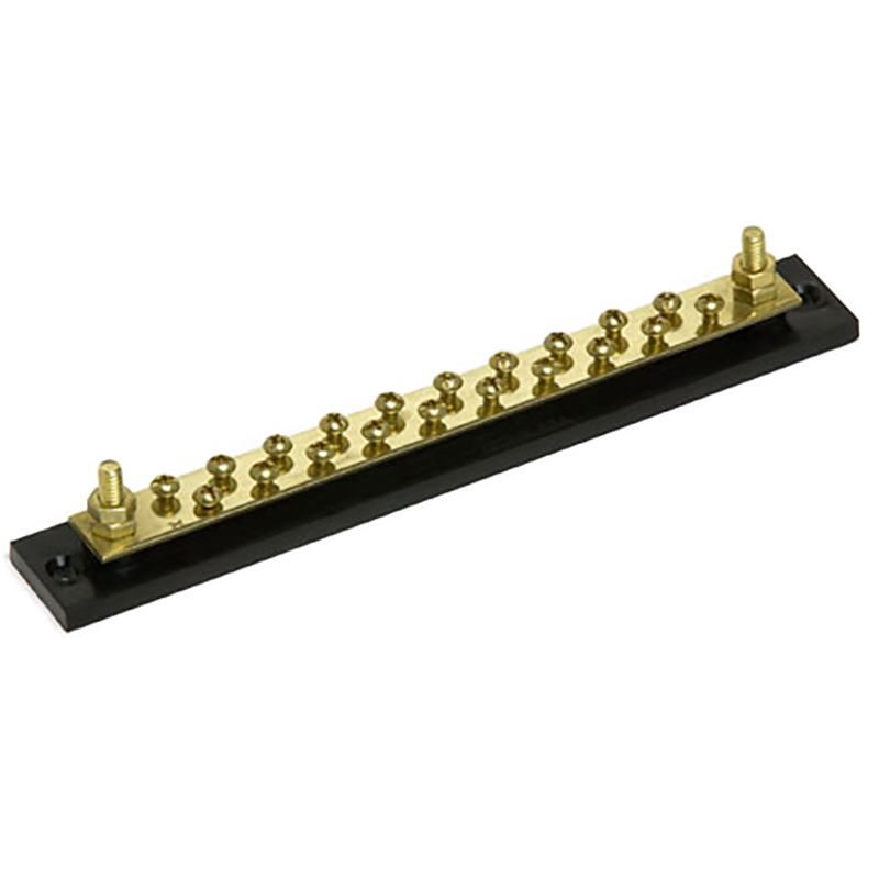
|
|
#
?
Jan 27, 2021 18:39
|
|
|
Harvey Baldman posted:I'm not sure if I'm using the right words for this, but do they make terminal blocks that gang together each side, instead of individual rows? Get the hell out of my head. I ended up buying this but it seems kinda weird to do it that way. What I'd really like is something in that same form factor, but the two sides are all connected, like you said, horizontally. Having to have two separate bus bars, one for + one for - seems kind of silly.
|
|
#
?
Jan 27, 2021 22:42
|
|
|
You can get metal things that hop over the barriers to connect two adjacent columns:
|
|
#
?
Jan 27, 2021 22:55
|
|
|
Forseti posted:I bought a cheap used AMD Firepro V4900 GPU off eBay and it works fine but I'm baffled by the way the solder has been all melted on this section of the board (not sure what it's called, I believe it helps EMI performance). It doesn't look like anyone was messing around with trying to replace caps or reflow the GPU or anything like that (and why would they, it's a wimpy workstation card that I paid $25 for) so my only guess is that the GPU overheated and it melted the solder? You can see what that area should look like in the pics of presumably another card from the same seller: https://www.ebay.com/itm/AMD-ATI-FirePro-V4900-1GB-GDDR5-SDRAM-PCI-Express-x16-Desktop-Video-Card-DVI-DP/184326344389
|
|
#
?
Jan 28, 2021 06:10
|
|


|
Feel free to super laugh at my beginnerness, but I think I've diagnosed a bad mosfet (shorted on all legs where it shouldn't be). A new mosfet is cheap, but the shipping isn't so I decided to take apart some trashed electronics in hope of finding the same or equivalent mosfet. The broken mosfet is a AO4409 and I found a site called alltransistors.com and it seems like one of the mosfets, a AO4948 should be an interchangable mosfet. Is it this simple or are the other factors that I need to consider? The broken mosfet in in the control circuit in a KSGER T12 soldering station if it makes a difference.
MrOnBicycle fucked around with this message at 15:18 on Jan 29, 2021 |
|
#
?
Jan 29, 2021 15:07
|
|
|
It looks like one of those is P-channel and the other is N-channel so that's a no-go. (One will pass current in the drain to source direction when the gate voltage is above the source voltage, the other is the exact opposite, passing current from source to drain when the gate voltage is below the source voltage.) Also the pinouts aren't compatible, with the source, drain, and gate in different places.
|
|
#
?
Jan 29, 2021 15:19
|
|
|
Stack Machine posted:It looks like one of those is P-channel and the other is N-channel so that's a no-go. (One will pass current in the drain to source direction when the gate voltage is above the source voltage, the other is the exact opposite, passing current from source to drain when the gate voltage is below the source voltage.) Also the pinouts aren't compatible, with the source, drain, and gate in different places. Ah yes I see that the pin-out is way different now when I found a datasheet for the 4948. Are there any good ways to finding compatible mosfets or should I just go through the data sheets of what I have until I find one that seems compatible?
|
|
#
?
Jan 29, 2021 15:27
|
|
|
MrOnBicycle posted:Ah yes I see that the pin-out is way different now when I found a datasheet for the 4948. Are there any good ways to finding compatible mosfets or should I just go through the data sheets of what I have until I find one that seems compatible? Datasheet analysis is the only way forward with salvage. There are simply too many parts that look similar. Even MOSFETs have a crazy variety of flavors with respect to current ratings, voltage thresholds, and (as you learned) pinouts. My go-to strategy for things like this is to find something else on Digi-key that you could use to make the shipping more tolerable (an Arduino, a Raspberry Pi, a tool, a breadboard). Randomly searching for a comparable part on other stuff is very needle-in-a-haystack. But no judgment if you prefer that. It's good for the environment and I can see it being a fun part of the hobby. Just know that it comes with a research backend.
|
|
#
?
Jan 29, 2021 15:40
|
|


|
I don't know if there's a big database someone maintains or some other easy way, but if you want to know which specs in the datasheet matter most, once you get past device type (n-channel or p-channel) and pinout, you need to make sure the replacement can tolerate at least as high a continuous current and Vds as the original, and has an equal or lower Rds_on at the same gate voltage, and has an equal or lower gate charge (usually written Qg). Sometimes these things matter more or less depending on the design of the circuit they're used in, but these are the main things. Maybe I'm overly pessimistic but I wouldn't be too hopeful of finding a suitable replacement unless you happen to have the same part laying around. There are tradeoffs in MOSFET design so unless you find a much newer part in the same package with the same pinout it'll be hard to meet or exceed every spec and if it met every one chances are the part number would be the same. Edit: Qg is an example of something that's probably less critical in a temperature control. My guess is this is a low speed PWM thing so if it takes 10x as long to turn on the FET it might not matter. If it turns out that it does matter, though, the FET overheats, so plan accordingly. Stack Machine fucked around with this message at 15:53 on Jan 29, 2021 |
|
#
?
Jan 29, 2021 15:49
|
|
|
Oh, and if you do decide to buy the same part, don't just buy one. You still don't know how this one died. (Another argument against salvage: if you find something close and it fails, it's hard to know whether it was the part being sightly off or some underlying cause for the original failure) KnifeWrench fucked around with this message at 16:23 on Jan 29, 2021 |
|
#
?
Jan 29, 2021 16:20
|
|
|
Thanks for the replies. I saw that the alltransistors.com searcher wasn't doing it correctly the first time. After I redid it, the 10 or so results were more plausible. I think I'll use the old boards to practice desolering and soldering and order some new transistors when I find other stuff I want/need to reduce the shipping % of the order. I really need to practice on poo poo I don't care about anyway. Pretty fun stuff this is, and for some reason people throw away tons of easy to fix / working electronics in my apartment building. So far I've found a iCloud-locked iPhone 5S which I bought a broken screen one for and repalced the logic board... and dropped it myself a month later. Also found a 2010 MacBook pro with a blown battery, broken charger and dud harddrive. So far repaired all of it (just need to install macOS on it for like $40. Found a mint Dell p2411h as well. Oh and a JBL Flip 3 with a broken charger. Board was too messed up to solder a new micro USB so I soldered a USB cable to it instead. Works great. Fun times!
|
|
#
?
Jan 29, 2021 16:35
|
|
|

|
| # ? Jun 11, 2024 00:43 |
|
|
Hey, I recently ran into a problem with my fancy headphones, and I was wondering if you guys can help me out with fixing it. When the headphones are plugged in using an inline 3.5mm audio cable, the speaker in the left ear cup only plays a flat monotone sound. However, when the headphones are connected via bluetooth instead of an aux cable, the speaker operates just fine. Using different cables and different audio jacks across multiple devices causes the same problem. I think the issue might be a short somewhere around the female 3.5mm audio connector, but I'm not entirely sure if I have properly diagnosed the problem, or how to fix it. Based on all of your experiences, does this sound like a short? If so, what would be the best way to fix it?
|
|
#
?
Jan 29, 2021 16:52
|
|