


|
Speaking of soldering stations, does anyone have any recommendations? A wire broke at a crimp in my old one and the crimp is a bit too small for me to find a replacement. Basically I just need enough temperature control for lead/no-lead solder and a reasonable price. American-made is a bonus but not really required.
|
 #
?
Jan 14, 2011 23:06
#
?
Jan 14, 2011 23:06
|
|


|

|
| # ? May 13, 2024 03:18 |
|
|
ante posted:So I just graduated like an hour ago. I'm assuming those are all digital logic chips. Why wouldn't you just use a small FPGA? If you can do all that work without killing yourself I'm sure soldering a QFP wouldn't be so annoying.
|
|
#
?
Jan 14, 2011 23:08
|
|


|
Zo posted:I use that soldering station and it owns. Also seconding what the hell does it do. I think I figured it out. It's not an electronics project, it's a nonfunctional art piece  VVVVV major ee burn Delta-Wye fucked around with this message at 23:55 on Jan 14, 2011 |
|
#
?
Jan 14, 2011 23:11
|
|

|
Delta-Wye posted:I think I figured it out. It's not an electronics project, it's a nonfunctional art piece Oh that's boring then. We had a whole lot of that at our senior year design symposium.
|
|
#
?
Jan 14, 2011 23:13
|
|

|
helno posted:Anyone got any thoughts on this I2C LCD? http://www.robotshop.ca/devantech-lcd03-i2c-serial-lcd.html I have this lcd and I like it, but I have only used it with the serial interface and I only paid like 20 bucks for it used. I like having a really easy to use lcd for debug purposes, but if I was going to put an lcd into something more permanent I would look for something much cheaper.
|
|
#
?
Jan 15, 2011 00:55
|
|

|
Delta-Wye posted:So like... what does it do? Nothing, that's the problem. Actually, it's a pretty sophisticated IC tester. Software issues are preventing it from actually working 100%, but it's 2800 lines of PIC code done without an ICD, so that's not really surprising. An FPGA wouldn't (totally) work because it needs to be able to handle short circuit conditions if an IC is busted that way, and also one of my teammates is literally retarded
|
|
#
?
Jan 15, 2011 02:00
|
|

|
ante posted:Nothing, that's the problem. I'm sorry... I didn't know it was actually not functional. indeed! Seems like some sort of I/O buffer could be used to protect an FPGA, but it's not like I'm a computer engineer or anything...  One of the senior design classes at the school I'm currently attending is two semesters long and that makes a lot of sense to me. It's hard to go from idea to prototype to product in one semester if you have to wait on lead times for pcbs and stuff. One of the senior design classes at the school I'm currently attending is two semesters long and that makes a lot of sense to me. It's hard to go from idea to prototype to product in one semester if you have to wait on lead times for pcbs and stuff.
|
|
#
?
Jan 15, 2011 02:56
|
|
|
sixide posted:Speaking of soldering stations, does anyone have any recommendations? A wire broke at a crimp in my old one and the crimp is a bit too small for me to find a replacement. Basically I just need enough temperature control for lead/no-lead solder and a reasonable price. American-made is a bonus but not really required. I've been a big fan of the Hakko 936, it's cheap, works well, and the best solderer I ever met uses one. It also has a good selection of tips. In fact I just found a bent tip, which I had only before seen on metcal/OKI stations. the Aoyue 936 is the chinese knock-off of the Hakko and it seems to work well, it uses all the tips, as in you can put a Hakko tip in and it works fine. I use the Aoyue at home.
|
|
#
?
Jan 15, 2011 06:34
|
|

|
ante posted:Nothing, that's the problem. How does it operate/what does it test/why the hell are there so many ICs?
|
|
#
?
Jan 17, 2011 12:14
|
|
|
Guessing the aspergers team-member decided the CMOS 4000 series is better than any �Controller.
|
|
#
?
Jan 17, 2011 13:59
|
|


|
Okay. The top layer stuff is all multiplexing, current limiting power supply, SD card reader/writer, serial communication, and LCD driving. The bottom two are identical, each one has a whole bunch of circuitry that tests 8 pins. So with two layers, we can test 16 pins, and we could add more and it would work with up to 40 pins with no software or hardware changes. With those layers, my knowledge of how they were starts to get a little fuzzy. As far as I've figured, there's a little bit of multiplexing that allows the top layer to digitally set 8 pins as inputs or outputs. The outputs can source a lot of current, so they can effectively be VCC or GND, too. Additionally, each of those 8 pins can be set to as an analog input or output. These are going to a PWM on the PIC with a filter to make a DAC, and another pin on the PIC configured as an ADC. Sperglord says that these are to test analog switching thresholds, although I'm really not sure why that's necessary. So yeah. He likes to make things complicated. Don't treat this as me defending my project or anything, I have so many regrets about this whole thing. Treat this as an autism advisory alert or something. Goddamn. And arguing with him for the whole term was like talking to a brick wall. edit: if we get it working properly, the IC testing procedures are all in software, so there really are no limits to how many different ICs you can program in. Because of the SD card's storage, we worked it out so that we could store about three and a half million chips on the thing. Even though you'd never need more than about 50. ante fucked around with this message at 00:10 on Jan 18, 2011 |
|
#
?
Jan 18, 2011 00:06
|
|
|
It sounds like scope creep got the better of your team. Pretty sure I'd take your terrible teammate over mine, the 4.0 GPA guy who didn't know how a voltage divider worked.
|
|
#
?
Jan 18, 2011 00:16
|
|
|
Zaxxon posted:I've been a big fan of the Hakko 936, it's cheap, works well, and the best solderer I ever met uses one. It also has a good selection of tips. In fact I just found a bent tip, which I had only before seen on metcal/OKI stations. I picked up an Aoyue 968 (combo hot air rework, iron, and fume sucker)a few weeks ago, and have been pretty pleased with it so far. There's a few minor things I don't like, such as the fact that it's always lit up when it's plugged in (there's no total off switch), or that the LED indicating the soldering iron is turned on goes out when it reaches the set temp. I'll probably add an off switch and a green LED that lights up when the iron reaches temp once my warranty period is over. I didn't know the Aoyue irons used the same tips as Hakkos. That'll make it easier to get some variety for mine.
|
|
#
?
Jan 18, 2011 13:43
|
|

|
Hillridge posted:I didn't know the Aoyue irons used the same tips as Hakkos. That'll make it easier to get some variety for mine. From what I've seen, every low cost hot air system uses the same set of interchangeable parts, including the nozzles, the heating element, and the stand. Even my OKI system does (not sure about the heating element though).
|
|
#
?
Jan 18, 2011 14:15
|
|


|
ANIME AKBAR posted:From what I've seen, every low cost hot air system uses the same set of interchangeable parts, including the nozzles, the heating element, and the stand. Even my OKI system does (not sure about the heating element though). I have a Hakko hot air station at work, and it definitely uses larger diameter nozzles than the Aoyue, which is why I was surprised that the irons use the same size tips. I know Weller tips won't work on an Aoyue.
|
|
#
?
Jan 18, 2011 14:37
|
|
|
I just made a board using that blue press-n-peel stuff for the first time. I am very impressed, I've always used photoresist before, but the quality I got now is way better than anything I've gotten with photoresist. And it was so much quicker too.
|
|
#
?
Jan 18, 2011 18:26
|
|
|
AngryFeet posted:I just made a board using that blue press-n-peel stuff for the first time. I am very impressed, I've always used photoresist before, but the quality I got now is way better than anything I've gotten with photoresist. And it was so much quicker too. I've never heard of that stuff before. Is there a name for it? I usually use the laser printer/photo paper masking method but it's kind of annoying and doesn't always transfer nicely.
|
|
#
?
Jan 18, 2011 22:44
|
|

|
Hakko 936 is pretty bloody amazing for its price. I would recommend it in a heartbeat. If you want something better the FX-951 is absurdly good for it's price. I use one at work for all sorts of soldering jobs. Additionally these things are built like a bloody tank. I've dropped my 936 out of a car at 45 and it worked fine.
|
|
#
?
Jan 19, 2011 01:30
|
|
|
I have be playing around with my arduino and have had a few snags with the LCD. I m using a serial converter from sparkfun with a standard 4x20 character LCD. It was working exactly as I expected last night but it was giving me a hard time today. At first it was powering on but never displaying any data. For a little while it would only display data when I opened the serial viewer. Now it seems to be working again but I don't really know what I did to cause this. If other news I have gotten the bosch I2C barometer I bought to give up it's secrets and I currently have a working altimeter sitting next to me.
|
|
#
?
Jan 19, 2011 03:12
|
|

|
For my 4th year project I'm remaking the original Gameboy in hardware on an FPGA. I'm using the T80 core from opencores from the Z80. I should have started on this poo poo 2 months ago, but instead I've been working on other projects. I've been waiting to get access to a good logic analyzer (bureaucracy) for a while so I can probe the Gameboy CPU for a bunch of stuff I need. In the meantime I made a breakout board for the Gameboy CPU that exposes all 80 pins to 0.1" headers. I'm slow as hell and each side took about 1.5 hours. I have a presentation on Friday and I wanted to do something that would look cool. I decided I would write a VGA controller that allows the Gameboy to display on a 640x480 VGA screen. Using the logic analyzer (Tektronix TLA5202B), I made a trigger to get all the data for one frame. I exported it and wrote a quick script to generate a PNG of the data.  Tomorrow I'm going to start writing the VHDL to acquire the data into an SRAM and display it on the screen. Since I'm displaying at 60Hz and the Gameboy is displaying at 60Hz, I suppose I'll need two buffers and alternate each frame. Thankfully, the monochrome Gameboy only needs 2 bits per pixel so my FPGA should have more than enough space for the buffers. Scarboy fucked around with this message at 05:07 on Jan 19, 2011 |
|
#
?
Jan 19, 2011 05:01
|
|
|
Any recommendations for something really simple to turn an output on or off from a serial input? I want to make my old CRT switch between 4:3 and widescreen mode without me manually changing a switch or the settings. The pin to control it needs around 5V (75 ohm) to enter widescreen mode. It's connected via a VGA-SCART cable. So my plan is to find some way to toggle an output, build a cheap transistor driver and write some C# code to send the serial signal on resolution change. Can I do this with some simple IC instead of dealing with a large �Controller?
|
|
#
?
Jan 19, 2011 09:41
|
|
|
I found a Weller EC2002M in the trash and am trying to determine what the attached iron is. The only markings still on it are "USE HEATER EC234" on the black part just before the metal starts and "24V-42W" stamped on the metal attached to said black part. The iron seems to heat up fine, but the metal sleeve that holds the tip in is all rusted and doesn't secure it anymore. I'm hoping I can find a new one somewhere. EC1201 tips seem to fit it if that helps.
|
|
#
?
Jan 19, 2011 18:40
|
|
|
longview posted:Any recommendations for something really simple to turn an output on or off from a serial input? Why do you need anything serial? It sounds like all you need to do is drive a single pin high or low. What are you controlling it with? You mentioned using C# - is it a PC?
|
|
#
?
Jan 20, 2011 06:51
|
|
|
If you have a parallel port, that would be the way to go. Otherwise you're going to use a UART solely to toggle one output and that's bordering on insane.
|
|
#
?
Jan 20, 2011 07:05
|
|
|
I have this Arduino I'm sending data out to a shift register. The clock pulse is in yellow, and the data is in red, but that's not the question. My question is why the edges of all the pulses look so lovely? All I'm doing is using digitalWrite to toggle the pins on and off. The power comes from an LM7805 5V linear regulator, a 100uF electrolytic, a 330uF electrolytic, and a 1uF ceramic capacitor into the Arduino. That's all there is on the board other than the 74LC164, which has a 0.1uF ceramic decoupling cap next to it. I've connected the IC inputs directly to the Arduino outputs, which I think is how it should be done. Is this normal? Here's a closeup of one of the pulses. 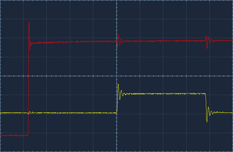
|
|
#
?
Jan 20, 2011 14:46
|
|

|
There's no way to say if that's normal because there doesn't appear to be any scale on anything.
|
|
#
?
Jan 20, 2011 16:17
|
|

|
CapnBry posted:I have this Arduino I'm sending data out to a shift register. The clock pulse is in yellow, and the data is in red, but that's not the question. My question is why the edges of all the pulses look so lovely? All I'm doing is using digitalWrite to toggle the pins on and off. Your edges don't look bad - they all seem to be clean with no glitches. The only problem I can see is that it looks like you have some overshoot/undershoot. As long as you're not exceeding the maximum limits of your parts, I wouldn't worry too much. If you're still curious, read on! This is probably a combination of both crosstalk, transmission line, and probing effects. You can see the crosstalk pretty obviously in second picture - the noise you see on the red trace occurs at the exact same time your edge happens on the yellow trace. Most likely you're either routing your signals very close together, or you have a very poor ground return path, or both. The transmission line effects are not due to the frequency that you're operating at, but rather the frequency of your edge. Now, I don't know how fast arduino drivers are, but if they're in the <1ns range then you really should take transmission lines theory into account. Generally designers will put a series resistor on the driver, to match the driving impedance to the transmission line impedance (this value is usually 30-50 ohms in a 50 ohm system). I'd also throw a 100-200 ohm series resistor on the receiver. This has the added benefit of reducing crosstalk due to reducing edge rate. Last, part of what you're seeing could be due to probing effects of on your scope. Are you using an active probe or a passive probe? Where is your ground point relative to your probe point? Does the scope have any obnoxious DSP to compensate for probe roll off? All of these things can distort the measurement, especially when you're concerned about high frequency content like edges.
|
|
#
?
Jan 20, 2011 16:19
|
|
|
the wizards beard posted:There's no way to say if that's normal because there doesn't appear to be any scale on anything. SnoPuppy posted:If you're still curious, read on!  This is a breadboard representation of another project I've already built that I've been having problems with the LCD getting all messed up. I've tracked its problem down to the lack of a decoupling capacitor on the TTL shift register, but while I was poking around with the oscilloscope, I was wondering if these were normal-looking too. I doubt the signals are too close together, but I can tell you my ground goes from the IC to one of the breadboard busses, to the other end, hops to the other breadboard, goes across that, then jumps a space back into the breadboard, up a pin into a PCB then over to the ground. I've never considered that this might introduce noise. I've always thought "hey everything grounded is grounded!". I'm guessing this isn't the case. I also don't know much about my scope. I've spent probably the past 12 hours of this project just figuring out how to use it and what all the terminology is to find the buttons to press to make it show me what I'm looking for. The scope is an Owon PDS5022S, the cheapest not-used digital scope I could find. I'm sure it isn't top quality, but it has 25MHz bandwidth, 100Msamples/s, and a <14nS rise time whatever that is. I also assume the probes are passive because active sounds more expensive. I can't remember where the ground point was hooked up relative to the probe. Again, I thought ground was ground. Each probe has a ground clip, but I usually just hook up one because... it worked like that. Should each probes clip be attached to a ground near the probe point? I appreciate your detailed response, it is hard to google things without knowing the terminology and just trying to learn about what really happens in circuits.
|
|
#
?
Jan 20, 2011 17:39
|
|
|
longview posted:Any recommendations for something really simple to turn an output on or off from a serial input? You can probably use the DTR line connected through a diode to a voltage divider (or whatever transistor driver you're planning). I don't know much about controlling a serial port with a PC, but there should be a way to toggle it.
|
|
#
?
Jan 20, 2011 20:33
|
|
|
SolidElectronics posted:You can probably use the DTR line connected through a diode to a voltage divider (or whatever transistor driver you're planning). I don't know much about controlling a serial port with a PC, but there should be a way to toggle it. Neat, that line looks perfect for what I need, it looks like DTR control is built into the IO library in .NET! As for the parallel port: I actually had one hooked up for testing but the only way to control it directly from Windows 7 seems to be via third party drivers, otherwise it's limited to data I/O and that didn't work with the 64-bit Windows on my desktop. I'd have done more experimenting but the computer is an old gaming laptop so no serial/parallel (will order a USB adapter).
|
|
#
?
Jan 20, 2011 21:17
|
|
|
CapnBry posted:I've always thought "hey everything grounded is grounded!". I'm guessing this isn't the case. Nope! Whenever a signal is changing, a current is flowing along the wire. Because current only flows in closed loops, the return path for the current is just as important as the actual signal. This return path doesn't have to be through the "ground" - it could easily be through the power connections if that presents the lowest impedance to the signal. The worst case is when the system is designed such that the lowest impedance for the return current is another signal, rather than a ground or power plane. You could try to run a few ground lines in parallel with the signals from the source to the destination - that should reduce your total loop area and provide a cleaner path for your return current. As for the scope, you definitely want to place the ground connection for each probe as close to the signal you're probing as possible. Passive probes will also present a fairly large capacitive load on the signal you're probing - this might not be a big deal, but it can distort edges and cause ringing like you're seeing.
|
|
#
?
Jan 20, 2011 21:21
|
|
|
Hillridge posted:I didn't know the Aoyue irons used the same tips as Hakkos. That'll make it easier to get some variety for mine. I would totally get a bent tip if I were you, they are the best thing ever. mouser's got em
|
|
#
?
Jan 22, 2011 05:11
|
|
|
I was hoping some of the PIC-users here might point me in the right direction. I feel like I'm missing something obvious, probably a Very Important Sentence in the datasheet. I am using a dsPIC30F4012 for a robot project, and trying to get the serial working acceptably. I've got it working, but the divisor has me confused. The mcu is configured to use an external 4MHz crystal with a PLL of 16x, so I would assume I need to use 64MHz in my baudrate calculation, but the baudrate generator value that works suggests I'm running at 16MHz. I can't figure out why. The postscaler is set to 0 (no post scaling) and I can't find anything that would indicate why I'm getting 1/4 of the clock frequency I would expect. Tried a couple different frequencies and got the same results - exactly one forth of the expected value. Is this normal? Am I going crazy?
|
|
#
?
Jan 23, 2011 19:34
|
|
|
Huh. I know the system frequency PIC24s use is half of the clock frequency, so it SHOULD be lower, but I'm not sure why it's 1/4 instead of 1/2. Maybe PIC30s are different, I'd scour the datasheet some more.
|
|
#
?
Jan 23, 2011 20:47
|
|
|
Zo posted:Huh. I know the system frequency PIC24s use is half of the clock frequency, so it SHOULD be lower, but I'm not sure why it's 1/4 instead of 1/2.  yup. I missed a Very Important Formula, apparently. yup. I missed a Very Important Formula, apparently.
|
|
#
?
Jan 23, 2011 21:34
|
|
|
Delta-Wye posted:
This. I cannot begin to count the hours I've wasted jumping from family to family of PIC, and forgetting the particular relationships between Fosc, Fcy and others. For added fun, if you configure OSCO to output the clock signal, you have to find the one sentence in the datasheet where it lets you know that the frequency at the pin is 1/4 of actual FCY (PIC18). In my defense, it was 6AM and 12 hours of coding in, but still frustrating 
|
|
#
?
Jan 24, 2011 22:30
|
|

|
I've learned to embrace the way of the PIC because no matter how frustrating all that poo poo is, stuff like PPS will save your rear end so hard one day you'll praise microchip like a god. Also, at least it's documented SOMEWHERE (freescale )
|
|
#
?
Jan 24, 2011 22:37
|
|
|
movax posted:This. I cannot begin to count the hours I've wasted jumping from family to family of PIC, and forgetting the particular relationships between Fosc, Fcy and others. For added fun, if you configure OSCO to output the clock signal, you have to find the one sentence in the datasheet where it lets you know that the frequency at the pin is 1/4 of actual FCY (PIC18). In my defense, it was 6AM and 12 hours of coding in, but still frustrating On the PIC18s at least, the instruction clock is 1/4 the oscillator frequency because it takes 4 cycles per instruction. I'm surprised to see FOSC/4 on the dsPICs though, because I thought they have 2-cycle instruction execution.
|
|
#
?
Jan 24, 2011 22:53
|
|
|
Any good tutorials on Cadence PCB designer? Eagle was cake but it seems like Cadence is a bitch to even figure out the GUI.
seo fucked around with this message at 03:54 on Jan 25, 2011 |
|
#
?
Jan 25, 2011 03:48
|
|
|

|
| # ? May 13, 2024 03:18 |
|
|
CapnBry posted:From the screenshots you posted it looks like when signal A changes state there is ringing on signal B and vice-versa. That makes it sound like you are switching large currents, and since you seem to be doing a reasonable job of trying to decouple stuff close to the chips the next place to look is at the load you are switching into. What is the input impedance of your probes? If they are terminated with 50 Ohms you would be drawing so much current out of each output that your decoupling caps can't keep up. A simple test would be to unclip your oscilloscope probe, clip it onto one side of a 10k resistor and plug the other end into the signal you want to look at. If the cross-coupling effect goes away the probe impedance is too low. Some scopes have a high/low input impedance setting that you can switch to fix the problem in a more permanent way.
|
|
#
?
Jan 25, 2011 03:58
|
|
