


|
Here's what I've been working on and pulling my hair out about lately. I made an edge detection/subsampler type device. It's a DAC and a comparator that feeds into an FPGA with a delay line time to digital converter programmed into it. I'll be using it to calculate the time of flight of my UWB transmitter/receiver. A 20 ns pulse on my USB scope (50 ns/div): http://www.empiresmod.com/krenzo/usb_scope.png A 20 ns pulse on my edge detection subsampler (500 ps/div): http://www.empiresmod.com/krenzo/edge_detection.png That's with 4 samples averaged together per point. It's jittery because the clock generator on the Spartan 3E has over 100 ps jitter, and the DAC contributes to the noise a little. I hope it improves when I migrate to a Spartan 6 later. Krenzo fucked around with this message at 09:32 on Aug 29, 2011 |
 #
?
Aug 29, 2011 09:29
#
?
Aug 29, 2011 09:29
|
|


|

|
| # ? May 8, 2024 20:18 |
|
|
I finally figured out my FPGA issue. It was, as I suspected, something dumb I did. After conf_done goes high to signal that the device received its programming, the FPGA requires 2 more clock pulses before it initializes. By controlling my buffers with conf_done, I was shutting off the clock line before these last 2 pulses went in. The slight amount of capacitance delayed the buffer shut off just long enough to make it work. Unparagoned posted:I want to move into SMD PCBs and was wondering how important is soldermask. Would it be possible to solder SMD stuff as a novice on a naked board without solder mask? I build SMD PCBs all the time and I've never used a soldermask. If you designed a product and plan to run big batches of them it might be worth it, but not for prototypes.
|
|
#
?
Aug 29, 2011 16:33
|
|

|
I've got a Rigol DS1052E, and I'm thinking about upgrading. Mainly I'd be looking for a bigger screen (higher res) and 4 channels. Bandwidth isn't important - 50MHz is enough. Are there any good alternatives below 1000bux?
|
|
#
?
Aug 30, 2011 15:55
|
|

|
Get a used/refurbished one on eBay. I don't think I've ever seen a new 4-channel DSO for under $1000.
|
|
#
?
Aug 30, 2011 18:22
|
|
|
 IMG_20110824_090812.jpg by nerobro, on Flickr Hey, look, it actually works. That's the output waveform from that inverter, with a very light AC load on it. That's ugly as hell, but it proves the DSO actually works.
|
|
#
?
Aug 30, 2011 19:07
|
|

|
Nerobro posted:
Huh. I'd be curious to know how flat the frequency response is from DC to the analog bandwidth, as well as any weird amplitude-related-nonlinearities. But that would require a decent signal generator and patience, lol.
|
|
#
?
Aug 30, 2011 20:18
|
|
|
I've got this pretty basic circuit which 3 data lines and an "enable" line from 2 pins of a microcontroller using a shift register. The 3 bits of data are shifted in to the register with the high bit set (MSB) 1 C B A 0 0 0 0 (LSB). Once the data is shifted in, I raise the UC_DATA line again and the simple diode-logic AND gate should AND that high bit with the data line and put out a digital 1 on the OUTPUT line: Then I lower UC_DATA and shift in all 0s to clear it. This works fine in 80% of the devices I've built with this. However the 5th wasn't working so touched OUTPUT with the oscilloscope probe and it worked like a charm. Take the probe away and it stops working. Tried it with a multimeter too, when measuring OUTPUT it works but as soon as you stop measuring it it stops working. I had found the Heisenberg Circuit. After checking each connection 5 to 10 times and determining everything was hooked up right it left me scratching my head. I then put a 2.2K resistor to ground on the output line and it worked without me measuring it, although the voltage of OUTPUT was obviously only 3.4V (2.2k/3.2k voltage divider). Finally, I replaced the switching diode, a 1N4148 with a 1N4001 and it worked perfectly. I guess my question is, what property of the 1N4001 diode allowed it to work? Here's what I see on the oscilloscope for the two different diodes (both work when attached to the scope). The red is OUTPUT and the yellow is UC_CLK. You can see the 1s shifting in to place not triggering the AND gate and finally the enable pulse on OUTPUT. 1N4148  1N4001 
|
|
#
?
Aug 30, 2011 20:34
|
|

|
Without any critical thought about it, I'm gonna put my money on capacitance. It's loving always capacitance. Now, someone smart explain why
|
|
#
?
Aug 30, 2011 20:43
|
|
|
Astrolite posted:I've got a Rigol DS1052E, and I'm thinking about upgrading. Mainly I'd be looking for a bigger screen (higher res) and 4 channels. Bandwidth isn't important - 50MHz is enough. Are there any good alternatives below 1000bux? This got me thinking. Does anyone make a scope that has DVI or HDMI (or even VGA) and uses a standard LCD for display? It'd be pretty rad to have a 23" scope.
|
|
#
?
Aug 30, 2011 21:11
|
|


|
taqueso posted:This got me thinking. Does anyone make a scope that has DVI or HDMI (or even VGA) and uses a standard LCD for display? It'd be pretty rad to have a 23" scope. Well I think most modern digital scopes are essentially just a computer with extra hardware to do the sampling, and therefore, they have video out. It looks like Tektronix's DPO scopes all have video out, VGA on the low end and DVI on the high end. I think it would be much cheaper to get a laptop and a USB scope though. A lot of scopes also have USB output. I don't know what all that can be used for, but it's probably to export your waveform to a computer where you can then view it on a larger screen. Krenzo fucked around with this message at 22:08 on Aug 30, 2011 |
|
#
?
Aug 30, 2011 22:04
|
|
|
I'm having trouble working out if I can use a MOSTFET driver, or if they will work for my situation. The situation is that I need to have an output that is on when it's on but when it's off it's completely isolated. What I have done so far is use a PNP mosfet on the high side and a npn mosfet on the low side. I've used a couple of other mosfets to drive it from a PIC 3.3V signal. I've kind of found out about mosfet drivers and had a look at half bridge drivers and it seems like the kind of thing I want/should use. Some of them are based on having a npn on the high side as well but I don't really want to do that. I've brought about quite a few but none seem to do what I want. I'm not really sure what exactly I should be looking for. Here is the current circuit, I was kind of hoping I could replace R12-R14 and T8 & T9 with a mosfet driver. Any advice?
|
|
#
?
Aug 30, 2011 22:08
|
|
|
Nerobro posted:
|
|
#
?
Aug 31, 2011 06:09
|
|
|
Astrolite posted:I've got a Rigol DS1052E, and I'm thinking about upgrading. Mainly I'd be looking for a bigger screen (higher res) and 4 channels. Bandwidth isn't important - 50MHz is enough. Are there any good alternatives below 1000bux? If you find something good, even if its only something you found used, let the thread know! I was thinking about buying a new digital scope, since the one I currently have is ANCIENT (like, a huge green CRT that's a couple feet deep, with part of interface burned into it). I still like my old Tektronix analog scope, but it's an old, finicky whore--too many switches are iffy, and the calibration is off on one channel). I would repair it, since I found the huge service manual at one point, but it's really complicated and I don't want it to break. I was gonna get the Rigol scope, if only because two channels is generally enough (esp. since I got a dedicated logic analyzer for looking at big digital interfaces). Was there anything wrong with the Rigol besides the 2-channels, and the screen size? Unparagoned posted:I'm having trouble working out if I can use a MOSTFET driver, or if they will work for my situation. The situation is that I need to have an output that is on when it's on but when it's off it's completely isolated. What I have done so far is use a PNP mosfet on the high side and a npn mosfet on the low side. I've used a couple of other mosfets to drive it from a PIC 3.3V signal. I've kind of found out about mosfet drivers and had a look at half bridge drivers and it seems like the kind of thing I want/should use. Some of them are based on having a npn on the high side as well but I don't really want to do that. I've brought about quite a few but none seem to do what I want. I'm not really sure what exactly I should be looking for. Here is the current circuit, I was kind of hoping I could replace R12-R14 and T8 & T9 with a mosfet driver. Any advice? I'm not sure what you're saying for most of this, so let me ask: what kind of load is it (resistive? resistive + inductive?) and what do you mean by "completely isolated" when its off?
|
|
#
?
Aug 31, 2011 16:18
|
|
|
Unparagoned posted:I'm having trouble working out if I can use a MOSTFET driver, or if they will work for my situation. The situation is that I need to have an output that is on when it's on but when it's off it's completely isolated. What I have done so far is use a PNP mosfet on the high side and a npn mosfet on the low side. I've used a couple of other mosfets to drive it from a PIC 3.3V signal. I've kind of found out about mosfet drivers and had a look at half bridge drivers and it seems like the kind of thing I want/should use. Some of them are based on having a npn on the high side as well but I don't really want to do that. I've brought about quite a few but none seem to do what I want. I'm not really sure what exactly I should be looking for. Here is the current circuit, I was kind of hoping I could replace R12-R14 and T8 & T9 with a mosfet driver. Any advice? First, you have bipolar transistors in your schematic, not MOSFETs. I also assume that when you say "when it's off it's completely isolated" means that you want to tristate the output in the off condition, and have both FETs conducting when in the "on" state. Second, PMOS FETs tend to have much higher on resistance than NMOS FETs. This leads to increased power wasted as heat. I would personally try to use NMOS for both transistors, since it would be more efficient and would reduce the number of unique components in the design. The other problem you will have is with the Vgs of the PMOS FET if you're trying to drive it with 100 volts. You can use the resistor divider that you have (although you might want to increase the value of R12), but a safer way would be to use a zener in parallel with a resistor. If you decide to use NMOS for both transistors, I would definitely suggest using a FET driver circuit so that you can use N-FETs for both the top and bottom transistors. From about 2 min of looking, IRF has a part that does exactly what you want: http://www.irf.com/product-info/datasheets/data/ir2213.pdf It has independent controls for the high and low side drivers, so you can completely tristate the output if you want. If you're dead set on using a combination of PMOS/NMOS, what you have now if probably as good a design as any. It will certainly be cheaper than a FET driver IC.
|
|
#
?
Aug 31, 2011 17:04
|
|
|
What's the hobbyist PCB fab of choice these days? I'm primarily interested in low cost options. It's 2 sided, and I don't need any frills, but would appreciate a reasonable turn around time.
|
|
#
?
Aug 31, 2011 21:09
|
|
|
Slanderer posted:I'm not sure what you're saying for most of this, so let me ask: what kind of load is it (resistive? resistive + inductive?) and what do you mean by "completely isolated" when its off? SnoPuppy posted:First, you have bipolar transistors in your schematic, not MOSFETs. I also assume that when you say "when it's off it's completely isolated" means that you want to tristate the output in the off condition, and have both FETs conducting when in the "on" state. I'm just in the habit of using the same symbols for for all transistors sorry. They should be MOSFET symbols. Thanks for explaining that PMOS have higher on resistance which means energy is wasted. The reason I was set on not having to NMOS was that there was too much of a drop over the top NMOS when I tried it. I looked up the datasheets and the NMOS I was trying it with had an on resistence of 5ohm which is very high. I've never actually looked at the on resistence before so thanks for bringing it up. I think I have like every IR driver apart from that one, I have the 2003,2113,2117,2304. I'll play with them some more but haven't got any of them to work that well yet unless the device is suppose to be some kind of explosive. Any way the really important thing I learned today is with IC if you: Wire them up slightly wrong they get warm, Wire them up really badly they burn up, If you really gently caress up they explode :/ FSMC fucked around with this message at 21:16 on Aug 31, 2011 |
|
#
?
Aug 31, 2011 21:11
|
|
|
Hillridge posted:What's the hobbyist PCB fab of choice these days? I'm primarily interested in low cost options. It's 2 sided, and I don't need any frills, but would appreciate a reasonable turn around time. If you are in the UK then http://www.spiritcircuits.com/services/go-naked is very fast and free.
|
|
#
?
Aug 31, 2011 21:17
|
|
|
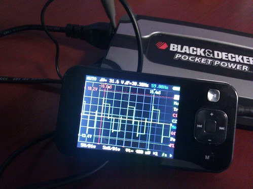
Pizer posted:What are you using to display the waveform? Looks handy. Clipped the ground lead to one side of the AC socket, and the sense lead to the other. And set the probe to 10x. No real magic there. The load was a battery charger.
|
|
#
?
Aug 31, 2011 21:40
|
|
|
Hillridge posted:What's the hobbyist PCB fab of choice these days? I'm primarily interested in low cost options. It's 2 sided, and I don't need any frills, but would appreciate a reasonable turn around time. advanced circuits is pretty good about getting quick stuff out. their main thing is "33 each", wherein you get standard spec boards for that price. Not sure if they still make you get at least 3, but I've definitely heard that you can get single quantities. If you want it even faster, they'll do bare bones @ like 1 day turn around. No solder mask, no silk screen, and a bunch of other caveats, but it's quick and pretty cheap. 33 each is really the way to go, though. Soldermask, at least for SMT work, is really helpful for a whole bunch of reasons.
|
|
#
?
Aug 31, 2011 22:04
|
|
|
Unparagoned posted:Completely isolated is just like SnoPuppy assumes, tristate(had to wiki that). The load is the human body, so resistance and capacitance. All the outputs are connected through the body which is why I need a tristate when the output should be off. Alright, this is going to require some explanation, especially since your circuit says 100 V. I had to follow a whole bunch of restrictions wrt/ maximum current vs. frequency when I was driving 5V into the body in my EKG designs. I don't know what you want this circuit to do, but don't. Because it's probably six different kinds of retarded.
|
|
#
?
Aug 31, 2011 22:09
|
|
|
As a hobbyist who has build 100Vdc power supplies, I wouldn't let a hobbyist's 100Vdc anywhere near me. That poo poo loving hurts.
|
|
#
?
Aug 31, 2011 22:24
|
|
|
Slanderer posted:Not sure if they still make you get at least 3, but I've definitely heard that you can get single quantities. In my experience it it usually not really much cheaper to get less than 3 (sometimes as many as 10) boards, since the price per board will go up enough to make the total about the same. I've been happy with MyRO for my last few prototypes, but these boards are multilayer and have smaller holes & tighter trace/space than most proto specials allow. PCBFabExpress can be pretty competitive on protos. BatchPCB charges by the square inch IIRC and might be good for a small board or if you really only want 1 board. I've never used them, though. Also, there is that fab house that eevblog went off on for changing the shape of his fill and breaking continuity. But I remember them being insanely cheap. I guess there is a wiki somewhere with instructions on how to accommodate this place since they will gently caress with your gerbers. e: That naked deal from above is pretty drat amazing.. VVV And itead is the place that I was thinking of from eevblog. Here is that page about using them: https://github.com/dren-dk/HAL900/wiki/Quirks-of-PCB-manufacturing-at-ITead taqueso fucked around with this message at 22:52 on Aug 31, 2011 |
|
#
?
Aug 31, 2011 22:34
|
|
|
Hillridge posted:What's the hobbyist PCB fab of choice these days? I'm primarily interested in low cost options. It's 2 sided, and I don't need any frills, but would appreciate a reasonable turn around time. There's a couple of chinese companies that resell services from some chinese fab. http://iteadstudio.com/store/index.php?main_page=index&cPath=19_20 http://www.seeedstudio.com/depot/fusion-pcb-service-p-835.html?cPath=185 I've used iteadstudio before and it worked out pretty well. You can get 10, 5cm x 5cm double sided boards with silk and soldermask for $10. I think it took 2 weeks from when I sent gerbers to when I had boards in hand, and I used the cheapest shipping option they had. They won't be able to hold your hand, and if you have any DRC errors they probably won't let you know (your boards might not work). I'd also be conservative on the trace and space they claim - I wouldn't go below 8/8 and a 25 mil via, and I'd go much bigger if possible. edit: taqueso posted:Also, there is that fab house that eevblog went off on for changing the shape of his fill and breaking continuity. But I remember them being insanely cheap. I guess there is a wiki somewhere with instructions on how to accommodate this place since they will gently caress with your gerbers. These are the places I mentioned. I think the guy on the eevblog actually violated the DRC rules slightly, so they changed the gerbers to make them "conform." As long as you're conservative with your design rules, it should be ok. Besides, you're only paying $10. SnoPuppy fucked around with this message at 23:03 on Aug 31, 2011 |
|
#
?
Aug 31, 2011 22:44
|
|
|
Slanderer posted:Alright, this is going to require some explanation, especially since your circuit says 100 V. I had to follow a whole bunch of restrictions wrt/ maximum current vs. frequency when I was driving 5V into the body in my EKG designs. It's a TENS machine. That voltage is fairly standard for tens machines. I have a working circuit, it's just I wanted to see if I could improve it.
|
|
#
?
Aug 31, 2011 23:09
|
|
|
Slanderer posted:Alright, this is going to require some explanation, especially since your circuit says 100 V. I had to follow a whole bunch of restrictions wrt/ maximum current vs. frequency when I was driving 5V into the body in my EKG designs. I'm with this guy. If you're retarded enough to explode ICs, you should not be attaching your projects to human beings. Please give up.
|
|
#
?
Aug 31, 2011 23:11
|
|

|
Corla Plankun posted:I'm with this guy. If you're retarded enough to explode ICs, you should not be attaching your projects to human beings. Please give up. I dunno about that, having an IC explode is something that will happen (rarely) to pretty much everyone from time to time and doesn't make you retarded. We all make mistakes, etc. But if you just learned that it can happen, you are way too inexperienced to be designing a TENS system. Things like using the wrong symbol for your mosfets and using the wrong terms for almost everything also reveals a lack of experience. taqueso fucked around with this message at 23:28 on Aug 31, 2011 |
|
#
?
Aug 31, 2011 23:23
|
|
|
Slanderer posted:advanced circuits is pretty good about getting quick stuff out. their main thing is "33 each", wherein you get standard spec boards for that price. Not sure if they still make you get at least 3, but I've definitely heard that you can get single quantities. You can get single quantities if you are a college student. Basically that means you tell them you're a student and you have to have it shipped to an address on a college campus. taqueso posted:In my experience it it usually not really much cheaper to get less than 3 (sometimes as many as 10) boards, since the price per board will go up enough to make the total about the same.
|
|
#
?
Sep 1, 2011 02:23
|
|


|
SnoPuppy posted:There's a couple of chinese companies that resell services from some chinese fab. I have used seeed studio before with great results. These boards look as good as anything from BatchPCB or Advanced circuits, if you stay strictly inside their DRC rules. At $10 for 10 boards, it's a no brainer. I usually have more than one project kicking around anyway, so a 2 week wait isn't a big deal.
|
|
#
?
Sep 1, 2011 12:49
|
|
|
Slanderer posted:I was gonna get the Rigol scope, if only because two channels is generally enough (esp. since I got a dedicated logic analyzer for looking at big digital interfaces). Was there anything wrong with the Rigol besides the 2-channels, and the screen size? I'm a mechanical engineer, so I don't have in-depth knowledge of oscilloscopes, but the Rigol is in my experience a pretty drat good option for a budget hobbyist. As for other weaknesses, nothing serious really. The cursor interface is a tad kludgy, and takes up a lot of screen space. It's got a fan which is kind of noisy. The refresh rate when looking at low-frequency signals is rather poor, but I don't know how other scopes would compare. Apart from that, I'm very happy with it. I also agree that 2 channels is enough most of the time. It was kinda inconvenient however when debugging my multi-stage coilgun. 4 channels would have been great for monitoring two full stages (optodetector and coil) simultaneously.
|
|
#
?
Sep 1, 2011 13:59
|
|
|
http://dorkbotpdx.org/wiki/pcb_order has been my place of choice. It's usually a pretty quick turnaround once an order closes and ships, price can't be beat, and I have had no trouble with the quality. I think he just panelizes hobbyists' boards and sends them to gold phoenix but it gets you a price you can't get without ordering a shitload of boards. Shipping is included, and the guy is easy to work with. If you do order though, tell him to knock off the purple though. I'm tired of purple boards  I guess he just gives them RGB values and they mix it custom for the order. I want to get some white soldermask with black silkscreen, that combo looks hot. I guess he just gives them RGB values and they mix it custom for the order. I want to get some white soldermask with black silkscreen, that combo looks hot.
|
|
#
?
Sep 1, 2011 18:56
|
|

|
I hope I don't make you sad, Delta-Wye... Are there any starving EE students (or anyone, really) out there who would like to make a few extra bucks on the side? We'll discuss details/rates/etc. off-thread, but if you're interested, PM me or shoot me an email at gshort2@gmail.com (that address works for google talk as well, and I'm always on) and we can talk details. None of the projects are really major, at least they sure as hell shouldn't be, by design. Depending on which project you want to work on, you may be doing some basic circuit design, or finalizing said designs, and almost certainly some PCB layout. The end result will be you giving me the files the PCB manufacturer needs, and then me bitching because when I solder it up it doesn't work, and then you showing me that I put all my caps in backwards. Really it's just a few hobby projects that I may never get around to finishing because I have this problem with the last 10% of any project. I won't be paying professional contractor rates, because I'm not THAT rich and this isn't professional contractor level work. This'll be more like...mowing the lawn, with a commensurate pay rate. But hey, if it means you can go to Red Lobster again this week, why not? tl;dr:  I WANT TO GIVE YOU MY MONEY I WANT TO GIVE YOU MY MONEY Once again: PM, or email/google talk gshort2@gmail.com (If this is considered bad form this posting here, my apologies, I'll remove it, but I figured nobody would complain if I offered some poor goon some extra cash.)
|
|
#
?
Sep 1, 2011 21:14
|
|


|
Delta-Wye posted:http://dorkbotpdx.org/wiki/pcb_order has been my place of choice. It's usually a pretty quick turnaround once an order closes and ships, price can't be beat, and I have had no trouble with the quality. I think he just panelizes hobbyists' boards and sends them to gold phoenix but it gets you a price you can't get without ordering a shitload of boards. Shipping is included, and the guy is easy to work with. Unless he's got a special arrangement with Gold Phoenix, they charge something like $20 *per design* if you panelize it yourself. At least, that's what they charged me, and I think that's why they charged it.
|
|
#
?
Sep 1, 2011 21:20
|
|
|
Delta-Wye posted:http://dorkbotpdx.org/wiki/pcb_order has been my place of choice. Does iteadstudio.com route custom shapes or do they have to be rectangular?
|
|
#
?
Sep 2, 2011 17:14
|
|
|
CapnBry posted:I've only used DorkbotPDX, but have had good experience with the two designs I've sent them. I thought "I just can't beat $24 shipped for 3x 2.0"x2.4" boards" but now I see that there are better deals direct from China. I sent him a design at 4pm the day before they closed a panel and I had boards in my hand 10 days later. I'm no professional but they looked good and worked despite being purple. I'm pretty sure all designs must be rectangular. Doing individual route borders would be too expensive.
|
|
#
?
Sep 2, 2011 20:20
|
|
|
My days of being an intern are at an end. I just finished (well, am finishing) my first week as an actual engineer. I'm not designing circuits, but instead I'll be writing embedded code and debugging/analyzing hardware. I'm basically the property of one of the senior engineers here, but on the plus side I'll be getting the chance to finally improve my embedded coding. RTOS's and all that crap, too. Also: no soldering iron burns is a total plus.
|
|
#
?
Sep 2, 2011 20:25
|
|
|
Okay, quick question. I'm just barely learning about electronics, and I'm currently learning about RC circuits. I know how to calculate the seconds it takes to charge a capacitor to 63%, and I feel silly for even asking instead of just finding out myself, but I won't have the money to buy the stuff I need for another week, and I can't find it online. My question is, if I set up circuit with a battery, a resistor, a capacitor with values to make a 10 second timing oscillator, and an LED, when will the LED light up? When the capacitor hits 63%? Or before?
|
|
#
?
Sep 3, 2011 04:50
|
|

|
Bon Mot posted:Okay, quick question. I'm just barely learning about electronics, and I'm currently learning about RC circuits. I know how to calculate the seconds it takes to charge a capacitor to 63%, and I feel silly for even asking instead of just finding out myself, but I won't have the money to buy the stuff I need for another week, and I can't find it online. My question is, if I set up circuit with a battery, a resistor, a capacitor with values to make a 10 second timing oscillator, and an LED, when will the LED light up? When the capacitor hits 63%? Or before? Do you have a schematic in mind, or can link to? It depends on a lot of things. EDIT: 63% of what? How is everything hooked up? etc etc
|
|
#
?
Sep 3, 2011 04:55
|
|
|
I guess I wasn't very clear. What I'm trying to ask is if I make a circuit with a 9v battery, 10 kO resistor, a 1000 uF capacitor, and an LED to make a 10 second RC timer, after 10 seconds will it suddenly complete the circuit and light up the LED, or will the LED slowly light up as the capacitor charges? edit: And if it does slowly light up as the capacitor charges, how would I be able to make a timer circuit that switches an LED on after 10 seconds without using a 555 timer? The idea is to wire up 3 LED's that turn on a couple seconds apart after flipping a switch. Bon Mot fucked around with this message at 05:47 on Sep 3, 2011 |
|
#
?
Sep 3, 2011 05:44
|
|
|
Bon Mot posted:I guess I wasn't very clear. What I'm trying to ask is if I make a circuit with a 9v battery, 10 kO resistor, a 1000 uF capacitor, and an LED to make a 10 second RC timer, after 10 seconds will it suddenly complete the circuit and light up the LED, or will the LED slowly light up as the capacitor charges? I'm not too sure what exactly you want. This has the capacitor charging up, when it reaches the threshold voltage of the mosfet it then turns it on and then the LED lights up. LED stays lighted up. The the capacitor would need to charge up to the threshold voltage of the mosfet, you need to use this voltage when working out the time. I tried to make the circuit as simple as possible. Edit: Circuit in post below FSMC fucked around with this message at 15:15 on Sep 3, 2011 |
|
#
?
Sep 3, 2011 15:13
|
|
|

|
| # ? May 8, 2024 20:18 |
|
|
The circuit
|
|
#
?
Sep 3, 2011 15:14
|
|